The following section details the MDIS generic properties for the MDISBaseObjectType. Implementations shall ensure adherence to Mandatory [M] aspects in order to comply with the MDIS interface standardisation. Optional [O] may or may not be implemented within a project. Figure 9 provides an overview of the MDISBaseObjectType as defined by MDIS. This Object is intended to be the base object for all other MDIS ObjectTypes (see Figure 10 for an overview of inherited types)
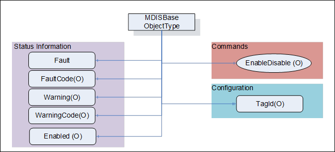
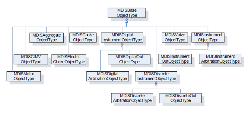
Figure 10 – Base Object Hierarchy
The Table 4 defines the structure of an MDISBaseObjectType.
Table 4 – MDISBaseObjectType Definition
|
Attribute |
Value |
||||
|
BrowseName |
MDISBaseObjectType |
||||
|
IsAbstract |
True |
||||
|
References |
Node Class |
BrowseName |
Data Type |
TypeDefinition |
Other |
|
Subtype of the 0:BaseObjectType defined in OPC 10000-5 |
|
||||
|
0:HasComponent |
Variable |
Fault |
0:Boolean |
0:BaseDataVariableType |
M, RO |
|
0:HasComponent |
Variable |
Warning |
0:Boolean |
0:BaseDataVariableType |
O, RO |
|
0:HasComponent |
Variable |
Enabled |
0:Boolean |
0:BaseDataVariableType |
O, RO |
|
0:HasProperty |
Variable |
TagId |
0:String |
0:PropertyType |
O, RO |
|
0:HasComponent |
Method |
EnableDisable |
See 6.2.3 |
O |
|
|
0:HasComponent |
Variable |
FaultCode |
0:UInt32 |
0:BaseDataVariableType |
O, RO |
|
0:HasComponent |
Variable |
WarningCode |
0:UInt32 |
0:BaseDataVariableType |
O, RO |
|
|
|
|
|
|
|
|
0:HasSubtype |
ObjectType |
MDISDigitalInstrumentObjectType |
|
||
|
0:HasSubtype |
ObjectType |
MDISDiscreteInstrumentObjectType |
|
||
|
0:HasSubtype |
ObjectType |
MDISChokeObjectType |
|
||
|
0:HasSubtype |
ObjectType |
MDISElectricChokeObjectType |
|
||
|
0:HasSubtype |
ObjectType |
MDISInstrumentObjectType |
|
||
|
0:HasSubtype |
ObjectType |
MDISValveObjectType |
|
||
|
0:HasSubtype |
ObjectType |
MDISCIMVObjectType |
|
||
|
0:HasSubtype |
ObjectType |
MDISMotorObjectType |
|
||
|
0:HasSubtype |
ObjectType |
MDISAggregateObjectType |
|
||
|
ConformanceUnits |
|||||
|
MDIS Base Fault |
|||||
The RW column indicates if a Node of Variable NodeClass is readable, writeable or both readable and writeable. Other NodeClasses (Object, Method) do not support reading or writing and do not fill in this column.
By definition a Profile can require that an Optional item be provided, it cannot change the behaviour of an Object from what is described in this specification, which includes support for any Mandatory items. Profiles are described in section 14.3.
Fault – The status of the object, true if any fault exists.
Warning – The status of the object, true if any warnings exist. A warning does not require immediate operator action.
Enabled – This Variable is set as enabled (true) by default. When disabled the Object will not report any dynamic information other than a bad status code (Bad_InvalidState). It will still report configuration related information. It will disable execution of any method that might be defined as part of the Object. For the MDISBaseObjectType the default is that only the Enabled flag, TagId and EnableDisable Method report values or perform functions. Subtypes of this ObjectType may describe additional requirements for disabled Objects.
TagId – The TagId is a unique equipment identifier. This is additional information that can be used to help identify the Variable associated with the instance of this type. This field is intended to be used to store the tag id from the P&ID.
EnableDisable – This Method allows a Client to disable or enable the Object.
FaultCode – An unsigned integer that describes a fault code(s), zero indicates no fault. The FaultCode is a 32 bit mask, with 16 bits for standard defined codes and 16 bits for vendor defined codes. Each of the Subtypes of this ObjectType defined in this specification shall define a set standard FaultCodes that apply to that ObjectType (bits 0-15). In addition, the SPCS vendor may provide vendor specific bits (bits 16-31). Once a Bit is defined (given a name), then in all Objects that use that same named fault, the same bit number is used.
WarningCode – An unsigned integer that describes a warning code(s), zero indicates no warning. The SPCS vendor will provide a definition of what the number means The WarningCode is a 32 bit mask, with 16 bits for standard defined codes and 16 bits for vendor defined codes. Each of the subtypes of this ObjectType defined in this specification shall define a set standard WarningCodes that apply to that ObjectType (bits 0-15). In addition, the SPCS vendor may provide vendor specific bits (bits 16-31). Once a Bit is defined (given a name), then in all Objects that use that same named warning, the same bit number is used.
EnableDisable is used to disable or enable an Object. The enable / disable operation applies to the Object in the UA Server. The call completes when the enable / disable operation is complete. The Server may or may not pass the enable / disable down to lower levels. This is Server specific behaviour.
Signature
EnableDisable (
[in] 0:Boolean Enable );
Table 5 – EnableDisable Method parameters
|
Argument |
Description |
|
Enable |
Boolean indicator of whether the Object is to be disabled or enabled. A true indicates that the Object is enabled. |
Method result codes are defined as part of the Call Service (see OPC 10000-4). They are described in Table 124 for ease of reference.
Comments
The EnableDisable Method will disable or enable this Object. Once the state of an Object is changed by this Method (i.e., disabled) the state will be maintained until this Method is called again to change the state (i.e., enable). The Method will report if any error occurs while disabling or enabling the Object. Table 6 specifies the AddressSpace representation for the EnableDisable Method.
Table 6 – EnableDisable Method AddressSpace Definition
|
Attribute |
Value |
||||
|
BrowseName |
EnableDisable |
||||
|
References |
Node Class |
BrowseName |
DataType |
TypeDefinition |
Other |
|
0:HasProperty |
Variable |
0:InputArguments |
0:Argument[] |
0:PropertyType |
M |
|
ConformanceUnits |
|||||
|
MDIS Base Enabled |
|||||