
4 General information on LADS and OPC UA
4.1 Introduction to LADS
4.1.1 Overview
LADS, an acronym for Laboratory and Analytical Device Standard, is a manufacturer-independent, open standard for analytical and laboratory equipment. It comprehensively encapsulates various customer industries and their respective workflows, providing a sustainable application that also caters to the future demands of digitalization and automation. LADS is built upon OPC UA, an open communication platform developed and promoted by the international non-profit OPC Foundation. OPC UA facilitates cross-vendor communication and interoperability in industrial automation processes.
The benefits of the LADS standard are listed below:
Manufacturer-independent standard
Open standard, capable of integrating instruments in different workflows
Plug and play interoperability of Lab and Analytical Devices
Covers a wide range of different Lab and Analytical devices through device-type-agnostic design principles
Future versions may allow machine-readable semantic contextualization of LADS patterns by linking nodes within the information model to suitable taxonomies and ontologies (utilizing Dictionary References OPC 10000-19)
4.1.2 Introduction to the structure of a LADS Device
The Laboratory and Analytical Device Standard (LADS) Companion Specification provides a comprehensive framework for modelling and managing analytical and laboratory equipment. It does this by defining two primary views: the Hardware View and the Functional View.
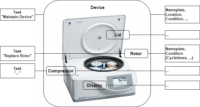
4.1.2.1 Hardware View - Devices & Components
The Hardware View focuses on the physical aspects of the devices and their components. This view is essential for various use cases related to asset management, including enhanced serviceability.
Key features of the Hardware View are introduced in the following subsections.
4.1.2.1.1 Devices
These are modelled with properties such as nameplates, installation dates, condition monitoring, and calibration & validation status.
4.1.2.1.2 Components
Hardware components like the Lid, Rotor, Drive, and Compressor are modelled in a sub-tree. Each component exposes its individual nameplate and maintenance-related information, similar to the device itself, and can also have components itself.
4.1.2.1.3 Tasks
Recurrent tasks that affect either the entire device or individual components (such as inspection, maintenance, calibration, validation, cleaning, etc.) can be organized via LADS.
4.1.2.1.4 Example of a Hardware View of a centrifuge
Figure 1 shows a centrifuge, including various components and the corresponding component data.
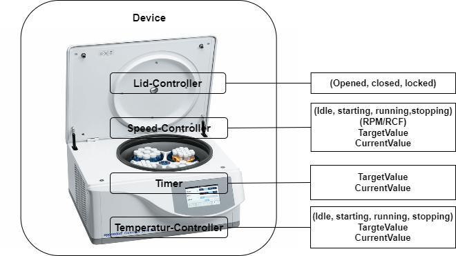
4.1.2.2 Functional View
The Functional View deals with data relevant for the operation, automation, and orchestration of an instrument.
Key aspects of the Functional View are introduced in the following subsections.
4.1.2.2.1 Functions
Actions to achieve a specific outcome. (Typical functions include but are not limited to sensors, controllers, actuators, timers, etc. They may utilize one or more tangible components.)
The complete list of Functions can be found in section 7.4
Figure 2 shows a centrifuge, including various components and the corresponding component data.
4.1.2.2.2 Programs
Many laboratory and analytical devices allow the user to define and run programs, also called methods. The Program Manager organizes program templates, runs programs, and manages the result data generated during a run, providing device-level orchestration.
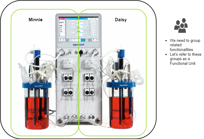
4.1.2.2.3 Functional Units
Functional Units are aggregations of functions designed to achieve a specific outcome. Typically, a Functional Unit is utilized by only one user at a time and exposes its current state. It may optionally include a Program Manager. A Functional Unit can be seen as a virtual device within a LADS Device, grouping together several (potentially redundant) functions. This concept is particularly useful when a LADS Device contains multiple functions that can be grouped as virtual devices or behave as separate devices. In such cases, a LADS Device can be divided into multiple Functional Units, with each Functional Unit representing a virtual device.
For instance, consider a bioreactor vessel with two separate interfaces (see Figure 3). Each container has its own functions, such as a temperature sensor and a motor, and its own program. This setup allows the bioreactor to be split into two Functional Units, each representing a separate container with its own program and set of functions.
4.1.3 Introduction to the state machines and Device status variables used
4.1.3.1 Overview
This section provides an overview of the state machines and device status variables used in the LADS Companion Specification. It explains the relationship between various state machines and status variables in the context of a LADS Device, its Components, and Functional Units.
The relationship between these state machines and status variables is crucial for understanding the operation and management of a LADS Device. The state of the LADS Device state machine and the FunctionalUnit state machines come first and form the basis for the MachineryItemState. The MachineryOperationMode provides additional context about the type of Tasks being performed. The DeviceHealth and DeviceHealthAlarms provide information about the device's condition and any Alarms that may have been triggered.
Refer to Annex B for proposed mappings between the DeviceStateMachine, the FunctionalUnit state machines, the MachineryItemState and the DeviceHealth.
4.1.3.2 Device State Machines
The DeviceStateMachine provides a domain-specific view of the device's state. It reflects the condition of the Device itself.
4.1.3.3 MachineryItemState
The MachineryItemState provides a harmonized state machine across various domains, particularly in mechanical engineering. It serves as a semantic stack light, providing a high-level system with a quick overview of the device's operational status.
4.1.3.4 MachineryOperationMode
The MachineryOperationMode indicates the type of Tasks being performed by the Device. It may not be known by the MachineryItem itself and might need to be provided by an external source, like an MES system or the operator.
4.1.3.5 FunctionalUnit State Machines
Each FunctionalUnit within a LADS Device has an independent FunctionalUnit state machine. For instance, a device with three FunctionalUnits will have three separate FunctionalUnit state machines. These state machines are process oriented and can operate independently. They may also include sub-state machines for the running state. These state machines come first, and their states form the basis for the MachineryItemState.
4.1.3.6 ControlFunction state machines
ControlFunctions also have a FunctionStateMachine, similar to the FunctionalUnitStateMachine. This state machine provides a detailed view of the operational state of the ControlFunctions.
4.1.3.7 DeviceHealth and ComponentDeviceHealth
The DeviceHealth and DeviceHealthAlarms provide information about the device's condition and any Alarms that may have been triggered. They are optional and can be implemented at both the Device and Component levels. The DeviceHealth status variable provides a quick overview of the device's health status, while the DeviceHealthAlarms variable provides detailed information about any specific Alarms that may have been triggered.
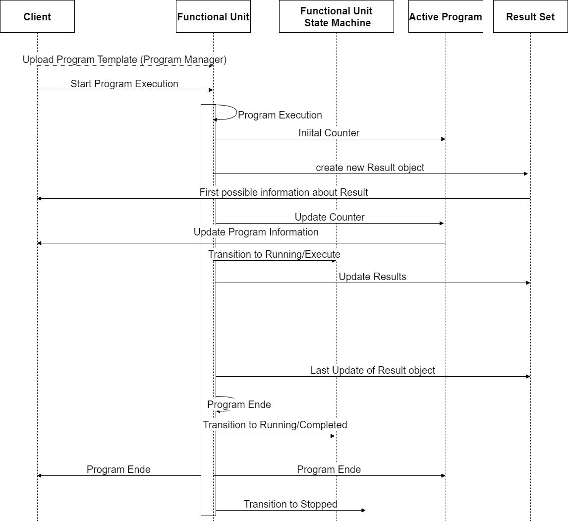
4.1.4 Program and result lifetime of a LADS Device
The lifetime of a program, from uploading a program template to the creation of the result, including additional information about the ActiveProgramType and the RunningStateMachineType, is as follows:
Uploading Program Template: The client uploads the ProgramTemplate to the ProgramTemplateSet of the ProgramManager using the Upload Method.
Starting the Program Execution: The program can be started either externally by a Client application using the Start or StartProgram Method or internally by the Device itself based on internal/process reasons.
Program Execution: The program execution progresses through various states defined in the FunctionalStateMachineType. During program execution, the ActiveProgramType provides information about the current state and runtime of the program. The CurrentPauseTime and CurrentRuntime properties indicate the current pause time and runtime of the program run, respectively. The CurrentStepName and CurrentStepNumber properties provide information about the current step being executed. The EstimatedRuntime, EstimatedStepNumbers, and EstimatedStepRuntime properties provide estimated information about the program's total runtime and steps.
Creating Results: As the program is executed, the FunctionalUnit generates data and results during the run. These results are collected in a result object which is managed in the ResultSet, which includes information about the program's initiator, the template used with additional parameters, samples, and contextual information to link and trace the results. The result object can provide the results either as files in the FileSet or as OPC UA variables in the VariableSet.
Program Completion: The program execution continues until it reaches the completion state (e.g., complete state) in the RunningStateMachineType. Once the program is complete, the results in the ResultSet are considered complete and are available for further processing and analysis.
Please note that the program's lifetime and states may vary based on the specific implementation and context of the OPC UA Companion Specification being used. The provided overview is a general outline of the program's lifetime and the high-level information about the ActiveProgramType and ResultSet based on the description provided.
This is illustrated in Figure 4
4.2 Introduction to OPC Unified Architecture
4.2.1 What is OPC UA?
OPC UA is an open and royalty free set of standards designed as a universal communication protocol. While there are numerous communication solutions available, OPC UA has key advantages:
A state-of-the-art security model (see OPC 10000-2).
A fault-tolerant communication protocol.
An information modelling framework that allows application developers to represent their data in a way that makes sense to them.
OPC UA has a broad scope which delivers economies of scale for application developers. This means that a larger number of high-quality applications are available at a reasonable cost. When combined with semantic models such as LADS, OPC UA makes it easier for end users to access data via generic commercial applications.
The OPC UA model is scalable from small devices to ERP systems. OPC UA Servers process information locally and then provide that data in a consistent format to any application requesting data - ERP, MES, PMS, maintenance systems, HMI, smartphone, or a standard browser, for example. For a more complete overview see OPC 10000-1
4.2.2 Basics of OPC UA
As an open standard, OPC UA is based on standard internet technologies, like TCP/IP, HTTP, Web Sockets.
As an extensible standard, OPC UA provides a set of Services (see OPC 10000-4) and a basic information model framework. This framework provides an easy means for creating and exposing vendor-defined information in a standard way. More importantly all OPC UA Clients are expected to be able to discover and use vendor-defined information. This means OPC UA users can benefit from the economies of scale that come with generic visualisation and historian applications. This specification is an example of an OPC UA Information Model designed to meet the needs of developers and users.
OPC UA Clients can be any consumer of data, from another Device on the network to browser-based thin clients and ERP systems. The full scope of OPC UA applications is shown in Figure 5.

OPC UA provides a robust and reliable communication infrastructure with mechanisms for handling lost messages, failover, heartbeat, etc. With its binary encoded data, it offers a high-performing data exchange solution. Security is built into OPC UA as security requirements become more and more important, especially since environments are connected to the office network or the internet and attackers are starting to focus on automation systems.
4.2.3 Information Modelling in OPC UA
4.2.3.1 Concepts
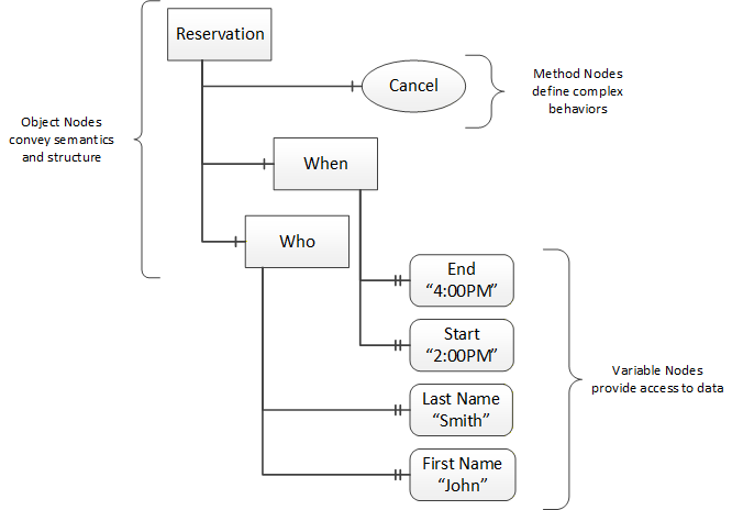
OPC UA provides a framework that can be used to represent complex information as Objects in an AddressSpace which can be accessed with standard services. These Objects consist of Nodes connected by References. Different classes of Nodes convey different semantics. For example, a Variable Node represents a value that can be read or written. The Variable Node has an associated DataType that can define the actual value, such as a string, float, structure etc. It can also describe the Variable value as a variant. A Method Node represents a Function that can be called. Every Node has a number of Attributes, including a unique identifier called a NodeId and non-localized name called a BrowseName. An Object representing a "Reservation" is shown in Figure 6.
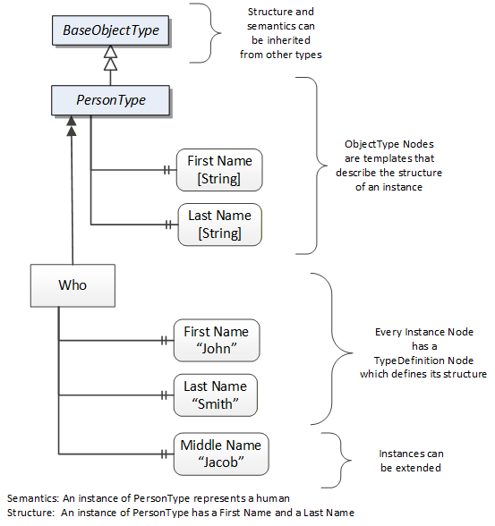
Object and Variable Nodes represent instances and always reference a TypeDefinition (ObjectType or VariableType) Node which describes their semantics and structure. Figure 7 illustrates the relationship between an instance and its TypeDefinition.
Type Nodes are templates that define all the children that can be present in an instance of the type. In the example in Figure 7 the "PersonType" ObjectType defines two children: First Name and Last Name. All instances of "PersonType" are expected to have the same children with the same BrowseNames. Within a type, the BrowseNames uniquely identify the children. This means Client applications can be designed to search for children based on the BrowseNames from the type instead of NodeIds. This eliminates the need for manual reconfiguration of systems if a Client uses types that are implemented on multiple Servers.
OPC UA also supports the concept of subtyping. This allows a modeller to take an existing type and extend it. Rules regarding subtyping are defined in OPC 10000-3, but in general they allow the extension of a given type or the restriction of a DataType. For example, the modeller may decide that the existing ObjectType needs an additional Variable in some cases. The modeller can create a subtype of the ObjectType and add the Variable. A Client that is expecting the parent type can treat the new type as if it were of the parent type. Regarding DataTypes, subtypes can only restrict. If a Variable is defined to have a numeric value, a subtype could restrict it to a float.
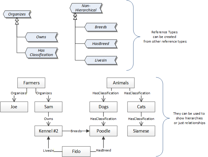
References allow Nodes to be connected in ways that describe their relationships. All References have a ReferenceType that specifies the semantics of the relationship. References can be hierarchical or non-hierarchical. Hierarchical references are used to create the structure of Objects and Variables, non-hierarchical references are used to create arbitrary associations. Applications can define their own ReferenceType by creating subtypes of an existing ReferenceType. Subtypes inherit the semantics of the parent but may add additional restrictions. Figure 8 depicts several References connecting different Objects.
The figures above use a notation that was developed for the OPC UA specification. This notation is summarized in Figure 9. UML representations can also be used; however, the OPC UA notation is less ambiguous because there is a direct mapping from the elements in the figures to Nodes in the AddressSpace of an OPC UA Server.

A complete description of the different types of Nodes and References can be found in OPC 10000-3 and the base structure is described in OPC 10000-5.
The OPC UA specification defines a very wide range of functionalities in its basic information model. It is not required that all Clients or Servers support all functionalities in the OPC UA specifications. OPC UA includes the concept of Profiles, which segment the functionality into testable certifiable units. This allows the definition of functional subsets (that are expected to be implemented) within a companion specification. Profiles do not restrict functionality, but they generate requirements for a minimum set of functionalities (see OPC 10000-7).
4.2.3.2 Namespaces
OPC UA allows information from many different sources to be combined into a single coherent AddressSpace. Namespaces make this possible by eliminating naming and ID conflicts between information from different sources. Each Namespace in OPC UA has a globally unique string called a NamespaceUri which identifies a naming authority, and a locally unique integer called a NamespaceIndex which is an index into the Server's table of NamespaceUris. The NamespaceIndex is unique only within the context of a Session between an OPC UA Client and an OPC UA Server - the NamespaceIndex can change between Sessions and still identify the same item even though the NamespaceUri's location in the table has changed. The Services defined for OPC UA use the NamespaceIndex to specify the Namespace for qualified values.
There are two types of structured values in OPC UA that are qualified with NamespaceIndexes: NodeIds and QualifiedNames. NodeIds are locally unique (and sometimes globally unique) identifiers for Nodes. The same globally unique NodeId can be used as the identifier in a Node in many Servers - the Node's instance data may vary but its semantic meaning is the same regardless of the Server it appears in. This means Clients can have built-in knowledge of what the data means in these Nodes. OPC UA Information Models generally define globally unique NodeIds for the TypeDefinitions defined by the Information Model.
QualifiedNames are non-localized names qualified with a Namespace. They are used for the BrowseNames of Nodes and allow the same names to be used by different information models without conflict. TypeDefinitions are not allowed to have children with duplicate BrowseNames; however, instances do not have that restriction.
4.2.3.3 Companion Specifications
An OPC UA companion specification for an industry-specific vertical market describes an Information Model by defining ObjectTypes, VariableTypes, DataTypes and ReferenceTypes that represent the concepts used in the vertical market, as well as potentially well-defined Objects as entry points into the AddressSpace.