LADS, an acronym for Laboratory and Analytical Device Standard, is a manufacturer-independent, open standard for analytical and laboratory equipment. It comprehensively encapsulates various customer industries and their respective workflows, providing a sustainable application that also caters to the future demands of digitalization and automation. LADS is built upon OPC UA, an open communication platform developed and promoted by the international non-profit OPC Foundation. OPC UA facilitates cross-vendor communication and interoperability in industrial automation processes.
The benefits of the LADS standard are listed below:
Manufacturer-independent standard
Open standard, capable of integrating instruments in different workflows
Plug and play interoperability of Lab and Analytical Devices
Covers a wide range of different Lab and Analytical devices through device-type-agnostic design principles
Future versions may allow machine-readable semantic contextualization of LADS patterns by linking nodes within the information model to suitable taxonomies and ontologies (utilizing Dictionary References OPC 10000-19)
The Laboratory and Analytical Device Standard (LADS) Companion Specification provides a comprehensive framework for modelling and managing analytical and laboratory equipment. It does this by defining two primary views: the Hardware View and the Functional View.
The Hardware View focuses on the physical aspects of the devices and their components. This view is essential for various use cases related to asset management, including enhanced serviceability.
Key features of the Hardware View are introduced in the following subsections.
These are modelled with properties such as nameplates, installation dates, condition monitoring, and calibration & validation status.
Hardware components like the Lid, Rotor, Drive, and Compressor are modelled in a sub-tree. Each component exposes its individual nameplate and maintenance-related information, similar to the device itself, and can also have components itself.
Recurrent tasks that affect either the entire device or individual components (such as inspection, maintenance, calibration, validation, cleaning, etc.) can be organized via LADS.
Figure 1 shows a centrifuge, including various components and the corresponding component data.
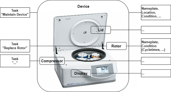
Figure 1 – Hardware View of a centrifuge
The Functional View deals with data relevant for the operation, automation, and orchestration of an instrument.
Key aspects of the Functional View are introduced in the following subsections.
Actions to achieve a specific outcome. (Typical functions include but are not limited to sensors, controllers, actuators, timers, etc. They may utilize one or more tangible components.)
The complete list of Functions can be found in section 7.4
Figure 2 shows a centrifuge, including various components and the corresponding component data.
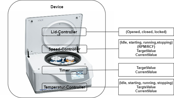
Figure 2 – Function View of a centrifuge
Many laboratory and analytical devices allow the user to define and run programs, also called methods. The Program Manager organizes program templates, runs programs, and manages the result data generated during a run, providing device-level orchestration.
Functional Units are aggregations of functions designed to achieve a specific outcome. Typically, a Functional Unit is utilized by only one user at a time and exposes its current state. It may optionally include a Program Manager. A Functional Unit can be seen as a virtual device within a LADS Device, grouping together several (potentially redundant) functions. This concept is particularly useful when a LADS Device contains multiple functions that can be grouped as virtual devices or behave as separate devices. In such cases, a LADS Device can be divided into multiple Functional Units, with each Functional Unit representing a virtual device.
For instance, consider a bioreactor vessel with two separate interfaces (see Figure 3). Each container has its own functions, such as a temperature sensor and a motor, and its own program. This setup allows the bioreactor to be split into two Functional Units, each representing a separate container with its own program and set of functions.
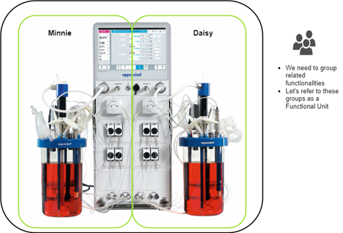
Figure 3 – Example of a LADS Device with two Functional Units
This section provides an overview of the state machines and device status variables used in the LADS Companion Specification. It explains the relationship between various state machines and status variables in the context of a LADS Device, its Components, and Functional Units.
The relationship between these state machines and status variables is crucial for understanding the operation and management of a LADS Device. The state of the LADS Device state machine and the FunctionalUnit state machines come first and form the basis for the MachineryItemState. The MachineryOperationMode provides additional context about the type of Tasks being performed. The DeviceHealth and DeviceHealthAlarms provide information about the device's condition and any Alarms that may have been triggered.
Refer to Annex B for proposed mappings between the DeviceStateMachine, the FunctionalUnit state machines, the MachineryItemState and the DeviceHealth.
The DeviceStateMachine provides a domain-specific view of the device's state. It reflects the condition of the Device itself.
The MachineryItemState provides a harmonized state machine across various domains, particularly in mechanical engineering. It serves as a semantic stack light, providing a high-level system with a quick overview of the device's operational status.
The MachineryOperationMode indicates the type of Tasks being performed by the Device. It may not be known by the MachineryItem itself and might need to be provided by an external source, like an MES system or the operator.
Each FunctionalUnit within a LADS Device has an independent FunctionalUnit state machine. For instance, a device with three FunctionalUnits will have three separate FunctionalUnit state machines. These state machines are process oriented and can operate independently. They may also include sub-state machines for the running state. These state machines come first, and their states form the basis for the MachineryItemState.
ControlFunctions also have a FunctionStateMachine, similar to the FunctionalUnitStateMachine. This state machine provides a detailed view of the operational state of the ControlFunctions.
The DeviceHealth and DeviceHealthAlarms provide information about the device's condition and any Alarms that may have been triggered. They are optional and can be implemented at both the Device and Component levels. The DeviceHealth status variable provides a quick overview of the device's health status, while the DeviceHealthAlarms variable provides detailed information about any specific Alarms that may have been triggered.
The lifetime of a program, from uploading a program template to the creation of the result, including additional information about the ActiveProgramType and the RunningStateMachineType, is as follows:
- Uploading Program Template: The client uploads the ProgramTemplate to the ProgramTemplateSet of the ProgramManager using the Upload Method.
- Starting the Program Execution: The program can be started either externally by a Client application using the Start or StartProgram Method or internally by the Device itself based on internal/process reasons.
- Program Execution: The program execution progresses through various states defined in the FunctionalStateMachineType. During program execution, the ActiveProgramType provides information about the current state and runtime of the program. The CurrentPauseTime and CurrentRuntime properties indicate the current pause time and runtime of the program run, respectively. The CurrentStepName and CurrentStepNumber properties provide information about the current step being executed. The EstimatedRuntime, EstimatedStepNumbers, and EstimatedStepRuntime properties provide estimated information about the program's total runtime and steps.
- Creating Results: As the program is executed, the FunctionalUnit generates data and results during the run. These results are collected in a result object which is managed in the ResultSet, which includes information about the program's initiator, the template used with additional parameters, samples, and contextual information to link and trace the results. The result object can provide the results either as files in the FileSet or as OPC UA variables in the VariableSet.
- Program Completion: The program execution continues until it reaches the completion state (e.g., complete state) in the RunningStateMachineType. Once the program is complete, the results in the ResultSet are considered complete and are available for further processing and analysis.
Please note that the program's lifetime and states may vary based on the specific implementation and context of the OPC UA Companion Specification being used. The provided overview is a general outline of the program's lifetime and the high-level information about the ActiveProgramType and ResultSet based on the description provided.
This is illustrated in Figure 4
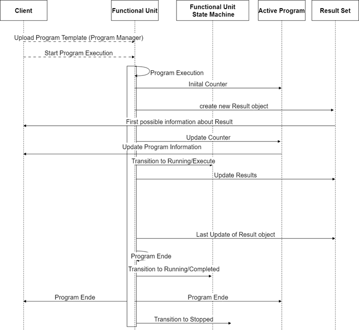
Figure 4 – Simplified program sequence