The CASType is the representation of a Compressed Air System and provides both Objects for Quantities and FunctionalGroups for its Airnets, Components, and the Main Control System. It is illustrated in Figure 16 and formally defined in Table 11.
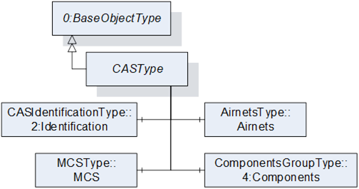
Figure 16 – CASType Illustration
|
Attribute |
Value |
||||
|
BrowseName |
CASType |
||||
|
IsAbstract |
False |
||||
|
References |
Node Class |
BrowseName |
DataType |
TypeDefinition |
Other |
|
Subtype of the 0:BaseObjectType defined in OPC 10000-5. |
|||||
|
0:HasComponent |
Object |
Airnets |
|
AirnetsType |
O |
|
0:HasComponent |
Object |
4:Components |
|
ComponentsGroupType |
O |
|
0:HasComponent |
Object |
2:Identification |
|
CASIdentificationType |
O |
|
0:HasComponent |
Object |
MCS |
|
MCSType |
O |
The CASType ObjectType is a concrete type and shall be used directly.
The optional Object Airnets organizes all available Airnets.
The optional Object Components organizes all installed Components by their ComponentClasses.
The optional FunctionalGroup Identification provides Properties to identify a Compressed Air System.
The optional Object MCS is the representation of the Main Control System.
The InstanceDeclarations of the CASType have additional Attributes defined in Table 12.
Table 12 – CASType Attribute values for child Nodes
|
Source Path |
Description Attribute |
|
Airnets |
All airnets in a compressed air system as browsable objects. |
|
4:Components |
All components in a compressed air system as browsable objects. |
|
2:Identification |
Identification properties of the compressed air system. |
|
MCS |
Representation of the MCS in a compressed air system. |
Figure 17 shows a usage example for the instantiation of an arbitrary Compressed Air System that has two Airnets, two compressors, one dryer, and two valves. The Airnets share CompressorX.
For each DeviceClass connected to the Compressed Air System, there is one ComponentGroup Object in the Components Object of the CompressedAirSystem Object. The instances of the compressors, valves, and the dryer are children of these Objects.
Both Airnets have a Components Object, just like the CompressedAirSystem Object. For each DeviceClass connected to an Airnet, there is one ComponentGroup Object in the Components Object of that Airnet. Connected Components are referenced by an Organizes reference.
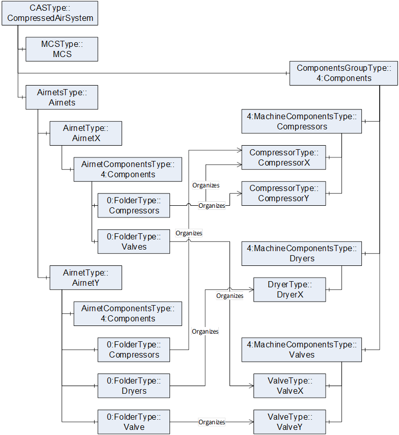
Figure 17 – CASType Components Reference Instantiation Example
The AirnetsType enables the grouping of Airnets. It is formally defined in Table 13.
Table 13 – AirnetsType Definition
|
Attribute |
Value |
||||
|
BrowseName |
AirnetsType |
||||
|
IsAbstract |
False |
||||
|
References |
Node Class |
BrowseName |
DataType |
TypeDefinition |
Other |
|
Subtype of the 4:MachineComponentsType defined in OPC 40001-1, i.e. inheriting the InstanceDeclarations of that Node. |
|||||
|
|
|
|
|
|
|
|
The following nodes override nodes added by the 4:MachineComponentsType |
|||||
|
0:HasProperty |
Variable |
0:DefaultInstanceBrowseName |
0:QualifiedName |
0:PropertyType |
|
|
0:HasComponent |
Object |
4:<Component> |
|
AirnetType |
OP |
The InstanceDeclarations of the AirnetsType have additional Attributes defined in Table 14.
Table 14 – AirnetsType Attribute values for child Nodes
|
Source Path |
Value Attribute |
Description Attribute |
|
0:DefaultInstanceBrowseName |
“Airnets” |
The default BrowseName for instances of the type. |
|
4:<Component> |
|
Represents of an airnet. |
The ComponentsGroupType enables the grouping of Components and can be nested. It is illustrated in Figure 18 and formally defined in Table 15.
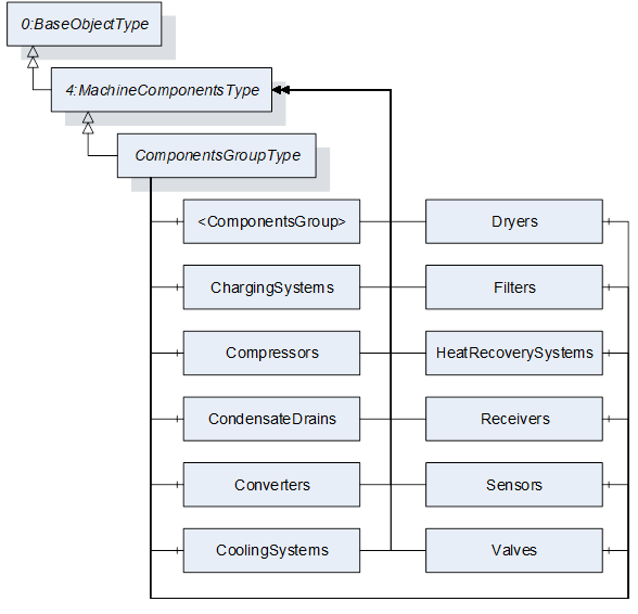
Figure 18 – ComponentsGroupType Illustration
Table 15 – ComponentsGroupType Definition
|
Attribute |
Value |
||||
|
BrowseName |
ComponentsGroupType |
||||
|
IsAbstract |
False |
||||
|
References |
Node Class |
BrowseName |
DataType |
TypeDefinition |
Other |
|
Subtype of the 4:MachineComponentsType defined in OPC 40001-1, i.e. inheriting the InstanceDeclarations of that Node. |
|||||
|
0:HasComponent |
Object |
<ComponentsGroup> |
|
4:MachineComponentsType |
OP |
|
0:HasComponent |
Object |
ChargingSystems |
|
4:MachineComponentsType |
O |
|
0:HasComponent |
Object |
Compressors |
|
4:MachineComponentsType |
O |
|
0:HasComponent |
Object |
CondensateDrains |
|
4:MachineComponentsType |
O |
|
0:HasComponent |
Object |
CondensateSeparators |
|
4:MachineComponentsType |
O |
|
0:HasComponent |
Object |
Converters |
|
4:MachineComponentsType |
O |
|
0:HasComponent |
Object |
CoolingSystems |
|
4:MachineComponentsType |
O |
|
0:HasComponent |
Object |
Dryers |
|
4:MachineComponentsType |
O |
|
0:HasComponent |
Object |
Filters |
|
4:MachineComponentsType |
O |
|
0:HasComponent |
Object |
HeatRecoverySystems |
|
4:MachineComponentsType |
O |
|
0:HasComponent |
Object |
Receivers |
|
4:MachineComponentsType |
O |
|
0:HasComponent |
Object |
Sensors |
|
4:MachineComponentsType |
O |
|
0:HasComponent |
Object |
Valves |
|
4:MachineComponentsType |
O |
The OptionalPlaceholder Object <ComponentsGroup> allows nesting this ObjectType to further categorize the referenced Components. It also allows adding concrete Component groups not defined by this specification.
The InstanceDeclarations of the ComponentsGroupType have additional Attributes defined in Table 16.
Table 16 – ComponentsGroupType Attribute values for child Nodes
|
SourcePath |
Description Attribute |
|
<ComponentsGroup> |
All components of a specific type in a compressed air system as browsable objects. |
|
ChargingSystems |
Organizes all charging systems connected to the compressed air system. |
|
Compressors |
Organizes all compressors connected to the compressed air system. |
|
CondensateDrains |
Organizes all condensate drains connected to the compressed air system. |
|
CondensateSeparators |
Organizes all condensate separators connected to the compressed air system. |
|
Converters |
Organizes all converters connected to the compressed air system. |
|
CoolingSystems |
Organizes all cooling systems connected to the compressed air system. |
|
Dryers |
Organizes all dryers connected to the compressed air system. |
|
Filters |
Organizes all filters connected to the compressed air system. |
|
HeatRecoverySystems |
Organizes all heat recovery systems connected to the compressed air system. |
|
Receivers |
Organizes all receivers connected to the compressed air system. |
|
Sensors |
Organizes all sensors connected to the compressed air system. |
|
Valves |
Organizes all valves connected to the compressed air system. |
The AirnetType is the representation of an Airnet and provides both Objects for Quantities and FunctionalGroups. It is illustrated in Figure 19 and formally defined in Table 17.
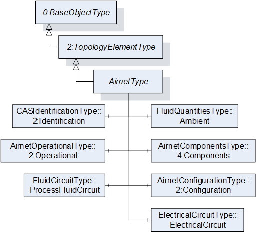
Figure 19 – AirnetType Illustration
Table 17 – AirnetType Definition
|
Attribute |
Value |
||||
|
BrowseName |
AirnetType |
||||
|
IsAbstract |
False |
||||
|
References |
Node Class |
BrowseName |
DataType |
TypeDefinition |
Other |
|
Subtype of the 2:TopologyElementType defined in OPC 10000-100, i.e. inheriting the InstanceDeclarations of that Node. |
|||||
|
0:HasComponent |
Object |
Ambient |
|
FluidQuantitiesType |
O |
|
0:HasComponent |
Object |
4:Components |
|
AirnetComponentsType |
O |
|
0:HasComponent |
Object |
2:Configuration |
|
AirnetConfigurationType |
O |
|
0:HasComponent |
Object |
ElectricalCircuit |
|
ElectricalCircuitType |
O |
|
0:HasComponent |
Object |
2:Operational |
|
AirnetOperationalType |
O |
|
0:HasComponent |
Object |
ProcessFluidCircuit |
|
FluidCircuitType |
O |
|
|
|
|
|
|
|
|
The following nodes override nodes added by the 2:TopologyElementType |
|||||
|
0:HasComponent |
Object |
2:Identification |
|
CASIdentificationType |
M |
The optional Object Ambient provides Quantities for the ambient air conditions at an Airnet. Of the optional Variables of the FluidQuantitiesType only AbsolutePressure, DewPoint, RelativeHumidity, and Temperature are available.
The optional Folder Components provides Folders for organizing Components connected to the Airnet. Usually, the Components are grouped by their DeviceClass and shall be referenced by using the Organizes ReferenceType. The concrete instance of a Component shall be instantiated in the Components Folder of the CASType instance.
Figure 20 shows an example on how to instantiate the FunctionalGroup Components for an Airnet in the AddressSpace of an OPC UA Server.
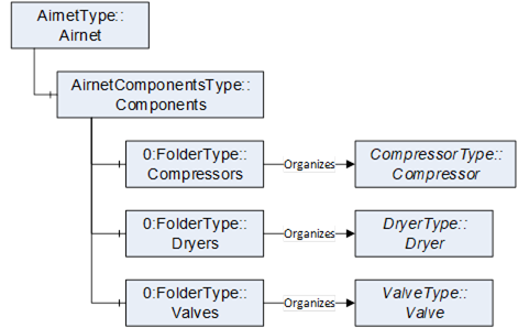
Figure 20 – Airnet Components Example
The optional FunctionalGroup Configuration provides Variables for configuring the behavior of an Airnet.
The optional Object ElectricalCircuit provides Quantities for the electrical ports of an Airnet.
The mandatory FunctionalGroup Identification provides Properties to identify an Airnet.
The optional FunctionalGroup Operational provides Variables for process data used during normal operation of an Airnet, such as measurements, efficiencies, and states.
The optional Object ProcessFluidCircuit provides static design information about the process fluid as well as Quantities for the process fluids inlets, outlets, and delta of an Airnet.
The InstanceDeclarations of the AirnetType have additional Attributes defined in Table 18.
Table 18 – AirnetType Attribute values for child Nodes
|
Source Path |
Value Attribute |
Description Attribute |
||
|
Ambient |
|
Measurements and calculations of ambient air at the topology element. |
||
|
|
|
Measured or calculated actual absolute pressure of the environment in which the component, piping or system is working. |
||
|
|
|
Measured or calculated actual dew point of the environment in which the component, piping or system is working. |
||
|
|
|
Measured or calculated actual relative humidity of the environment in which the component, piping or system is working. |
||
|
|
|
Measured or calculated actual temperature of the environment in which the component, piping or system is working. |
||
|
4:Components |
|
Organizes components assigned to the airnet. |
||
|
2:Configuration |
|
Configure the behavior of the topology element. |
||
|
ElectricalCircuit |
|
Measurements and calculations of the electrical ports and delta of the topology element. |
||
|
2:Identification |
|
Identification properties of the topology element. |
||
|
2:Operational |
|
Data for normal operation of the topology element. |
||
|
ProcessFluidCircuit |
|
Measurements and calculations of the process fluid ports and delta of the topology element. |
||
|
|
|
Enumeration of possible process fluid types. |
The AirnetComponentsType enables the grouping of Airnets. It is formally defined in Table 19.
Table 19 – AirnetComponentsType Definition
|
Attribute |
Value |
||||
|
BrowseName |
AirnetComponentsType |
||||
|
IsAbstract |
False |
||||
|
References |
Node Class |
BrowseName |
DataType |
TypeDefinition |
Other |
|
Subtype of the 0:FolderType defined in OPC 10000-5. |
|||||
|
0:HasComponent |
Object |
<ComponentsGroup> |
|
0:FolderType |
OP |
|
0:HasComponent |
Object |
ChargingSystems |
|
0:FolderType |
O |
|
0:HasComponent |
Object |
Compressors |
|
0:FolderType |
O |
|
0:HasComponent |
Object |
CondensateDrains |
|
0:FolderType |
O |
|
0:HasComponent |
Object |
CondensateSeparators |
|
0:FolderType |
O |
|
0:HasComponent |
Object |
Converters |
|
0:FolderType |
O |
|
0:HasComponent |
Object |
CoolingSystems |
|
0:FolderType |
O |
|
0:HasComponent |
Object |
Dryers |
|
0:FolderType |
O |
|
0:HasComponent |
Object |
Filters |
|
0:FolderType |
O |
|
0:HasComponent |
Object |
HeatRecoverySystems |
|
0:FolderType |
O |
|
0:HasComponent |
Object |
Receivers |
|
0:FolderType |
O |
|
0:HasComponent |
Object |
Sensors |
|
0:FolderType |
O |
|
0:HasComponent |
Object |
Valves |
|
0:FolderType |
O |
The OptionalPlaceholder Object <ComponentsGroup> allows adding concrete Component groups not defined by this specification.
The InstanceDeclarations of the AirnetComponentsType have additional Attributes defined in Table 20.
Table 20 – AirnetComponentsType Attribute values for child Nodes
|
Source Path |
Description Attribute |
|
<ComponentsGroup> |
All components of a specific type connected to the airnet. |
|
ChargingSystems |
Organizes all charging systems connected to the airnet. |
|
Compressors |
Organizes all compressors connected to the airnet. |
|
CondensateDrains |
Organizes all condensate drains connected to the airnet. |
|
CondensateSeparators |
Organizes all condensate separators connected to the airnet. |
|
Converters |
Organizes all converters connected to the airnet. |
|
CoolingSystems |
Organizes all cooling systems connected to the airnet. |
|
Dryers |
Organizes all dryers connected to the airnet. |
|
Filters |
Organizes all filters connected to the airnet. |
|
HeatRecoverySystems |
Organizes all heat recovery systems connected to the airnet. |
|
Receivers |
Organizes all receivers connected to the airnet. |
|
Sensors |
Organizes all sensors connected to the airnet. |
|
Valves |
Organizes all valves connected to the airnet. |
The MCSType is the representation of a Main Control System and provides both Objects for Quantities and FunctionalGroups. It is illustrated in Figure 21 and formally defined in Table 21.
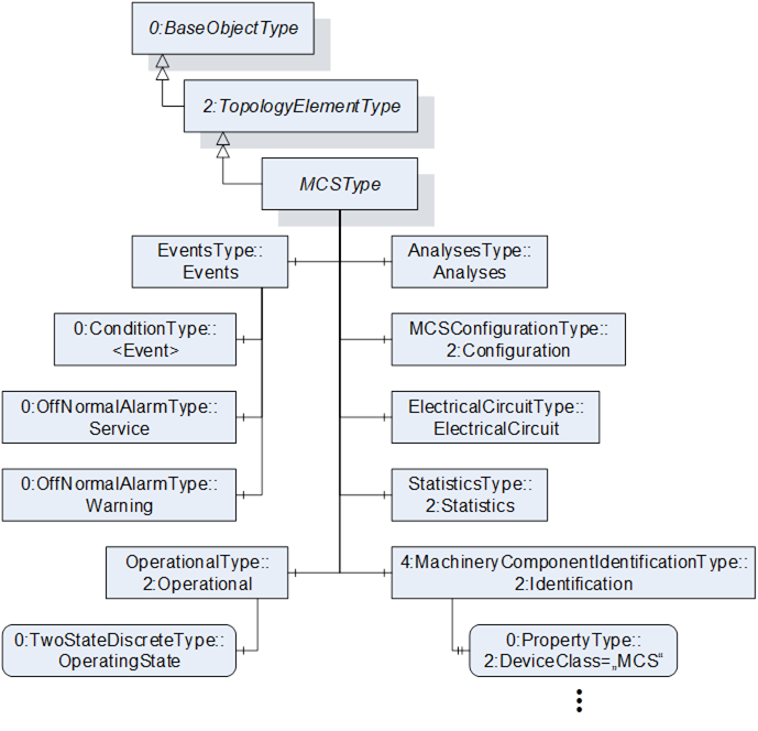
Figure 21 – MCSType Illustration
|
Attribute |
Value |
||||
|
BrowseName |
MCSType |
||||
|
IsAbstract |
False |
||||
|
References |
Node Class |
BrowseName |
DataType |
TypeDefinition |
Other |
|
Subtype of the 2:TopologyElementType defined in OPC 10000-100, i.e. inheriting the InstanceDeclarations of that Node. |
|||||
|
0:HasComponent |
Object |
Analyses |
|
AnalysesType |
O |
|
0:HasComponent |
Object |
2:Configuration |
|
MCSConfigurationType |
O |
|
0:HasComponent |
Object |
ElectricalCircuit |
|
ElectricalCircuitType |
O |
|
0:HasComponent |
Object |
Events |
|
EventsType |
O |
|
0:HasComponent |
Object |
2:Operational |
|
OperationalType |
O |
|
0:HasComponent |
Object |
2:Statistics |
|
StatisticsType |
O |
|
|
|
|
|
|
|
|
The following nodes override nodes added by the 2:TopologyElementType |
|||||
|
0:HasComponent |
Object |
2:Identification |
|
4:MachineryComponentIdentificationType |
M |
The optional FunctionalGroup Analyses provides Objects and Methods for analyses that can be invoked on the Main Control System.
The optional FunctionalGroup Configuration provides Objects and Methods for configuring the behavior of the Main Control System.
The optional Object ElectricalCircuit provides Quantities for the electrical input of the Main Control System.
The optional FunctionalGroup Events provides Objects for alarms and conditions of the Main Control System. Of the available optional Objects in the EventsType, only Service and Warning are instantiated.
The mandatory FunctionalGroup Identification provides Properties to identify the Main Control System. The optional Variable DeviceClass has its ModellingRule changed to mandatory and its Value Attribute set to a specific value.
The optional FunctionalGroup Operational provides Variables for process data used during normal operation of the Main Control System, such as measurements, efficiencies, and states.
The optional FunctionalGroup Statistics provides Variables for statistical applications of the Main Control System, such as counters.
The InstanceDeclarations of the MCSType have additional Attributes defined in Table 22.
Table 22 – MCSType Attribute values for child Nodes
|
Source Path |
Value Attribute |
Description Attribute |
||
|
Analyses |
|
Invokable analyses for the topology element. |
||
|
2:Configuration |
|
Configure the behavior of the topology element. |
||
|
ElectricalCircuit |
|
Measurements and calculations of the electrical ports and delta of the topology element. |
||
|
Events |
|
Alarms and conditions of the topology element. |
||
|
2:Identification |
|
Identification properties of the topology element. |
||
|
|
“MCS” |
Domain or for what purpose this item is used. |
||
|
2:Operational |
|
Data for normal operation of the topology element. |
||
|
2:Statistics |
|
Data for statistics applications for the topology element. |
The CASComponentType is the representation of a Component and provides both Objects for Quantities and FunctionalGroups. It is illustrated in Figure 22 and formally defined in Table 23.
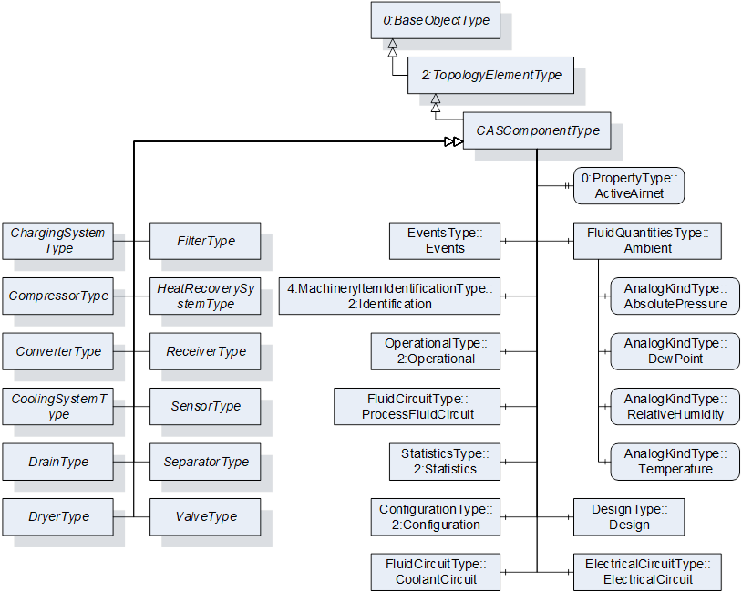
Figure 22 – CASComponentType Illustration
Table 23 – CASComponentType Definition
|
Attribute |
Value |
||||
|
BrowseName |
CASComponentType |
||||
|
IsAbstract |
False |
||||
|
References |
Node Class |
BrowseName |
DataType |
TypeDefinition |
Other |
|
Subtype of the 2:TopologyElementType defined in OPC 10000-100, i.e. inheriting the InstanceDeclarations of that Node. |
|||||
|
0:HasSubtype |
ObjectType |
ChargingSystemType |
Defined in 7.8 |
||
|
0:HasSubtype |
ObjectType |
CompressorType |
Defined in 7.9 |
||
|
0:HasSubtype |
ObjectType |
ConverterType |
Defined in 7.10 |
||
|
0:HasSubtype |
ObjectType |
CoolingSystemType |
Defined in 7.11 |
||
|
0:HasSubtype |
ObjectType |
DrainType |
Defined in 7.12 |
||
|
0:HasSubtype |
ObjectType |
DryerType |
Defined in 7.13 |
||
|
0:HasSubtype |
ObjectType |
FilterType |
Defined in 7.14 |
||
|
0:HasSubtype |
ObjectType |
HeatRecoverySystemType |
Defined in 7.15 |
||
|
0:HasSubtype |
ObjectType |
ReceiverType |
Defined in 7.16 |
||
|
0:HasSubtype |
ObjectType |
SensorType |
Defined in 7.17 |
||
|
0:HasSubtype |
ObjectType |
SeparatorType |
Defined in 7.18 |
||
|
0:HasSubtype |
ObjectType |
ValveType |
Defined in 7.19 |
||
|
|
|
|
|
|
|
|
0:HasProperty |
Variable |
ActiveAirnet |
0:NodeId |
0:PropertyType |
O, RW |
|
0:HasComponent |
Object |
Ambient |
|
FluidQuantitiesType |
O |
|
0:HasComponent |
Object |
2:Configuration |
|
ConfigurationType |
O |
|
0:HasComponent |
Object |
CoolantCircuit |
|
FluidCircuitType |
O |
|
0:HasComponent |
Object |
Design |
|
DesignType |
O |
|
0:HasComponent |
Object |
ElectricalCircuit |
|
ElectricalCircuitType |
O |
|
0:HasComponent |
Object |
Events |
|
EventsType |
O |
|
0:HasComponent |
Object |
2:Operational |
|
OperationalType |
O |
|
0:HasComponent |
Object |
ProcessFluidCircuit |
|
FluidCircuitType |
O |
|
0:HasComponent |
Object |
2:Statistics |
|
StatisticsType |
O |
|
|
|
|
|
|
|
|
The following nodes override nodes added by the 2:TopologyElementType |
|||||
|
0:HasComponent |
Object |
2:Identification |
|
M |
|
The optional Property ActiveAirnet indicates which Airnet is currently using this Component. The Property shall only be instantiated if the Component is connected to more than one Airnet.
The optional Object Ambient provides Quantities for the ambient air conditions at a Component. Of the optional Variables of the FluidQuantitiesType only AbsolutePressure, DewPoint, RelativeHumidity, and Temperature are instantiated.
The optional FunctionalGroup Configuration provides a framework for properties aimed at configuring the behavior of a Component in a Compressed Air System.
The optional Object CoolantCircuit provides design information about the coolant used as well as measurements and calculations for the inlet, outlet, and delta of coolant conditions on a Component in a Compressed Air System.
The optional FunctionalGroup Design provides static design properties of a Component in a Compressed Air System and acts as a framework for design properties in general.
The optional Object ElectricalCircuit provides measurements and calculations for the electrical input, output, and delta of a Component in a Compressed Air System.
The optional FunctionalGroup Events provides instances of common conditions of a Component in a Compressed Air System. It also provides a framework for instantiating conditions in the AddressSpace. If the server is not capable of instantiating ConditionTypes, this group shall not be instantiated.
The mandatory FunctionalGroup Identification provides capabilities to identify a Component in a Compressed Air System.
The optional FunctionalGroup Operational provides properties for process data used during normal operation of a Component, such as measurements, efficiencies, and states.
The optional Object ProcessFluidCircuit provides design information about the process fluid processed as well as measurements and calculations for the inlet, outlet, and delta of process fluid conditions on a Component in a Compressed Air System.
The optional FunctionalGroup Statistics provides properties for statistics applications of a Component in a Compressed Air System, like counters.
The optional Property DeviceClass of the MachineryItemIdentificationType is overridden. The ModellingRule is changed to mandatory and the Value Attribute is set to a specific value for each DeviceClass. When a concrete subtype of the MachineryItemIdentificationType is selected for a subtype or an instance of the CASComponentType, the ModellingRule of the DeviceClass Property shall remain as mandatory.
When instantiating the CASComponentType or one of its subtypes, the instantiated Object shall have at least one appropriate GeneratesEvent reference targeting the subtypes of the DeviceHealthDiagnosticAlarmType.
The components of the CASComponentType have additional subcomponents defined in Table 24.
Table 24 – CASComponentType Additional Subcomponents
|
Source Path |
References |
NodeClass |
BrowseName |
DataType |
TypeDefinition |
Other |
|
The following nodes override nodes added by the 4:MachineryItemIdentificationType |
||||||
|
2:Identification |
0:HasProperty |
Variable |
2:DeviceClass |
0:String |
0:PropertyType |
M, RO |
|
|
|
|
|
|
|
|
|
The following nodes override nodes added by the OperationalType |
||||||
|
2:Operational |
0:HasComponent |
Variable |
HealthState |
HealthStateEnum |
0:DataItemType |
O, RO |
|
2:Operational |
0:HasComponent |
Variable |
IntegratedState |
IntegratedStateEnum |
0:DataItemType |
O, RO |
|
2:Operational |
0:HasComponent |
Variable |
OperatingState |
OperatingStateEnum |
0:DataItemType |
O, RO |
The InstanceDeclarations of the CASComponentType have additional Attributes defined in Table 25.
Table 25 – CASComponentType Attribute values for child Nodes
|
Source Path |
Description Attribute |
||
|
ActiveAirnet |
Indicates which airnet is currently using this component. |
||
|
Ambient |
Measurements and calculations of ambient air at the topology element. |
||
|
|
Measured or calculated actual absolute pressure of the environment in which the component, piping or system is working. |
||
|
|
Measured or calculated actual dew point of the environment in which the component, piping or system is working. |
||
|
|
Measured or calculated actual relative humidity of the environment in which the component, piping or system is working. |
||
|
|
Measured or calculated actual temperature of the environment in which the component, piping or system is working. |
||
|
2:Configuration |
Configure the behavior of the topology element. |
||
|
CoolantCircuit |
Measurements and calculations of the coolant ports and delta of the topology element. |
||
|
|
Enumeration of possible coolant types. |
||
|
Design |
Static design properties of the topology element. |
||
|
ElectricalCircuit |
Measurements and calculations of the electrical ports and delta of the topology element. |
||
|
Events |
Alarms and conditions of the topology element. |
||
|
2:Identification |
Identification properties of the topology element. |
||
|
|
Domain or for what purpose this item is used. |
||
|
2:Operational |
Data for normal operation of the topology element. |
||
|
|
Actual health state of the component. |
||
|
|
Actual integrated state of the component. |
||
|
|
Actual operating state of the component. |
||
|
ProcessFluidCircuit |
Measurements and calculations of the process fluid ports and delta of the topology element. |
||
|
|
Enumeration of possible process fluid types. |
||
|
2:Statistics |
Data for statistics applications for the topology element. |
The ChargingSystemType shall be used as TypeDefinition for concrete charging system Objects and shall be used as supertype for concrete charging system ObjectTypes. A charging system is a pressure maintenance system that maintains a minimum pressure in a Component. It is formally defined in Table 26.
Table 26 – ChargingSystemType Definition
|
Attribute |
Value |
||||
|
BrowseName |
ChargingSystemType |
||||
|
IsAbstract |
False |
||||
|
References |
Node Class |
BrowseName |
DataType |
TypeDefinition |
Other |
|
Subtype of the CASComponentType defined in 7.7, i.e. inheriting the InstanceDeclarations of that Node. |
|||||
When instantiating this ObjectType the Identification Object shall use one of the concrete subtypes of the MachineryItemIdentificationType, either MachineIdentificationType or MachineryComponentIdentificationType, depending on the concrete usage of this Component. The ModellingRule of the Property DeviceClass remains as mandatory and its Value Attribute shall match the value stated in Table 9.
The CompressorType is the representation of a compressor and extends its supertype by specific Nodes. According to EN 1012-1/ISO/DIS 18623-1, a compressor compresses a gas or vapor media to a pressure higher than that at the inlet. It is illustrated in Figure 23 and formally defined in Table 27.
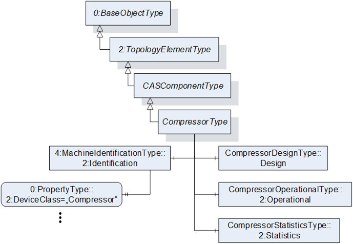
Figure 23 – CompressorType Illustration
Table 27 – CompressorType Definition
|
Attribute |
Value |
||||
|
BrowseName |
CompressorType |
||||
|
IsAbstract |
False |
||||
|
References |
Node Class |
BrowseName |
DataType |
TypeDefinition |
Other |
|
Subtype of the CASComponentType defined in 7.7, i.e. inheriting the InstanceDeclarations of that Node. |
|||||
|
|
|
|
|
|
|
|
The following nodes override nodes added by the CASComponentType |
|||||
|
0:HasComponent |
Object |
Design |
|
CompressorDesignType |
O |
|
0:HasComponent |
Object |
2:Identification |
|
4:MachineIdentificationType |
M |
|
0:HasComponent |
Object |
2:Operational |
|
CompressorOperationalType |
O |
|
0:HasComponent |
Object |
2:Statistics |
|
CompressorStatisticsType |
O |
The InstanceDeclarations of the CompressorType have additional Attributes defined in Table 28.
Table 28 – CompressorType Attribute values for child Nodes
|
Source Path |
Value Attribute |
Description Attribute |
||
|
|
“Compressor” |
Domain or for what purpose this item is used. |
The ConverterType is the representation of a converter and extends its supertype by specific Nodes. A converter eliminates hydrocarbons from a compressed air flow by catalytic reaction with oxygen into H2O and CO2. It is illustrated in Figure 24 and formally defined in Table 29.

Figure 24 – ConverterType Illustration
Table 29 – ConverterType Definition
|
Attribute |
Value |
||||
|
BrowseName |
ConverterType |
||||
|
IsAbstract |
False |
||||
|
References |
Node Class |
BrowseName |
DataType |
TypeDefinition |
Other |
|
Subtype of the CASComponentType defined in 7.7, i.e. inheriting the InstanceDeclarations of that Node. |
|||||
|
|
|
|
|
|
|
|
The following nodes override nodes added by the CASComponentType |
|||||
|
0:HasComponent |
Object |
Design |
|
ConverterDesignType |
O |
|
0:HasComponent |
Object |
2:Operational |
|
ConverterOperationalType |
O |
When instantiating this ObjectType the Identification Object shall use one of the concrete subtypes of the MachineryItemIdentificationType, either MachineIdentificationType or MachineryComponentIdentificationType, depending on the concrete usage of this Component. The ModellingRule of the Property DeviceClass remains as mandatory and its Value Attribute shall match the value stated in Table 9.
The CoolingSystemType shall be used as TypeDefinition for concrete cooling system Objects and shall be used as supertype for concrete cooling system ObjectTypes. A cooling system removes heat from a Component or the air flow in a Compressed Air System. It is formally defined in Table 30.
Table 30 – CoolingSystemType Definition
|
Attribute |
Value |
||||
|
BrowseName |
CoolingSystemType |
||||
|
IsAbstract |
False |
||||
|
References |
Node Class |
BrowseName |
DataType |
TypeDefinition |
Other |
|
Subtype of the CASComponentType defined in 7.7, i.e. inheriting the InstanceDeclarations of that Node. |
|||||
When instantiating this ObjectType the Identification Object shall use one of the concrete subtypes of the MachineryItemIdentificationType, either MachineIdentificationType or MachineryComponentIdentificationType, depending on the concrete usage of this Component. The ModellingRule of the Property DeviceClass remains as mandatory and its Value Attribute shall match the value stated in Table 9.
The DrainType is the representation of a condensate drain and extends its supertype by specific Nodes. Derived from EN 1012-1/ISO/DIS 18623-1, a condensate drain minimizes the accumulation of stagnant liquid in a Compressed Air System. It is illustrated in Figure 25 and formally defined in Table 31.
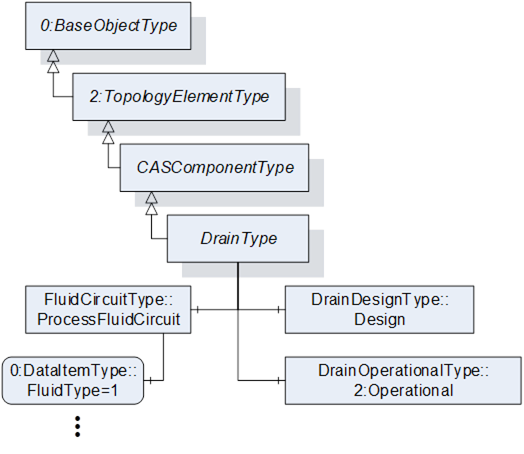
Figure 25 – DryerType Illustration
Table 31 – DrainType Definition
|
Attribute |
Value |
||||
|
BrowseName |
DrainType |
||||
|
IsAbstract |
False |
||||
|
References |
Node Class |
BrowseName |
DataType |
TypeDefinition |
Other |
|
Subtype of the CASComponentType defined in 7.7, i.e. inheriting the InstanceDeclarations of that Node. |
|||||
|
|
|
|
|
|
|
|
The following nodes override nodes added by the CASComponentType |
|||||
|
0:HasComponent |
Object |
Design |
|
DrainDesignType |
O |
|
0:HasComponent |
Object |
2:Operational |
|
DrainOperationalType |
O |
|
0:HasComponent |
Object |
ProcessFluidCircuit |
|
FluidCircuitType |
O |
When instantiating this ObjectType the Identification Object shall use one of the concrete subtypes of the MachineryItemIdentificationType, either MachineIdentificationType or MachineryComponentIdentificationType, depending on the concrete usage of this Component. The ModellingRule of the Property DeviceClass remains as mandatory and its Value Attribute shall match the value stated in Table 9.
The InstanceDeclarations of the DrainType have additional Attributes defined in Table 32.
Table 32 – DrainType Attribute values for child Nodes
|
Source Path |
Value Attribute |
Description Attribute |
||
|
|
1 |
Enumeration of possible process fluid types. |
The DryerType is the representation of a dryer and extends its supertype by specific Nodes. According to ISO 5598, a dryer reduces the moisture vapor content of the compressed air. It is illustrated in Figure 26 and formally defined in Table 33.
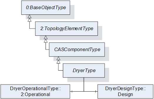
Figure 26 – DryerType Illustration
Table 33 – DryerType Definition
|
Attribute |
Value |
||||
|
BrowseName |
DryerType |
||||
|
IsAbstract |
False |
||||
|
References |
Node Class |
BrowseName |
DataType |
TypeDefinition |
Other |
|
Subtype of the CASComponentType defined in 7.7, i.e. inheriting the InstanceDeclarations of that Node. |
|||||
|
|
|
|
|
|
|
|
The following nodes override nodes added by the CASComponentType |
|||||
|
0:HasComponent |
Object |
Design |
|
DryerDesignType |
O |
|
0:HasComponent |
Object |
2:Operational |
|
DryerOperationalType |
O |
When instantiating this ObjectType the Identification Object shall use one of the concrete subtypes of the MachineryItemIdentificationType, either MachineIdentificationType or MachineryComponentIdentificationType, depending on the concrete usage of this Component. The ModellingRule of the Property DeviceClass remains as mandatory and its Value Attribute shall match the value stated in Table 9.
The FilterType is the representation of a filter and extends its supertype by specific Nodes. According to ISO 12500-1, a filter separates or removes contamination from a compressed air or gas stream. It is illustrated in Figure 27 and formally defined in Table 34.
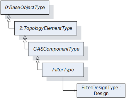
Figure 27 – FilterType Illustration
Table 34 – FilterType Definition
|
Attribute |
Value |
||||
|
BrowseName |
FilterType |
||||
|
IsAbstract |
False |
||||
|
References |
Node Class |
BrowseName |
DataType |
TypeDefinition |
Other |
|
Subtype of the CASComponentType defined in 7.7, i.e. inheriting the InstanceDeclarations of that Node. |
|||||
|
|
|
|
|
|
|
|
The following nodes are override from CASComponentType |
|||||
|
0:HasComponent |
Object |
Design |
|
FilterDesignType |
O |
When instantiating this ObjectType the Identification Object shall use one of the concrete subtypes of the MachineryItemIdentificationType, either MachineIdentificationType or MachineryComponentIdentificationType, depending on the concrete usage of this Component. The ModellingRule of the Property DeviceClass remains as mandatory and its Value Attribute shall match the value stated in Table 9.
The HeatRecoverySystemType shall be used as TypeDefinition for concrete heat recovery system Objects and shall be used as supertype for concrete heat recovery system ObjectTypes. Derived from VDMA EcoLexicon, a heat recovery system removes heat from a compressor for further utilization, such as room heating. It is formally defined in Table 35.
Table 35 – HeatRecoverySystemType Definition
|
Attribute |
Value |
||||
|
BrowseName |
HeatRecoverySystemType |
||||
|
IsAbstract |
False |
||||
|
References |
Node Class |
BrowseName |
DataType |
TypeDefinition |
Other |
|
Subtype of the CASComponentType defined in 7.7, i.e. inheriting the InstanceDeclarations of that Node. |
|||||
When instantiating this ObjectType the Identification Object shall use one of the concrete subtypes of the MachineryItemIdentificationType, either MachineIdentificationType or MachineryComponentIdentificationType, depending on the concrete usage of this Component. The ModellingRule of the Property DeviceClass remains as mandatory and its Value Attribute shall match the value stated in Table 9.
The ReceiverType is the representation of a receiver and extends its supertype by specific Nodes. According to DIN EN 13445-1, a receiver is a pressure vessel with a housing and its direct attachments up to the coupling point connecting it to other equipment, designed and built to contain fluids under pressure. It is illustrated in Figure 28 and formally defined in Table 36.
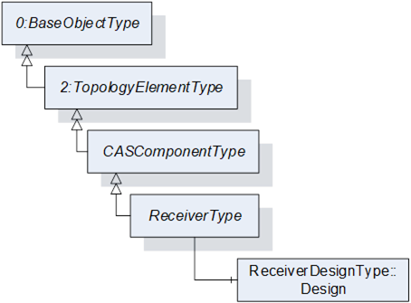
Figure 28 – ReceiverType Illustration
Table 36 – ReceiverType Definition
|
Attribute |
Value |
||||
|
BrowseName |
ReceiverType |
||||
|
IsAbstract |
False |
||||
|
References |
Node Class |
BrowseName |
DataType |
TypeDefinition |
Other |
|
Subtype of the CASComponentType defined in 7.7, i.e. inheriting the InstanceDeclarations of that Node. |
|||||
|
|
|
|
|
|
|
|
The following nodes override nodes added by the CASComponentType |
|||||
|
0:HasComponent |
Object |
Design |
|
ReceiverDesignType |
O |
When instantiating this ObjectType the Identification Object shall use one of the concrete subtypes of the MachineryItemIdentificationType, either MachineIdentificationType or MachineryComponentIdentificationType, depending on the concrete usage of this Component. The ModellingRule of the Property DeviceClass remains as mandatory and its Value Attribute shall match the value stated in Table 9.
The SensorType is the representation of a sensor and extends its supertype by specific Nodes. According to ISO 5598, a sensor is a device that detects a condition in a system or component and produces an output signal. It is illustrated in Figure 29 and formally defined in Table 37.
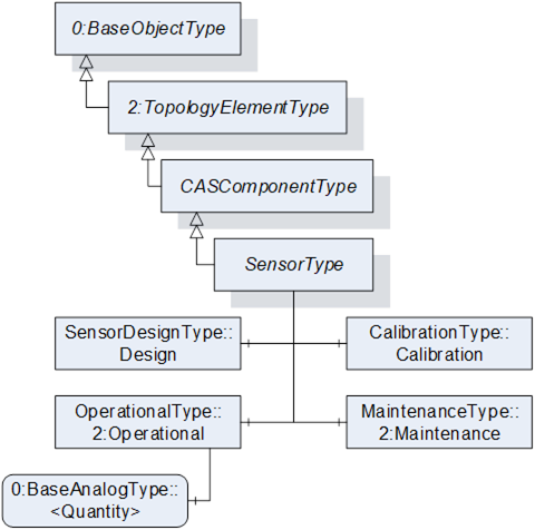
Figure 29 – SensorType Illustration
Table 37 – SensorType Definition
|
Attribute |
Value |
||||
|
BrowseName |
SensorType |
||||
|
IsAbstract |
False |
||||
|
References |
Node Class |
BrowseName |
DataType |
TypeDefinition |
Other |
|
Subtype of the CASComponentType defined in 7.7, i.e. inheriting the InstanceDeclarations of that Node. |
|||||
|
0:HasComponent |
Object |
Calibration |
|
CalibrationType |
O |
|
0:HasComponent |
Object |
2:Maintenance |
|
MaintenanceType |
O |
|
|
|
|
|
|
|
|
The following nodes override nodes added by the CASComponentType |
|||||
|
0:HasComponent |
Object |
Design |
|
SensorDesignType |
O |
|
0:HasComponent |
Object |
2:Operational |
|
OperationalType |
O |
The optional FunctionalGroup Calibration provides Variables useful for the documentation of the sensor calibration.
The optional FunctionalGroup Maintenance provides Variables useful for the documentation of the sensor maintenance.
The optional FunctionalGroup Operational is extended with an OptionalPlaceholder <Quantity> for the sensor Quantity. When instantiating a SensorType, the DataType of the <Quantity> instance must be changed to a concrete DataType. The TypeDefinition may be chosen from BaseAnalogType and its subtypes.
When instantiating this ObjectType the Identification Object shall use one of the concrete subtypes of the MachineryItemIdentificationType, either MachineIdentificationType or MachineryComponentIdentificationType, depending on the concrete usage of this Component. The ModellingRule of the Property DeviceClass remains as mandatory and its Value Attribute shall match the value stated in Table 9.
The components of the SensorType have additional subcomponents defined in Table 38.
Table 38 – SensorType Additional Subcomponents
|
Source Path |
References |
NodeClass |
BrowseName |
DataType |
TypeDefinition |
Other |
|
2:Operational |
0:HasComponent |
Variable |
<Quantity> |
0:BaseAnalogType |
OP, RO |
The InstanceDeclarations of the SensorType have additional Attributes defined in Table 39.
Table 39 – SensorType Attribute values for child Nodes
|
Source Path |
Value Attribute |
Description Attribute |
||
|
Calibration |
|
Dates important for the calibration of a sensor. |
||
|
2:Maintenance |
|
Servicing intervals for the sensor. |
||
|
|
|
Measurement or calculation performed by a sensor. |
The SeparatorType is the representation of a condensate separator and extends its supertype by specific Nodes. According to ISO 5598, a condensate separator retains contaminants by means other than a filter element, e.g. specific gravity, magnetism, chemical properties, density. It is illustrated in Figure 30 and formally defined in Table 40.
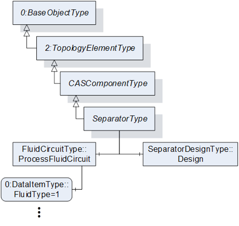
Figure 30 – SeparatorType Illustration
Table 40 – SeparatorType Definition
|
Attribute |
Value |
||||
|
BrowseName |
SeparatorType |
||||
|
IsAbstract |
False |
||||
|
References |
Node Class |
BrowseName |
DataType |
TypeDefinition |
Other |
|
Subtype of the CASComponentType defined in 7.7, i.e. inheriting the InstanceDeclarations of that Node. |
|||||
|
|
|
|
|
|
|
|
The following nodes override nodes added by the CASComponentType |
|||||
|
0:HasComponent |
Object |
Design |
|
SeparatorDesignType |
O |
|
0:HasComponent |
Object |
ProcessFluidCircuit |
|
FluidCircuitType |
O |
When instantiating this ObjectType the Identification Object shall use one of the concrete subtypes of the MachineryItemIdentificationType, either MachineIdentificationType or MachineryComponentIdentificationType, depending on the concrete usage of this Component. The ModellingRule of the Property DeviceClass remains as mandatory and its Value Attribute shall match the value stated in Table 9.
The InstanceDeclarations of the SeparatorType have additional Attributes defined in Table 41.
Table 41 – SeparatorType Attribute values for child Nodes
|
Source Path |
Value Attribute |
Description Attribute |
||
|
|
1 |
Enumeration of possible process fluid types. |
The ValveType is the representation of a valve and extends its supertype by specific Nodes. Valves control the flow and passage of fluids through a piping network. It is illustrated in Figure 31 and formally defined in Table 42.
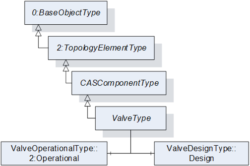
Figure 31 – ValveType Illustration
Table 42 – ValveType Definition
|
Attribute |
Value |
||||
|
BrowseName |
ValveType |
||||
|
IsAbstract |
False |
||||
|
References |
Node Class |
BrowseName |
DataType |
TypeDefinition |
Other |
|
Subtype of the CASComponentType defined in 7.7, i.e. inheriting the InstanceDeclarations of that Node. |
|||||
|
|
|
|
|
|
|
|
The following nodes override nodes added by the CASComponentType |
|||||
|
0:HasComponent |
Object |
Design |
|
ValveDesignType |
O |
|
0:HasComponent |
Object |
2:Operational |
|
ValveOperationalType |
O |
When instantiating this ObjectType the Identification Object shall use one of the concrete subtypes of the MachineryItemIdentificationType, either MachineIdentificationType or MachineryComponentIdentificationType, depending on the concrete usage of this Component. The ModellingRule of the Property DeviceClass remains as mandatory and its Value Attribute shall match the value stated in Table 9.
The ElectricalQuantitiesType provides Variables for Quantities of electrical properties and is formally defined in Table 43.
Table 43 – ElectricalQuantitiesType Definition
|
Attribute |
Value |
||||
|
BrowseName |
ElectricalQuantitiesType |
||||
|
IsAbstract |
False |
||||
|
References |
Node Class |
BrowseName |
DataType |
TypeDefinition |
Other |
|
Subtype of the 0:BaseObjectType defined in OPC 10000-5. |
|||||
|
0:HasInterface |
ObjectType |
3:IStatisticsType |
Defined in OPC 10000-200 |
||
|
|
|
|
|
|
|
|
0:HasComponent |
Variable |
ApparentPower |
0:Double |
0:BaseAnalogType |
O, RO |
|
0:HasComponent |
Variable |
Current |
0:Double |
0:BaseAnalogType |
O, RO |
|
0:HasComponent |
Variable |
Energy |
0:Double |
0:BaseAnalogType |
O, RO |
|
0:HasComponent |
Variable |
Power |
0:Double |
0:BaseAnalogType |
O, RO |
|
0:HasComponent |
Variable |
Voltage |
0:Double |
0:BaseAnalogType |
O, RO |
|
|
|
|
|
|
|
|
Applied from 3:IStatisticsType |
|||||
|
0:HasComponent |
Method |
3:ResetStatistics |
O |
||
|
0:HasProperty |
Variable |
3:StartTime |
0:DateTime |
0:PropertyType |
O, RO |
The Variable StartTime and the Method ResetStatistics are defined by the IStatisticsType and shall be used as defined by the Interface.
The InstanceDeclarations of the ElectricalQuantitiesType have additional Attributes defined in Table 44.
Table 44 – ElectricalQuantitiesType Attribute values for child Nodes
|
Source Path |
Value Attribute |
Description Attribute |
|
ApparentPower |
|
Measured or calculated actual apparent power consumption including all auxiliary components (e.g. on a compressor including fans, controller, …). |
|
Current |
|
Measured or calculated actual root mean square of the electric power consumption including all auxiliary components (e.g. on a compressor including fans, controller, …). |
|
Energy |
|
Measured or calculated accumulated electrical energy consumed including all auxiliary components (e.g. on a compressor including fans, controller, …) since last reset. |
|
Power |
|
Measured or calculated actual electric real power consumption including all auxiliary components (e.g. on a compressor including fans, controller, …). |
|
Voltage |
|
Measured or calculated actual root mean square of the voltage applied including all auxiliary components (e.g. on a compressor including fans, controller, …). |
The ElectricalCircuitType provides Objects that are used to group common Quantities of electrical properties and is formally defined in Table 51.
Table 45 – ElectricalCircuitType Definition
|
Attribute |
Value |
||||
|
BrowseName |
ElectricalCircuitType |
||||
|
IsAbstract |
False |
||||
|
References |
Node Class |
BrowseName |
DataType |
TypeDefinition |
Other |
|
Subtype of the 0:BaseObjectType defined in OPC 10000-5. |
|||||
|
0:HasComponent |
Object |
<Other> |
|
ElectricalQuantitiesType |
OP |
|
0:HasComponent |
Object |
Delta |
|
ElectricalQuantitiesType |
O |
|
0:HasComponent |
Object |
Input |
|
ElectricalQuantitiesType |
O |
|
0:HasComponent |
Object |
Output |
|
ElectricalQuantitiesType |
O |
The OptionalPlaceholder <Other> is used to add manufacturer or system specific groups to an electrical circuit.
The InstanceDeclarations of the ElectricalCircuitType have additional Attributes defined in Table 46.
Table 46 – ElectricalCircuitType Attribute values for child Nodes
|
Source Path |
Description Attribute |
|
<Other> |
Placeholder for manufacturer or system specific groups. |
|
Delta |
Measured or calculated deltas of electrical properties between inlet and outlet of the component. |
|
Input |
Measured or calculated electrical properties at the input of the component. |
|
Output |
Measured or calculated electrical properties at the output of the component. |
The FluidQuantitiesType provides Variables and Objects for fluid Quantities and is formally defined in Table 47.
Table 47 – FluidQuantitiesType Definition
|
Attribute |
Value |
||||
|
BrowseName |
FluidQuantitiesType |
||||
|
IsAbstract |
False |
||||
|
References |
Node Class |
BrowseName |
DataType |
TypeDefinition |
Other |
|
Subtype of the 0:BaseObjectType defined in OPC 10000-5. |
|||||
|
0:HasInterface |
ObjectType |
3:IStatisticsType |
Defined in OPC 10000-200 |
||
|
|
|
|
|
|
|
|
0:HasComponent |
Variable |
<Quantity> |
0:BaseAnalogType |
OP, RO |
|
|
0:HasComponent |
Variable |
AbsolutePressure |
0:Double |
0:BaseAnalogType |
O, RO |
|
0:HasComponent |
Variable |
AccumulatedVolume |
0:Double |
0:BaseAnalogType |
O, RO |
|
0:HasComponent |
Variable |
DewPoint |
0:Double |
0:BaseAnalogType |
O, RO |
|
0:HasComponent |
Variable |
GaugePressure |
0:Double |
0:BaseAnalogType |
O, RO |
|
0:HasComponent |
Variable |
MassFlowRate |
0:Double |
0:BaseAnalogType |
O, RO |
|
0:HasComponent |
Variable |
OilConcentration |
0:Double |
0:BaseAnalogType |
O, RO |
|
0:HasComponent |
Object |
ParticlesPerSizeRange |
|
ParticleType |
O |
|
0:HasComponent |
Variable |
RelativeHumidity |
0:Double |
0:BaseAnalogType |
O, RO |
|
0:HasComponent |
Variable |
Temperature |
0:Double |
0:BaseAnalogType |
O, RO |
|
0:HasComponent |
Variable |
Volume |
0:Double |
0:BaseAnalogType |
O, RO |
|
0:HasComponent |
Variable |
VolumeFlowRate |
0:Double |
0:BaseAnalogType |
O, RO |
|
|
|
|
|
|
|
|
Applied from 3:IStatisticsType |
|||||
|
0:HasComponent |
Method |
3:ResetStatistics |
O |
||
|
0:HasProperty |
Variable |
3:StartTime |
0:DateTime |
0:PropertyType |
O, RO |
The Variable StartTime and the Method ResetStatistics are defined by the IStatisticsType and shall be used as defined by the Interface.
The OptionalPlaceholder <Quantity> is used to add additional Quantities to this group. In this case the abstract DataType 0:Number must be changed to a non-abstract DataType. The TypeDefinition may be chosen from BaseAnalogType and its subtypes.
The InstanceDeclarations of the FluidQuantitiesType have additional Attributes defined in Table 48.
Table 48 – FluidQuantitiesType Attribute values for child Nodes
|
Source Path |
Value Attribute |
Description Attribute |
|
<Quantity> |
|
Manufacturer or system specific measurements or calculations. |
|
AbsolutePressure |
|
Measured or calculated actual absolute pressure of a fluid. |
|
AccumulatedVolume |
|
Measured or calculated accumulated volume of a fluid since last reset. |
|
DewPoint |
|
Measured or calculated actual dew point of a fluid. |
|
GaugePressure |
|
Measured or calculated actual gauge pressure of a fluid. |
|
MassFlowRate |
|
Measured or calculated actual mass flow rate of a fluid. |
|
OilConcentration |
|
Measured or calculated actual oil concentration of a fluid. |
|
ParticlesPerSizeRange |
|
Collection of particle counts for a fluid according to ISO 8573. |
|
RelativeHumidity |
|
Measured or calculated actual relative humidity of a fluid. |
|
Temperature |
|
Measured or calculated actual temperature of a fluid. |
|
Volume |
|
Measured or calculated actual volume of a fluid. |
|
VolumeFlowRate |
|
Measured or calculated actual volume flow rate of a fluid. |
The ParticleType provides Variables for particle counting in a fluid in three categories according to ISO 8573-1:2010-04 Compressed air – Part 1: Contaminants and purity classes. It is formally defined in Table 49.
Table 49 – ParticleType Definition
|
Attribute |
Value |
||||
|
BrowseName |
ParticleType |
||||
|
IsAbstract |
False |
||||
|
References |
Node Class |
BrowseName |
DataType |
TypeDefinition |
Other |
|
Subtype of the 0:BaseObjectType defined in OPC 10000-5. |
|||||
|
0:HasComponent |
Variable |
Fine |
0:UInt64 |
0:BaseAnalogType |
M, RO |
|
0:HasComponent |
Variable |
Large |
0:UInt64 |
0:BaseAnalogType |
M, RO |
|
0:HasComponent |
Variable |
Medium |
0:UInt64 |
0:BaseAnalogType |
M, RO |
The InstanceDeclarations of the ParticleType have additional Attributes defined in Table 50.
Table 50 – ParticleType Attribute values for child Nodes
|
Source Path |
Value Attribute |
Description Attribute |
|
Fine |
|
Particle count of sizes from 0.1 to 0.5 um. |
|
Large |
|
Particle count of sizes from 1.0 to 5.0 um. |
|
Medium |
|
Particle count of sizes from 0.5 to 1.0 um. |
The FluidCircuitType provides Objects that are used to group fluid Quantities and is formally defined in Table 51.
Table 51 – FluidCircuitType Definition
|
Attribute |
Value |
||||
|
BrowseName |
FluidCircuitType |
||||
|
IsAbstract |
False |
||||
|
References |
Node Class |
BrowseName |
DataType |
TypeDefinition |
Other |
|
Subtype of the 0:BaseObjectType defined in OPC 10000-5. |
|||||
|
0:HasComponent |
Object |
<Other> |
|
FluidQuantitiesType |
OP |
|
0:HasComponent |
Object |
Delta |
|
FluidQuantitiesType |
O |
|
0:HasComponent |
Variable |
FluidType |
FluidTypeEnum |
0:DataItemType |
O, RO |
|
0:HasComponent |
Object |
Inlet |
|
FluidQuantitiesType |
O |
|
0:HasComponent |
Object |
Outlet |
|
FluidQuantitiesType |
O |
The OptionalPlaceholder Object <Other> is used to add manufacturer or system specific groups to a fluid circuit.
The InstanceDeclarations of the FluidCircuitType have additional Attributes defined in Table 52.
Table 52 – FluidCircuitType Attribute values for child Nodes
|
Source Path |
Description Attribute |
|
<Other> |
Placeholder for manufacturer or system specific groups. |
|
Delta |
Measured or calculated deltas of fluid properties between inlet and outlet of the component. |
|
FluidType |
Enumeration of possible fluid types. |
|
Inlet |
Measured or calculated fluid properties at the inlet of the component. |
|
Outlet |
Measured or calculated fluid properties at the outlet of the component. |
The AnalysisType provides Objects and Methods that are used for invoking an analysis on the Main Control System and is formally defined in Table 53.
Table 53 – AnalysisType Definition
|
Attribute |
Value |
||||
|
BrowseName |
AnalysisType |
||||
|
IsAbstract |
False |
||||
|
References |
Node Class |
BrowseName |
DataType |
TypeDefinition |
Other |
|
Subtype of the 0:BaseObjectType defined in OPC 10000-5. |
|||||
|
0:HasComponent |
Object |
OutputFile |
|
0:FileType |
O |
|
0:HasComponent |
Method |
Trigger |
See 7.25.1 |
O |
|
The optional Object OutputFile shall contain the result of an analysis if the Main Control System can provide a file in the AddressSpace of the OPC UA Server. If not, this Object must not be instantiated.
The results of an analysis may be submitted to the user via any communication technology. It is not necessary to provide the result in the OPC UA AddressSpace. However, it is recommended to do so if the Server is capable of such an operation. An analysis output file may be any kind of file. The manufacturer shall define the provided file type and any other necessary information.
The optional Method Trigger is used to invoke the generation of an analysis report on the Main Control System.
To define a parameterizable analysis, the manufacturer or integrator shall define a subtype of this AnalysisType. The Method Trigger shall be overridden, and the required parameters shall be added as InputArguments. The manufacturer or integrator may add Variables or Properties to the new subtype to represent the parameters.
The InstanceDeclarations of the AnalysisType have additional Attributes defined in Table 54.
Table 54 – AnalysisType Attribute values for child Nodes
|
Source Path |
Description Attribute |
|
OutputFile |
File containing the result of an analysis. |
|
Trigger |
Triggers the analysis on the MCS in a compressed air system. |
The Method Trigger is used to trigger an analysis on the Main Control System. The signature of this Method is specified below. There are no InputArguments or OutputArguments defined. Its formal representation in the AddressSpace is defined in Table 55.
Signature
Trigger (
);
Table 55 – Trigger Method AddressSpace Definition
|
Attribute |
Value |
||||
|
BrowseName |
Trigger |
||||
|
References |
Node Class |
BrowseName |
DataType |
TypeDefinition |
ModellingRule |
|
|
|
|
|
|
|
The AnalysesType provides Objects for invoking analyses performed by the Main Control System and is formally defined in Table 56. Such analyses may be performed on Compressed Air System or Airnet level.
Table 56 – AnalysesType Definition
|
Attribute |
Value |
||||
|
BrowseName |
AnalysesType |
||||
|
IsAbstract |
False |
||||
|
References |
Node Class |
BrowseName |
DataType |
TypeDefinition |
Other |
|
Subtype of the 2:FunctionalGroupType defined in OPC 10000-100, i.e. inheriting the InstanceDeclarations of that Node. |
|||||
|
0:HasComponent |
Object |
<Analysis> |
|
AnalysisType |
OP |
|
0:HasComponent |
Object |
<PrefabAnalysis> |
|
0:FileType |
OP |
|
0:HasComponent |
Object |
EnergyReportISO50001 |
|
AnalysisType |
O |
The OptionalPlaceholder Object <PrefabAnalyses> can be used to provide results of analyses performed by the manufacturer, automatically recurring analyses performed by the Main Control System, or other analyses that do not require a trigger and an output file.
The optional Object EnergyReportISO50001 can be used as a pre-parameterized analysis for generating an energy report according to ISO 50001. The parameterization for this analysis should be provided on the Main Control System.
The InstanceDeclarations of the AnalysesType have additional Attributes defined in Table 57.
Table 57 – AnalysesType Attribute values for child Nodes
|
Source Path |
Description Attribute |
|
<Analysis> |
Manufacturer or system specific analyses. |
|
<PrefabAnalysis> |
Prefabricated analysis provided by the MCS. |
|
EnergyReportISO50001 |
Energy report according to ISO 50001. |
The CalibrationType provides Variables useful for the calibration of a sensor and is formally defined in Table 58.
Table 58 – CalibrationType Definition
|
Attribute |
Value |
||||
|
BrowseName |
CalibrationType |
||||
|
IsAbstract |
False |
||||
|
References |
Node Class |
BrowseName |
DataType |
TypeDefinition |
Other |
|
Subtype of the 2:FunctionalGroupType defined in OPC 10000-100, i.e. inheriting the InstanceDeclarations of that Node |
|||||
|
0:HasComponent |
Variable |
LastCalibrationDate |
0:DateTime |
0:DataItemType |
M, RO |
|
0:HasComponent |
Variable |
NextCalibrationDate |
0:DateTime |
0:DataItemType |
M, RO |
The InstanceDeclarations of the CalibrationType have additional Attributes defined in Table 59.
Table 59 – CalibrationType Attribute values for child Nodes
|
Source Path |
Description Attribute |
|
LastCalibrationDate |
Date when the sensor was last calibrated. |
|
NextCalibrationDate |
Date when the sensor is scheduled for the next calibration. |
The CASIdentificationType provides Properties for basic identification purposes for Compressed Air Systems and Airnets. It is formally defined in Table 60.
Table 60 – CASIdentificationType Definition
|
Attribute |
Value |
||||
|
BrowseName |
CASIdentificationType |
||||
|
IsAbstract |
False |
||||
|
References |
Node Class |
BrowseName |
DataType |
TypeDefinition |
Other |
|
Subtype of the 2:FunctionalGroupType defined in OPC 10000-100, i.e. inheriting the InstanceDeclarations of that Node |
|||||
|
0:HasInterface |
ObjectType |
2:ITagNameplateType |
Defined in OPC 10000-100 |
||
|
|
|
|
|
|
|
|
Applied from 2:ITagNameplateType |
|||||
|
0:HasProperty |
Variable |
2:AssetId |
0:String |
0:PropertyType |
O, RW |
|
0:HasProperty |
Variable |
2:ComponentName |
0:LocalizedText |
0:PropertyType |
O, RW |
The Properties AssetId and ComponentName are defined by the ITagNameplateType and shall be used as defined by the Interface.
The ConfigurationType provides a framework for Nodes aimed at configuring the behavior of a CASPart. This specification defines configuration properties for Airnets and the Main Control System. There are no configuration properties defined for Components. It is formally defined in Table 61.
Table 61 – ConfigurationType Definition
|
Attribute |
Value |
||||
|
BrowseName |
ConfigurationType |
||||
|
IsAbstract |
False |
||||
|
References |
Node Class |
BrowseName |
DataType |
TypeDefinition |
Other |
|
Subtype of the 2:FunctionalGroupType defined in OPC 10000-100, i.e. inheriting the InstanceDeclarations of that Node. |
|||||
|
0:HasSubtype |
ObjectType |
AirnetConfigurationType |
Defined in 7.30 |
||
|
0:HasSubtype |
ObjectType |
MCSConfigurationType |
Defined in 7.31 |
||
The AirnetConfigurationType provides Variables for configuring the behavior of an Airnet and is formally defined in Table 62.
Table 62 – AirnetConfigurationType Definition
|
Attribute |
Value |
||||
|
BrowseName |
AirnetConfigurationType |
||||
|
IsAbstract |
False |
||||
|
References |
Node Class |
BrowseName |
DataType |
TypeDefinition |
Other |
|
Subtype of the ConfigurationType defined in 7.28, i.e. inheriting the InstanceDeclarations of that Node. |
|||||
|
0:HasComponent |
Variable |
OperatingModes |
0:UInt16 |
0:MultiStateDiscreteType |
O, RW |
|
0:HasComponent |
Variable |
OperatingProfiles |
0:UInt16 |
0:MultiStateDiscreteType |
M, RW |
The optional Variable OperatingModes provides manufacturer or system specific operating modes of an Airnet. When instantiating the AirnetConfigurationType, the manufacturer or system integrator shall add specific operating modes to the EnumStrings Property. However, Value 0 is already predefined as stopped operating mode. Examples for other operating modes are energy or maintenance optimized operating modes which are not specified by this specification.
The mandatory Variable OperatingProfiles provides manufacturer or system specific operating profiles of an Airnet. On the Main Control System, operating profiles are stored as sets of parameters for parameterizing the behavior of an Airnet. When instantiating the AirnetConfigurationType, the manufacturer or system integrator shall add specific operating profiles to the EnumStrings Property. An operating profile may change the OperatingMode Variable. An example for such profiles is the weekday profile, which change the operating mode and/or other parameters depending on the weekday.
The InstanceDeclarations of the AirnetConfigurationType have additional Attributes defined in Table 63.
Table 63 – AirnetConfigurationType Attribute values for child Nodes
|
Source Path |
Value Attribute |
Description Attribute |
||
|
OperatingModes |
|
Configured operating mode for an airnet in a compressed air system. |
||
|
|
stopped |
Available operating modes for an airnet in a compressed air system. |
||
|
OperatingProfiles |
|
Configured operating profile for an airnet in a compressed air system. |
||
|
|
|
Available operating profiles for an airnet in a compressed air system. |
The MCSConfigurationType provides Objects and Methods for configuring the behavior of the Compressed Air System and is formally defined in Table 64.
Table 64 – MCSConfigurationType Definition
|
Attribute |
Value |
||||
|
BrowseName |
MCSConfigurationType |
||||
|
IsAbstract |
False |
||||
|
References |
Node Class |
BrowseName |
DataType |
TypeDefinition |
Other |
|
Subtype of the ConfigurationType defined in 7.28, i.e. inheriting the InstanceDeclarations of that Node. |
|||||
|
0:HasComponent |
Object |
CommunicationSettings |
|
CommunicationSettingsType |
O |
|
0:HasComponent |
Object |
ConfigurationFile |
|
0:FileType |
O |
|
0:HasComponent |
Method |
LoadConfigurationFile |
See 7.31.1 |
O |
|
|
0:HasComponent |
Method |
SaveConfigurationFile |
See 7.31.2 |
O |
|
The optional Object CommunicationSettings is used to display the ethernet communication settings of the OPC UA connection point of the Main Control System.
The optional Object ConfigurationFile of the FileType shall be used to store the Main Control System configuration in the OPC UA AddressSpace. This configuration file may be uploaded to or downloaded from the Main Control System using the described Methods. It should be a persistent representation of the currently active configuration for the Compressed Air System.
The optional Method LoadConfigurationFile is the trigger for uploading the configuration stored in the ConfigurationFile Object to the Main Control System.
The optional Method SaveConfigurationFile is the trigger for downloading the current configuration from the Main Control System and store it in the ConfigurationFile Object.
The InstanceDeclarations of the MCSConfigurationType have additional Attributes defined in Table 65.
Table 65 – MCSConfigurationType Attribute values for child Nodes
|
Source Path |
Description Attribute |
|
CommunicationSettings |
OPC UA communication settings of the MCS in a compressed air system. |
|
ConfigurationFile |
Configuration file for the MCS in a compressed air system. |
|
LoadConfigurationFile |
Loads the configuration stored in ConfigurationFile to the MCS. |
|
SaveConfigurationFile |
Saves the current configuration of the MCS to the stored ConfigurationFile. |
The Method LoadConfigurationFile is used to load the configuration file stored in ConfigurationFile into the Main Control System. The signature of this Method is specified below. There are no InputArguments or OutputArguments defined. Its formal representation in the AddressSpace is defined in Table 66.
Signature
LoadConfigurationFile (
);
Table 66 – LoadConfigurationFile Method AddressSpace Definition
|
Attribute |
Value |
||||
|
BrowseName |
LoadConfigurationFile |
||||
|
References |
Node Class |
BrowseName |
DataType |
TypeDefinition |
ModellingRule |
|
|
|
|
|
|
|
The Method SaveConfigurationFile is used to save the current configuration of the Main Control System to the file stored in ConfigurationFile. The signature of this Method is specified below. There are no InputArguments or OutputArguments defined. Its formal representation in the AddressSpace is defined in Table 67.
Signature
SaveConfigurationFile (
);
Table 67 – SaveConfigurationFile Method AddressSpace Definition
|
Attribute |
Value |
||||
|
BrowseName |
SaveConfigurationFile |
||||
|
References |
Node Class |
BrowseName |
DataType |
TypeDefinition |
ModellingRule |
|
|
|
|
|
|
|
The CommunicationSettingsType provides Variables for the communication settings of the Main Control System and is formally defined in Table 68.
Table 68 – CommunicationSettingsType Definition
|
Attribute |
Value |
||||
|
BrowseName |
CommunicationSettingsType |
||||
|
IsAbstract |
False |
||||
|
References |
Node Class |
BrowseName |
DataType |
TypeDefinition |
Other |
|
Subtype of the 0:BaseObjectType defined in OPC 10000-5. |
|||||
|
0:HasProperty |
Variable |
DefaultGateway |
0:String |
0:PropertyType |
O, RO |
|
0:HasComponent |
Variable |
Dhcp |
0:Boolean |
0:TwoStateDiscreteType |
O, RO |
|
0:HasProperty |
Variable |
DnsServer |
0:String |
0:PropertyType |
O, RO |
|
0:HasProperty |
Variable |
DomainName |
0:String |
0:PropertyType |
O, RO |
|
0:HasProperty |
Variable |
Hostname |
0:String |
0:PropertyType |
O, RO |
|
0:HasProperty |
Variable |
IpAddress |
0:String |
0:PropertyType |
M, RO |
|
0:HasProperty |
Variable |
IpVersion |
IpVersionEnum |
0:PropertyType |
O, RO |
|
0:HasComponent |
Variable |
MacAddress |
0:String |
0:BaseDataVariableType |
O, RO |
|
0:HasProperty |
Variable |
SubnetMask |
0:String |
0:PropertyType |
O, RO |
The InstanceDeclarations of the CommunicationSettingsType have additional Attributes defined in Table 69.
Table 69 – CommunicationSettingsType Attribute values for child Nodes
|
Source Path |
Value Attribute |
Description Attribute |
||
|
DefaultGateway |
|
IP Address of the default gateway used by the MCS. |
||
|
Dhcp |
|
States if DHCP is enabled or disabled on the MCS. |
||
|
|
“DHCP disabled” |
|
||
|
|
“DHCP enabled” |
|
||
|
DnsServer |
|
IP Address of the DNS server used by the MCS. |
||
|
DomainName |
|
Domain name the MCS is assigned to. |
||
|
Hostname |
|
Host name of the MCS. |
||
|
IpAddress |
|
IP address of the MCS. |
||
|
IpVersion |
|
Version of the internet protocol used for the MCS. |
||
|
MacAddress |
|
MAC address of the NIC of the MCS. |
||
|
SubnetMask |
|
Subnet mask of the MCS. |
The DesignType provides a framework and Variables for static design information of Components and is formally defined in Table 70.
Table 70 – DesignType Definition
|
Attribute |
Value |
||||
|
BrowseName |
DesignType |
||||
|
IsAbstract |
False |
||||
|
References |
Node Class |
BrowseName |
DataType |
TypeDefinition |
Other |
|
Subtype of the 2:FunctionalGroupType defined in OPC 10000-100, i.e. inheriting the InstanceDeclarations of that Node |
|||||
|
0:HasSubtype |
ObjectType |
CompressorDesignType |
Defined in 7.34 |
||
|
0:HasSubtype |
ObjectType |
ConverterDesignType |
Defined in 7.35 |
||
|
0:HasSubtype |
ObjectType |
DrainDesignType |
Defined in 7.36 |
||
|
0:HasSubtype |
ObjectType |
DryerDesignType |
Defined in 7.37 |
||
|
0:HasSubtype |
ObjectType |
FilterDesignType |
Defined in 7.38 |
||
|
0:HasSubtype |
ObjectType |
ReceiverDesignType |
Defined in 7.39 |
||
|
0:HasSubtype |
ObjectType |
SensorDesignType |
Defined in 7.40 |
||
|
0:HasSubtype |
ObjectType |
SeparatorDesignType |
Defined in 7.41 |
||
|
0:HasSubtype |
ObjectType |
ValveDesignType |
Defined in 7.42 |
||
|
|
|
|
|
|
|
|
0:HasComponent |
Variable |
ComponentClass |
0:DataItemType |
O, RO |
|
The InstanceDeclarations of the DesignType have additional Attributes defined in Table 71.
Table 71 – DesignType Attribute values for child Nodes
|
Source Path |
Description Attribute |
|
ComponentClass |
Enumeration of possible types of the component’s device class. |
The CompressorDesignType extends its supertype by compressor specific Variables and is formally defined in Table 72.
Table 72 – CompressorDesignType Definition
|
Attribute |
Value |
||||
|
BrowseName |
CompressorDesignType |
||||
|
IsAbstract |
False |
||||
|
References |
Node Class |
BrowseName |
DataType |
TypeDefinition |
Other |
|
Subtype of the DesignType defined in 7.33, i.e. inheriting the InstanceDeclarations of that Node |
|||||
|
0:HasComponent |
Variable |
DisplacementType |
DisplacementTypeEnum |
0:DataItemType |
O, RO |
|
0:HasComponent |
Variable |
LubricationType |
LubricationTypeEnum |
0:DataItemType |
O, RO |
|
0:HasComponent |
Variable |
NumberOfStages |
0:UInt16 |
0:DataItemType |
O, RO |
|
0:HasComponent |
Variable |
VariableFlow |
0:Boolean |
0:TwoStateDiscreteType |
O, RO |
|
|
|
|
|
|
|
|
The following nodes override properties and components of the DesignType |
|||||
|
0:HasComponent |
Variable |
ComponentClass |
CompressorTypeEnum |
0:DataItemType |
O, RO |
The InstanceDeclarations of the CompressorDesignType have additional Attributes defined in Table 73.
Table 73 – CompressorDesignType Attribute values for child Nodes
|
Source Path |
Value Attribute |
Description Attribute |
||
|
ComponentClass |
|
Enumeration of possible compressor types. |
||
|
DisplacementType |
|
Enumeration of possible displacement types. |
||
|
LubricationType |
|
Enumeration of possible lubrication types for the compression process of a compressor. |
||
|
NumberOfStages |
|
Number of stages the compressor has available. |
||
|
VariableFlow |
|
Indicates if a compressor has a variable or fixed flow. |
||
|
|
'Fixed flow' means the product offers no control for changing the volume flow independent of pressure. |
|
||
|
|
'Variable flow' means the compressor package allows an intentional change in volume flow rate, most obviously by VSD but also by adjustable guide vanes in turbo compressors or by valve controls in piston compressors or other means. |
|
The ConverterDesignType extends its supertype by converter specific Variables and is formally defined in Table 74.
Table 74 – ConverterDesignType Definition
|
Attribute |
Value |
||||
|
BrowseName |
ConverterDesignType |
||||
|
IsAbstract |
False |
||||
|
References |
Node Class |
BrowseName |
DataType |
TypeDefinition |
Other |
|
Subtype of the DesignType defined in 7.33, i.e. inheriting the InstanceDeclarations of that Node |
|||||
|
|
|
|
|
|
|
|
The following nodes override properties and components of the DesignType |
|||||
|
0:HasComponent |
Variable |
ComponentClass |
ConverterTypeEnum |
0:DataItemType |
O, RO |
The InstanceDeclarations of the ConverterDesignType have additional Attributes defined in Table 75.
Table 75 – ConverterDesignType Attribute values for child Nodes
|
Source Path |
Description Attribute |
|
ComponentClass |
Enumeration of possible converter types. |
The DrainDesignType extends its supertype by condensate drain specific Variables and is formally defined in Table 76.
Table 76 – DrainDesignType Definition
|
Attribute |
Value |
||||
|
BrowseName |
DrainDesignType |
||||
|
IsAbstract |
False |
||||
|
References |
Node Class |
BrowseName |
DataType |
TypeDefinition |
Other |
|
Subtype of the DesignType defined in 7.33, i.e. inheriting the InstanceDeclarations of that Node |
|||||
|
|
|
|
|
|
|
|
The following nodes override properties and components of the DesignType |
|||||
|
0:HasComponent |
Variable |
ComponentClass |
DrainTypeEnum |
0:DataItemType |
O, RO |
The InstanceDeclarations of the DrainDesignType have additional Attributes defined in Table 77.
Table 77 – DrainDesignType Attribute values for child Nodes
|
Source Path |
Description Attribute |
|
ComponentClass |
Enumeration of possible condensate drain types. |
The DryerDesignType extends its supertype by dryer specific Variables and is formally defined in Table 78.
Table 78 – DryerDesignType Definition
|
Attribute |
Value |
||||
|
BrowseName |
DryerDesignType |
||||
|
IsAbstract |
False |
||||
|
References |
Node Class |
BrowseName |
DataType |
TypeDefinition |
Other |
|
Subtype of the DesignType defined in 7.33, i.e. inheriting the InstanceDeclarations of that Node |
|||||
|
0:HasComponent |
Variable |
LowestAmbientTemperature |
0:Double |
0:BaseAnalogType |
O, RO |
|
|
|
|
|
|
|
|
The following nodes override properties and components of the DesignType |
|||||
|
0:HasComponent |
Variable |
ComponentClass |
DryerTypeEnum |
0:DataItemType |
O, RO |
The InstanceDeclarations of the DryerDesignType have additional Attributes defined in Table 79.
Table 79 – DryerDesignType Attribute values for child Nodes
|
Source Path |
Description Attribute |
|
ComponentClass |
Enumeration of possible dryer types. |
|
LowestAmbientTemperature |
Lowest allowable ambient temperature for the dryer to work as intended. |
The FilterDesignType extends its supertype by filter specific Variables and is formally defined in Table 80.
Table 80 – FilterDesignType Definition
|
Attribute |
Value |
||||
|
BrowseName |
FilterDesignType |
||||
|
IsAbstract |
False |
||||
|
References |
Node Class |
BrowseName |
DataType |
TypeDefinition |
Other |
|
Subtype of the DesignType defined in 7.33, i.e. inheriting the InstanceDeclarations of that Node |
|||||
|
0:HasComponent |
Variable |
FilterClass |
FilterClassDataType |
0:DataItemType |
O, RO |
|
|
|
|
|
|
|
|
The following nodes override properties and components of the DesignType |
|||||
|
0:HasComponent |
Variable |
ComponentClass |
FilterTypeEnum |
0:DataItemType |
O, RO |
The InstanceDeclarations of the FilterDesignType have additional Attributes defined in Table 81.
Table 81 – FilterDesignType Attribute values for child Nodes
|
Source Path |
Description Attribute |
|
ComponentClass |
Enumeration of possible filter types. |
|
FilterClass |
Filter classes according to ISO 8573-1. |
The ReceiverDesignType extends its supertype by receiver specific Variables and is formally defined in Table 82.
Table 82 – ReceiverDesignType Definition
|
Attribute |
Value |
||||
|
BrowseName |
ReceiverDesignType |
||||
|
IsAbstract |
False |
||||
|
References |
Node Class |
BrowseName |
DataType |
TypeDefinition |
Other |
|
Subtype of the DesignType defined in 7.33, i.e. inheriting the InstanceDeclarations of that Node |
|||||
|
|
|
|
|
|
|
|
The following nodes override properties and components of the DesignType |
|||||
|
0:HasComponent |
Variable |
ComponentClass |
ReceiverTypeEnum |
0:DataItemType |
O, RO |
|
0:HasComponent |
Variable |
Volume |
0:Double |
0:AnalogUnitType |
O, RO |
The InstanceDeclarations of the ReceiverDesignType have additional Attributes defined in Table 83.
Table 83 – ReceiverDesignType Attribute values for child Nodes
|
Source Path |
Description Attribute |
|
ComponentClass |
Enumeration of possible receiver types. |
|
Volume |
Total volume of the receiver. |
The SensorDesignType extends its supertype by sensor specific Variables and is formally defined in Table 84.
Table 84 – SensorDesignType Definition
|
Attribute |
Value |
||||
|
BrowseName |
SensorDesignType |
||||
|
IsAbstract |
False |
||||
|
References |
Node Class |
BrowseName |
DataType |
TypeDefinition |
Other |
|
Subtype of the DesignType defined in 7.33, i.e. inheriting the InstanceDeclarations of that Node |
|||||
|
0:HasComponent |
Variable |
SensorTechnology |
SensorTechnologyOptionSet |
0:DataItemType |
O, RO |
|
0:HasComponent |
Variable |
SoftSensor |
0:Boolean |
0:TwoStateDiscreteType |
O, RO |
|
|
|
|
|
|
|
|
The following nodes override properties and components of the DesignType |
|||||
|
0:HasComponent |
Variable |
ComponentClass |
SensorTypeEnum |
0:DataItemType |
O, RO |
The InstanceDeclarations of the SensorDesignType have additional Attributes defined in Table 85.
Table 85 – SensorDesignType Attribute values for child Nodes
|
Source Path |
Value Attribute |
Description Attribute |
||
|
ComponentClass |
|
Enumeration of possible sensor types. |
||
|
SensorTechnology |
|
Selection of sensor technologies this sensor uses. |
||
|
SoftSensor |
|
Indicates if the sensor is a software or hardware sensor. |
||
|
|
“This sensor is a hardware sensor.” |
|
||
|
|
“This sensor is a software sensor.” |
|
The SeparatorDesignType extends its supertype by condensate separator specific Variables and is formally defined in Table 86.
Table 86 – SeparatorDesignType Definition
|
Attribute |
Value |
||||
|
BrowseName |
SeparatorDesignType |
||||
|
IsAbstract |
False |
||||
|
References |
Node Class |
BrowseName |
DataType |
TypeDefinition |
Other |
|
Subtype of the DesignType defined in 7.33, i.e. inheriting the InstanceDeclarations of that Node |
|||||
|
|
|
|
|
|
|
|
The following nodes override properties and components of the DesignType |
|||||
|
0:HasComponent |
Variable |
ComponentClass |
SeparatorTypeEnum |
0:DataItemType |
O, RO |
The InstanceDeclarations of the SeparatorDesignType have additional Attributes defined in Table 87.
Table 87 – SeparatorDesignType Attribute values for child Nodes
|
Source Path |
Description Attribute |
|
ComponentClass |
Enumeration of possible condensate separator types. |
The ValveDesignType extends its supertype by valve specific Variables and is formally defined in Table 88.
Table 88 – ValveDesignType Definition
|
Attribute |
Value |
||||
|
BrowseName |
ValveDesignType |
||||
|
IsAbstract |
False |
||||
|
References |
Node Class |
BrowseName |
DataType |
TypeDefinition |
Other |
|
Subtype of the DesignType defined in 7.33, i.e. inheriting the InstanceDeclarations of that Node |
|||||
|
0:HasComponent |
Variable |
NumberOfPorts |
0:UInt16 |
0:DataItemType |
O, RO |
|
|
|
|
|
|
|
|
The following nodes override properties and components of the DesignType |
|||||
|
0:HasComponent |
Variable |
ComponentClass |
ValveTypeEnum |
0:DataItemType |
O, RO |
The InstanceDeclarations of the ValveDesignType have additional Attributes defined in Table 89.
Table 89 – ValveDesignType Attribute values for child Nodes
|
Source Path |
Description Attribute |
|
ComponentClass |
Enumeration of possible valve types. |
|
NumberOfPorts |
Number of ports of a valve. |
The EventsType provides Objects for conditions of Components and is formally defined in Table 90.
Table 90 – EventsType Definition
|
Attribute |
Value |
||||
|
BrowseName |
EventsType |
||||
|
IsAbstract |
False |
||||
|
References |
Node Class |
BrowseName |
DataType |
TypeDefinition |
Other |
|
Subtype of the 2:FunctionalGroupType defined in OPC 10000-100, i.e. inheriting the InstanceDeclarations of that Node. |
|||||
|
0:HasComponent |
Object |
<Event> |
|
OP |
|
|
0:HasComponent |
Object |
EmergencyStop |
|
0:OffNormalAlarmType |
O |
|
0:HasComponent |
Object |
Service |
|
0:OffNormalAlarmType |
O |
|
0:HasComponent |
Object |
Shutdown |
|
0:OffNormalAlarmType |
O |
|
0:HasComponent |
Object |
Warning |
|
0:OffNormalAlarmType |
O |
The OptionalPlaceholder Object <Event> is used to add additional conditions to an instance of the EventsType. In this case a concrete subtype of the abstract ConditionType has to be used as TypeDefinition.
The InstanceDeclarations of the EventsType have additional Attributes defined in Table 91.
Table 91 – EventsType Attribute values for child Nodes
|
Source Path |
Description Attribute |
|
<Event> |
Manufacturer or system specific conditions. |
|
EmergencyStop |
Indicating an emergency stop of a component. |
|
Service |
Indicates that a component requires service. |
|
Shutdown |
Indicating a shutdown of a component. |
|
Warning |
Indicating a general warning of a component. |
When instantiating this EventsType, specific severities shall be assigned to each event or condition. The severity ranges as well as the states for each InstanceDeclaration of the EventsType are defined in Table 92.
Table 92 – EventsType States and Severities for child Nodes
|
Source Path |
Active |
Inactive |
Severity |
|
<Event> |
|
|
|
|
EmergencyStop |
Emergency stop is pressed, or emergency stop alarm is active / has not been acknowledged. |
Emergency stop is released, and emergency stop alarm is not active and has been acknowledged. |
1 – 1000 |
|
Service |
Machine requires service. |
Machine does not require service. |
1 – 1000 |
|
Shutdown |
Machine is in shutdown, summary of all shutdown alarms. |
No shutdown alarm is active, and all shutdown alarms have been acknowledged. |
801 – 1000 |
|
Warning |
Machine is in warning, summary of all warning alarms. |
No warning is active, and all warnings have been acknowledged. |
1 – 800 |
The MaintenanceType provides Variables useful for sensor maintenance and is formally defined in Table 93.
Table 93 – MaintenanceType Definition
|
Attribute |
Value |
||||
|
BrowseName |
MaintenanceType |
||||
|
IsAbstract |
False |
||||
|
References |
Node Class |
BrowseName |
DataType |
TypeDefinition |
Other |
|
Subtype of the 2:FunctionalGroupType defined in OPC 10000-100, i.e. inheriting the InstanceDeclarations of that Node |
|||||
|
0:HasComponent |
Variable |
RealTimeSinceLastService |
0:Double |
0:BaseAnalogType |
M, RO |
|
0:HasComponent |
Variable |
RealTimeToNextService |
0:Double |
0:BaseAnalogType |
M, RO |
The InstanceDeclarations of the MaintenanceType have additional Attributes defined in Table 94.
Table 94 – MaintenanceType Attribute values for child Nodes
|
Source Path |
Value Attribute |
Description Attribute |
|
RealTimeSinceLastService |
|
Real time passed since the sensor was last serviced. |
|
RealTimeToNextService |
|
Real time left until the sensor is scheduled for the next servicing. |
The OperationalType provides Variables useful during normal operation, such as Quantities and states, and is formally defined in Table 95.
Table 95 – OperationalType Definition
|
Attribute |
Value |
||||
|
BrowseName |
OperationalType |
||||
|
IsAbstract |
False |
||||
|
References |
Node Class |
BrowseName |
DataType |
TypeDefinition |
Other |
|
Subtype of the 2:FunctionalGroupType defined in OPC 10000-100, i.e. inheriting the InstanceDeclarations of that Node. |
|||||
|
0:HasSubtype |
ObjectType |
AirnetOperationalType |
Defined in 7.46 |
||
|
0:HasSubtype |
ObjectType |
CompressorOperationalType |
Defined in 7.47 |
||
|
0:HasSubtype |
ObjectType |
ConverterOperationalType |
Defined in 7.48 |
||
|
0:HasSubtype |
ObjectType |
DrainOperationalType |
Defined in 7.49 |
||
|
0:HasSubtype |
ObjectType |
DryerOperationalType |
Defined in 7.50 |
||
|
0:HasSubtype |
ObjectType |
ValveOperationalType |
Defined in 7.51 |
||
|
|
|
|
|
|
|
|
0:HasComponent |
Variable |
HealthState |
0:DataItemType |
O, RO |
|
|
0:HasComponent |
Variable |
IntegratedState |
0:DataItemType |
O, RO |
|
|
0:HasComponent |
Variable |
OnOff |
0:Boolean |
0:TwoStateDiscreteType |
O, RO |
|
0:HasComponent |
Variable |
OperatingState |
0:DataItemType |
O, RO |
|
The optional Variable HealthState is used for Airnets and Components and describes whether the Main Function of a Component or the Requirements of an Airnet can be fulfilled. The states may be influenced by the events and condition instances in an Events FunctionalGroup. The concrete connection between an event or condition and the Variable HealthState is system and manufacturer specific and is not specified by this specification. Some subtypes of this OperationalType define more specific states and provide a more specific definition of this Variable.
The optional Variable IntegratedState is used for Airnets and Components and describes the degree of control over compressed air generation and/or treatment. Some subtypes of this OperationalType define more specific states and provide a more specific definition of this Variable.
The optional Variable OnOff describes whether a Component is switched on or switched off. Some subtypes of this OperationalType define more specific states and provide a more specific definition of this Variable.
The optional Variable OperatingState is used for Airnets and Components and describes whether the Main Function of a Component or the Requirements of an Airnet should be fulfilled. Some subtypes of this OperationalType define more specific states and provide a more specific definition of this Variable.
When instantiating this OperationalType, the abstract DataType 0:Enumeration for HealthState, IntegratedState, and OperatingState shall be changed to a CASPart specific concrete DataType or one of the general DataTypes HealthStateEnum, IntegratedStateEnum, OperatingStateEnum.
The InstanceDeclarations of the OperationalType have additional Attributes defined in Table 96.
Table 96 – OperationalType Attribute values for child Nodes
|
Source Path |
Value Attribute |
Description Attribute |
||
|
HealthState |
|
Actual health state of the part. |
||
|
IntegratedState |
|
Actual integrated state of the part. |
||
|
OnOff |
|
Actual OnOff state of the component. |
||
|
|
“The component is switched off and not able to operate.” |
|
||
|
|
“The component is switched on and is in a specific operating state.” |
|
||
|
OperatingState |
|
Actual operating state of the part. |
The AirnetOperationalType extends its supertype by Airnet specific Variables and is formally defined in Table 97.
Table 97 – AirnetOperationalType Definition
|
Attribute |
Value |
||||
|
BrowseName |
AirnetOperationalType |
||||
|
IsAbstract |
False |
||||
|
References |
Node Class |
BrowseName |
DataType |
TypeDefinition |
Other |
|
Subtype of the OperationalType defined in 7.45, i.e. inheriting the InstanceDeclarations of that Node. |
|||||
|
0:HasComponent |
Variable |
AirDeliveryRate |
0:Double |
0:BaseAnalogType |
O, RO |
|
0:HasComponent |
Variable |
CompressorsIntegrated |
0:UInt16 |
0:BaseAnalogType |
O, RO |
|
0:HasComponent |
Variable |
CompressorsIsolated |
0:UInt16 |
0:BaseAnalogType |
O, RO |
|
0:HasComponent |
Variable |
CompressorsNotAvailable |
0:UInt16 |
0:BaseAnalogType |
O, RO |
|
0:HasComponent |
Variable |
ControlPressure |
0:Double |
0:BaseAnalogType |
O, RO |
|
0:HasComponent |
Variable |
SpecificEnergy |
0:Double |
0:BaseAnalogType |
O, RO |
|
0:HasComponent |
Variable |
SpecificEnergyCost |
0:Double |
0:BaseAnalogType |
O, RO |
|
0:HasComponent |
Variable |
VolumeFlowRateAvailable |
0:Double |
0:BaseAnalogType |
O, RO |
|
0:HasComponent |
Variable |
VolumeFlowRateUnavailable |
0:Double |
0:BaseAnalogType |
O, RO |
|
|
|
|
|
|
|
|
The following nodes override nodes added by the OperationalType |
|||||
|
0:HasComponent |
Variable |
HealthState |
AirnetHealthStateEnum |
0:DataItemType |
O, RO |
|
0:HasComponent |
Variable |
IntegratedState |
AirnetIntegratedStateEnum |
0:DataItemType |
O, RO |
|
0:HasComponent |
Variable |
OperatingState |
AirnetOperatingStateEnum |
0:DataItemType |
O, RO |
Three KPIs were defined for an Airnet. Each of these KPIs is derived from ISO 11011 and is described below. The KPIs do not have to be calculated by the OPC UA Server but may be calculated by the Main Control System. The definition of the KPIs is intentionally flexible so that the KPIs can be adapted to the respective system. The integrator of a KPI shall provide a detailed description via the Definition Property. For the description it is important to define system boundaries and which Components of an Airnet are included in the calculation. The EngineeringUnits Property shall be used to specify the used quantities in calculating the KPI, e.g., “€/m³” as possible unit for SpecificEnergyCost.
In practice, the values of and calculations attached to the following KPIs are vendor and system specific and may not be used to compare systems from different manufacturers, or different systems from one manufacturer unless stated otherwise in the Definition Property.
The optional Variable AirDeliveryRate indicates how much compressed air is generated in a specified time frame. Usually, the AirDeliveryRate uses the denominator 1 hour. There can be multiple KPIs of this kind for different time frames, e.g., Volume per day (24 hours), week (7 days), year (52 weeks). The value is calculated according to the following formula:
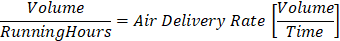
The optional Variable SpecificEnergy indicates how much electrical energy is consumed in the generation of a specific volume of compressed air. Usually, the SpecificEnergy uses the denominator 1 m³ or 1 l. The value is calculated according to the following formula:
The optional Variable SpecificEnergyCost indicates what the generation of a specific volume of compressed air costs. Usually, the SpecificEnergyCost uses the denominator 1 m³ or 1 l. The value is calculated according to the following formula:
The optional Variable HealthState describes if the Requirements of an Airnet can be fulfilled.
The optional Variable IntegratedState describes the degree of control over the compressors for compressed air generation.
The optional Variable OperatingState describes if the Requirements of an Airnet should be fulfilled.
The Variable OnOff of the OperationalType should not be used for an instance of this AirnetOperationalType.
The InstanceDeclarations of the AirnetOperationalType have additional Attributes defined in Table 98.
Table 98 – AirnetOperationalType Attribute values for child Nodes
|
Source Path |
Value Attribute |
Description Attribute |
|
AirDeliveryRate |
|
Volume of generated compressed air per time frame. |
|
CompressorsIntegrated |
|
Number of integrated compressors in the airnet. |
|
CompressorsIsolated |
|
Number of isolated compressors in the airnet. |
|
CompressorsNotAvailable |
|
Number of unavailable compressors in the airnet. |
|
ControlPressure |
|
Current pressure in the airnet. |
|
HealthState |
|
Actual health state of the airnet. |
|
IntegratedState |
|
Actual integrated state of the airnet. |
|
OperatingState |
|
Actual operating state of the airnet. |
|
SpecificEnergy |
|
Electrical energy consumed in the generation of a volume of compressed air. |
|
SpecificEnergyCost |
|
Costs for generating a volume of compressed air. |
|
VolumeFlowRateAvailable |
|
Measured or calculated available volume flow rate of the process fluid in the airnet. |
|
VolumeFlowRateUnavailable |
|
Calculated unavailable volume flow rate of the process fluid in the airnet. |
The CompressorOperationalType extends its supertype by compressor specific Variables and is formally defined in Table 99.
Table 99 – CompressorOperationalType Definition
|
Attribute |
Value |
||||
|
BrowseName |
CompressorOperationalType |
||||
|
IsAbstract |
False |
||||
|
References |
Node Class |
BrowseName |
DataType |
TypeDefinition |
Other |
|
Subtype of the OperationalType defined in 7.45, i.e. inheriting the InstanceDeclarations of that Node. |
|||||
|
0:HasComponent |
Variable |
ActivePressureBand |
0:UInt16 |
0:DataItemType |
O, RO |
|
0:HasComponent |
Variable |
FlowRateRatio |
0:Double |
0:BaseAnalogType |
O, RO |
|
0:HasComponent |
Variable |
IsentropicEfficiency |
0:Double |
0:BaseAnalogType |
O, RO |
|
0:HasComponent |
Variable |
SpecificEnergyRequirement |
0:Double |
0:BaseAnalogType |
O, RO |
|
|
|
|
|
|
|
|
The following nodes override nodes added by the OperationalType |
|||||
|
0:HasComponent |
Variable |
OperatingState |
CompressorOperatingStateEnum |
0:DataItemType |
O, RO |
The following illustration of a state machine does not imply the actual function or state machine for a compressor. It serves as an example of how the actual state machines may function.
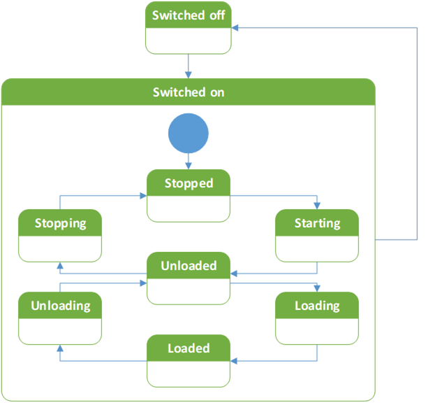
Figure 32 – CompressorOperationalType State Machine Illustration
The InstanceDeclarations of the CompressorOperationalType have additional Attributes defined in Table 100.
Table 100 – CompressorOperationalType Attribute values for child Nodes
|
Source Path |
Value Attribute |
Description |
|
ActivePressureBand |
|
Indicates the actual active pressure band. |
|
FlowRateRatio |
|
Calculated ratio of actual and maximum possible flow rate of a compressor. |
|
IsentropicEfficiency |
|
Calculated isentropic efficiency. |
|
OperatingState |
|
Actual operating state of the compressor. |
|
SpecificEnergyRequirement |
|
Calculated shaft input energy per unit of compressor actual rate of flow. |
The ConverterOperationalType extends its supertype by converter specific Variables and is formally defined in Table 101.
Table 101 – ConverterOperationalType Definition
|
Attribute |
Value |
||||
|
BrowseName |
ConverterOperationalType |
||||
|
IsAbstract |
False |
||||
|
References |
Node Class |
BrowseName |
DataType |
TypeDefinition |
Other |
|
Subtype of the OperationalType defined in 7.45, i.e. inheriting the InstanceDeclarations of that Node. |
|||||
|
0:HasComponent |
Variable |
CatalyticMaterialTemperature |
0:Double |
0:BaseAnalogType |
O, RO |
The InstanceDeclarations of the ConverterOperationalType have additional Attributes defined in Table 102.
Table 102 – ConverterOperationalType Attribute values for child Nodes
|
Source Path |
Value Attribute |
Description Attribute |
|
CatalyticMaterialTemperature |
|
Measured actual temperature of the catalytic material inside a converter. |
The DrainOperationalType provides extends its supertype by condensate drain specific Variables and is formally defined in Table 103.
Table 103 – DrainOperationalType Definition
|
Attribute |
Value |
||||
|
BrowseName |
DrainOperationalType |
||||
|
IsAbstract |
False |
||||
|
References |
Node Class |
BrowseName |
DataType |
TypeDefinition |
Other |
|
Subtype of the OperationalType defined in 7.45, i.e. inheriting the InstanceDeclarations of that Node. |
|||||
|
0:HasComponent |
Method |
DrainTest |
See 7.49.1 |
O |
|
The InstanceDeclarations of the DrainOperationalType have additional Attributes defined in Table 104.
Table 104 – DrainOperationalType Attribute values for child Nodes
|
Source Path |
Description Attribute |
|
DrainTest |
Invoke a drain test on a condensate drain. |
The Method DrainTest is used to trigger a test of the condensate drain via the Main Control System. The signature of this Method is specified below. There are no InputArguments or OutputArguments defined. Its formal representation in the AddressSpace is defined in Table 105.
Signature
DrainTest (
);
Table 105 – DrainTest Method AddressSpace Definition
|
Attribute |
Value |
||||
|
BrowseName |
DrainTest |
||||
|
References |
Node Class |
BrowseName |
DataType |
TypeDefinition |
ModellingRule |
|
|
|
|
|
|
|
The DryerOperationalType extends its supertype by dryer specific Variables and is formally defined in Table 106.
Table 106 – DryerOperationalType Definition
|
Attribute |
Value |
||||
|
BrowseName |
DryerOperationalType |
||||
|
IsAbstract |
False |
||||
|
References |
Node Class |
BrowseName |
DataType |
TypeDefinition |
Other |
|
Subtype of the OperationalType defined in 7.45, i.e. inheriting the InstanceDeclarations of that Node. |
|||||
|
0:HasComponent |
Variable |
PressureDewPoint |
0:Double |
0:BaseAnalogType |
O, RO |
|
|
|
|
|
|
|
|
The following nodes override nodes added by the OperationalType |
|||||
|
0:HasComponent |
Variable |
OnOff |
0:Boolean |
0:TwoStateDiscreteType |
O, RO |
|
0:HasComponent |
Variable |
OperatingState |
DryerOperatingStateEnum |
0:DataItemType |
O, RO |
The following illustrations of a state machines do not imply the actual function or state machines for dryers. It serves as an example of how the actual state machines may function.
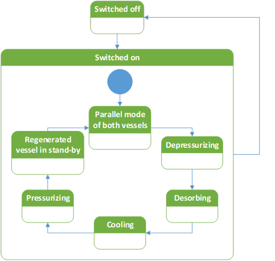
Figure 33 –DryerOperationalType Adsorption Dryer State Machine Illustration
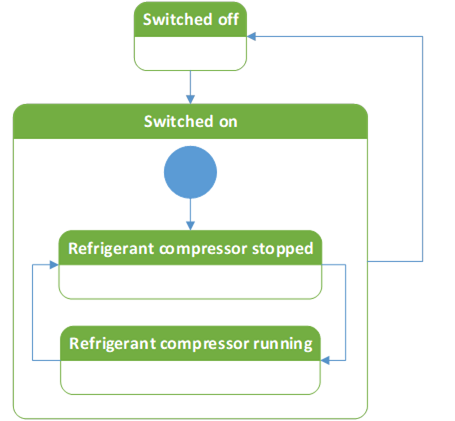
Figure 34 –DryerOperationalType Refrigerant Dryer State Machine Illustration
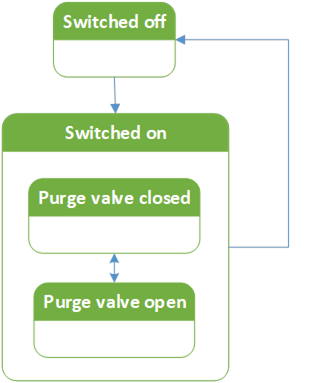
Figure 35 –DryerOperationalType Membrane Dryer State Machine Illustration
The InstanceDeclarations of the DryerOperationalType have additional Attributes defined in Table 107.
Table 107 – DryerOperationalType Attribute values for child Nodes
|
Source Path |
Value Attribute |
Description Attribute |
||
|
OnOff |
|
Actual OnOff state of the dryer. For membrane dryers this describes the state of the controller. |
||
|
|
“The dryer is switched off.” |
|
||
|
|
“The dryer is switched on.” |
|
||
|
OperatingState |
|
Actual operating state of the dryer. |
||
|
PressureDewPoint |
|
Measured or calculated actual pressure dew point of the process fluid at a dryer. |
The ValveOperationalType extends its supertype by valve specific Variables and is formally defined in Table 108.
Table 108 – ValveOperationalType Definition
|
Attribute |
Value |
||||
|
BrowseName |
ValveOperationalType |
||||
|
IsAbstract |
False |
||||
|
References |
Node Class |
BrowseName |
DataType |
TypeDefinition |
Other |
|
Subtype of the OperationalType defined in 7.45, i.e. inheriting the InstanceDeclarations of that Node. |
|||||
|
0:HasComponent |
Variable |
ContinuousPosition |
0:Double |
0:BaseAnalogType |
O, RO |
|
0:HasComponent |
Variable |
PortUsed |
0:UInt16 |
0:DataItemType |
O, RO |
Continuous valves shall use the Variable ContinuousPosition and define the EngineeringUnits Property.
Switching valves shall use the Variable PortUsed and define the EngineeringUnits Property as well as the Definition Property.
The InstanceDeclarations of the ValveOperationalType have additional Attributes defined in Table 109.
Table 109 – ValveOperationalType Attribute values for child Nodes
|
Source Path |
Value Attribute |
Description Attribute |
|
ContinuousPosition |
|
Actual valve stroke. |
|
PortUsed |
|
Actual port used. |
The StatisticsType provides Variables for statistics applications, such as counters, and is formally defined in Table 110.
Table 110 – StatisticsType Definition
|
Attribute |
Value |
||||
|
BrowseName |
StatisticsType |
||||
|
IsAbstract |
False |
||||
|
References |
Node Class |
BrowseName |
DataType |
TypeDefinition |
Other |
|
Subtype of the 2:FunctionalGroupType defined in OPC 10000-100, i.e. inheriting the InstanceDeclarations of that Node. |
|||||
|
0:HasSubtype |
ObjectType |
CompressorStatisticsType |
Defined in 7.53 |
||
|
|
|
|
|
|
|
|
0:HasInterface |
ObjectType |
3:IAggregateStatisticsType |
Defined in OPC 10000-200 |
||
|
|
|
|
|
|
|
|
0:HasComponent |
Variable |
RealTime |
0:Double |
0:BaseAnalogType |
O, RO |
|
0:HasComponent |
Variable |
RealTimeToNextService |
0:Double |
0:BaseAnalogType |
O, RO |
|
0:HasComponent |
Variable |
RunningTime |
0:Double |
0:BaseAnalogType |
O, RO |
|
0:HasComponent |
Variable |
RunningTimeToNextService |
0:Double |
0:BaseAnalogType |
O, RO |
|
|
|
|
|
|
|
|
Applied from 3:IAggregateStatisticsType |
|||||
|
0:HasProperty |
Variable |
3:ResetCondition |
0:String |
0:PropertyType |
O, RO |
|
0:HasComponent |
Method |
3:ResetStatistics |
O |
||
|
0:HasProperty |
Variable |
3:StartTime |
0:DateTime |
0:PropertyType |
O, RO |
The Variables ResetCondition and StartTime, and the Method ResetStatistics are defined by the IAggregateStatisticsType and shall be used as defined by the Interface.
The InstanceDeclarations of the StatisticsType have additional Attributes defined in Table 111.
Table 111 – StatisticsType Attribute values for child Nodes
|
Source Path |
Value Attribute |
Description Attribute |
|
RealTime |
|
Real time passed since last counter reset. |
|
RealTimeToNextService |
|
Real time left until the real time of the next service level is exceeded. |
|
RunningTime |
|
Time spent running since last counter reset. |
|
RunningTimeToNextService |
|
Running time left until the running time of the next service level is exceeded. |
The CompressorStatisticsType extends its supertype by compressor specific Variables and is formally defined in Table 112.
Table 112 – CompressorStatisticsType Definition
|
Attribute |
Value |
||||
|
BrowseName |
CompressorStatisticsType |
||||
|
IsAbstract |
False |
||||
|
References |
Node Class |
BrowseName |
DataType |
TypeDefinition |
Other |
|
Subtype of the StatisticsType defined in 7.52, i.e. inheriting the InstanceDeclarations of that Node. |
|||||
|
0:HasComponent |
Variable |
LoadedTime |
0:Double |
0:BaseAnalogType |
O, RO |
|
0:HasComponent |
Variable |
UnloadedTime |
0:Double |
0:BaseAnalogType |
O, RO |
The InstanceDeclarations of the CompressorStatisticsType have additional Attributes defined in Table 113.
Table 113 – CompressorStatisticsType Attribute values for child Nodes
|
Source Path |
Value Attribute |
Description Attribute |
|
LoadedTime |
|
Time spent in loaded state since last counter reset. |
|
UnloadedTime |
|
Time spent in unloaded state since last counter reset. |