
4 General information to AutoID and OPC UA
4.1 Introduction to AutoID
AutoID (Automatic Identification) technologies use mainly barcodes, OCR, 2D codes, RFID and NFC in order to identify all sorts of objects in all industry sectors and in logistics: articles in the super market, parts and modules in the production line, (returnable) transport items (RTI), vehicles and so forth. The main benefits of AutoID solutions are the acceleration of business processes and the improvement of data quality compared to manual procedures. AutoID systems rely on numbers, which identify the marked objects ("article number"). If it is required to distinguish similar objects uniquely from each other the article numbers must be extended by serial numbers.
While the automation of enterprise processes is rapidly growing the AutoID technologies achieve a crucial meaning. Concepts like the Internet of Things (IoT) or "Industrie 4.0" can only be put into practice successfully, if AutoID systems provide reliable data about all kinds of moving objects in the diversity of business processes, production lines and logistics chains. This data must be transferred securely to the IT systems in the background which control the processes, take actions if discrepancies are detected and post alerts to managers if human actions are required.
Talking about AutoID today means not to stay with the mere automatic identification of objects. It is also important to collect information about further parameters of moved or stationary goods. Therefore, critical goods are not only equipped with RFID tags, but also with sensors which record parameters like temperature, humidity, acceleration (to detect shocks), etc. Such functionality helps to make sure, that goods do not only reach their goal, but also keep appropriate properties so that they can be sold in the super market or mounted at the production line.
After identification and sensing there is a third vital requirement in modern logistics and production environments: real-time locating systems (RTLS). Primarily, people think of GPS systems to provide real-time locating. But GPS has its limits. For instance a truck approaching a distribution centre cannot make sure to hit the right hub when just using GPS. For the last meters towards the hub this truck would need complementary components based on e. g. active RFID or RTLS.
The collaboration of AIM Germany and OPC Foundation aims at the easy systems integration of all these AutoID components and at an easy way to improve and substitute systems according to new requirements and market developments.
4.2 Introduction to OPC Unified Architecture
4.2.1 General
The main use case for OPC classic specifications is the online data exchange between devices and HMI or SCADA systems using Data Access functionality. In this use case the device data is provided by an OPC server and is consumed by an OPC client integrated into the HMI or SCADA system. OPC DA provides functionality to browse through a hierarchical namespaces containing data items and to read, write and to monitor these items for data changes. The OPC classic specifications are based on Microsoft COM/DCOM technology for the communication between software components from different vendors. Therefore OPC classic server and clients are restricted to Windows PC based automation systems.
OPC UA incorporates all features of OPC classic specifications like OPC DA, A&E and HDA but defines platform independent and secure communication mechanisms and generic, extensible and object-oriented modelling capabilities for the information a system wants to expose. OPC UA is directly integrated into devices and is used for configuration, diagnostic and maintenance use cases in addition to online data exchange. OPC UA is an integrated communication interface used from sensor level devices up to enterprise applications.
The OPC 10000-6 defines different transport mechanisms optimized for different use cases. The first version of OPC UA is defining an optimized binary TCP protocol for high performance intranet communication as well as a mapping to accepted internet standards like Web Services. The abstract communication model does not depend on a specific protocol mapping and allows adding new protocols in the future. Features like security and reliability are directly built into the transport mechanisms. Based on the platform independence of the protocols, OPC UA servers and clients can be directly integrated into devices and controllers.
The OPC UA Information Model provides a standard way for Servers to expose Objects to Clients. Objects in OPC UA terms are composed of other Objects, Variables and Methods. OPC UA also allows relationships to other Objects to be expressed.
The set of Objects and related information that an OPC UA Server makes available to Clients is referred to as its AddressSpace. The elements of the OPC UA Object Model are represented in the AddressSpace as a set of Nodes described by Attributes and interconnected by References. OPC UA defines eight classes of Nodes to represent AddressSpace components. The classes are Object, Variable, Method, ObjectType, DataType, ReferenceType and View. Each NodeClass has a defined set of Attributes.
This specification defines Nodes of the OPC UA NodeClasses Object, Method, Variable, ObjectType and DataType.
Objects are used to represent components of a system. An Object is associated to a corresponding ObjectType that provides definitions for that Object.
Methods are used to represent commands or services of a system.
Variables are used to represent values. Two categories of Variables are defined, Properties and DataVariables.
Properties are Server-defined characteristics of Objects, DataVariables and other Nodes. Properties are not allowed to have Properties defined for them. An example for Properties of Objects is the DeviceLocation Property of an AutoIdDeviceType ObjectType.
DataVariables represent the data contents of an Object.
4.2.2 Graphical Notation
OPC UA defines a graphical notation for an OPC UA AddressSpace. It defines graphical symbols for all NodeClasses and how different types of References between Nodes can be visualized. Figure 1 shows the symbols for the six NodeClasses used in this specification. NodeClasses representing types always have a shadow.
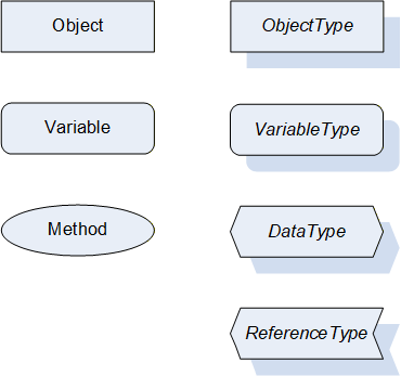
Figure 2 shows the symbols for the ReferenceTypes used in this specification. The Reference symbol is normally pointing from the source Node to the target Node. The only exception is the HasSubtype Reference. The most important References like HasComponent, HasProperty, HasTypeDefinition and HasSubtype have special symbols avoiding the name of the Reference. For other ReferenceTypes or derived ReferenceTypes the name of the ReferenceType is used together with the symbol.
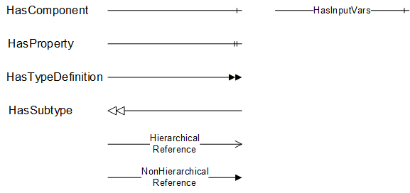
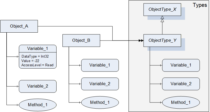
Figure 3 shows a typical example for the use of the graphical notation. Object_A and Object_B are instances of the ObjectType_Y indicated by the HasTypeDefinition References. The ObjectType_Y is derived from ObjectType_X indicated by the HasSubtype Reference. The Object_A has the components Variable_1, Variable_2 and Method_1.
To describe the components of an Object on the ObjectType the same NodeClasses and References are used on the Object and on the ObjectType like for ObjectType_Y in the example. The instance Nodes used to describe an ObjectType are instance declaration Nodes.
To provide more detailed information for a Node, a subset or all Attributes and their values can be added to a graphical symbol.
4.3 Use Cases
AutoID Devices like RFID or optical readers and RTLS are used in several applications, from production control to material flow, logistics, asset management, and more. In all of these applications, the AutoID Devices have to scan the environment and read / decode the given object ids.
In addition, the object ids can be altered in case of RFID and RTLS systems.
If a RFID transponder provides additional memory, these data areas might be read and written.
In case of RTLS, the host system may ask the RTLS for the current position of a given object transponder.
The information delivered by AutoID systems can be used by host systems as PC applications, mobile applications, IT systems, programmable logic controllers (PLC), and more.