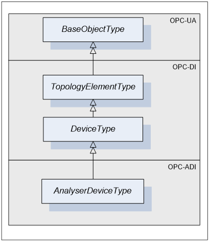
AnalyserDeviceType defines the general structure of an AnalyserDevice Object. Figure 3, Figure 4 and Figure 5 show the inheritance hierarchy and detailed composition of AnalyserDeviceType. It is formally defined in Table 1.
AnalyserDeviceType is a subtype of DeviceType [OPC 10000-100] and as such can have Parameters which are kept in an Object called ParameterSet. Parameters represented by <ParameterIdentifier > and their list called ParameterSet are inherited from DeviceType.
TopologyElementType [OPC 10000-100] introduced a component called MethodSet, which can be used to organize Methods exposed to the Client. AnalyserDeviceType takes advantage of that inherited component and groups all of its Methods under MethodSet.
DeviceType also introduces FunctionalGroups identified by <GroupIdentifier> that expose its Parameters in an organized fashion reflecting the structure of the device. AnalyserDeviceType can have any number of FunctionalGroups.
AnalyserDeviceType defines three mandatory FunctionalGroups:
- Configuration - used to organize Parameters representing the high-level configuration items of the analyser, which are expected to be modified by end users.
- Status - used to organize Parameters which describe the general health of the analyser.
- FactorySettings - used to organize Parameters, which describe the factory settings of the analyser that are not expected to be modified by end users.
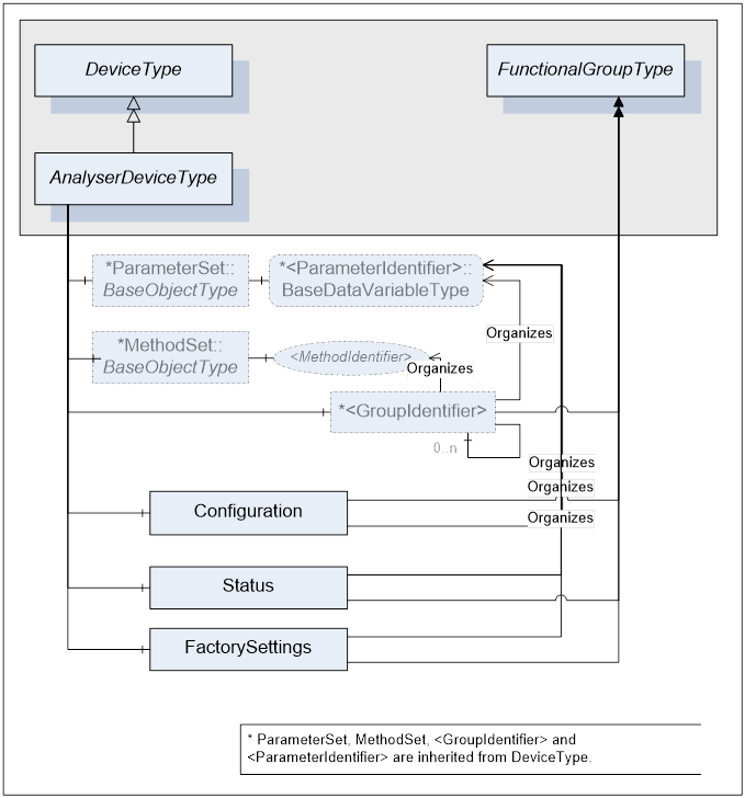
Figure 4 – AnalyserDeviceType Components
The AnalyserDevice Object that represents an analyser has one or more AnalyserChannels. AnalyserChannel is described in clause 5.2.2. The AnalyserChannel Node instances are identified by <ChannelIndentifier> browse name.
AnalyserDevice Object has zero or more Objects of type AccessorySlotType and identified by <AccessorySlotIdentifier>. AccessorySlotType is described in clause5.2.4. AccessorySlot Objects represent physical locations on the analyser where the analytical accessory can be mounted. Accessories currently mounted on the analyser device as well as the supported accessories for the accessory slot are represented as components of the AccessorySlot Object. For details refer to clause 5.2.3.
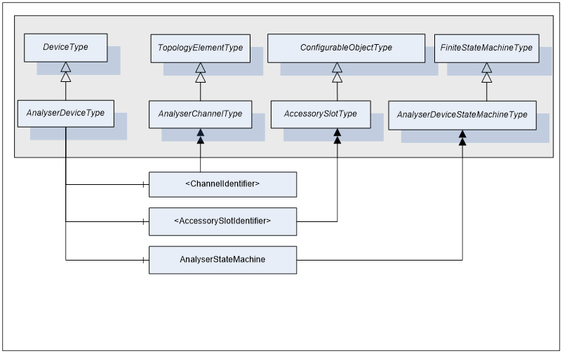
Figure 5 - AnalyserDeviceType Components cont.
AnalyserDeviceType does not expose any mandatory Parameters to report or manipulate the state of an analyser device. Instead, AnalyserDevice states are exposed through the AnalyserStateMachine component of type AnalyserDeviceStateMachineType. For details on AnalyserDeviceStateMachineType see clause 5.3.2.
Table 1 - AnalyserDeviceType Definition
|
Attribute |
Value |
|||||
|
BrowseName |
AnalyserDeviceType |
|||||
|
IsAbstract |
True |
|||||
|
References |
NodeClass |
BrowseName |
DataType |
TypeDefinition |
ModellingRule |
|
|
Subtype of the DeviceType defined in [OPC 10000-100] |
||||||
|
HasSubtype |
ObjectType |
SpectrometerDeviceType |
Defined in Clause 5.2.6.1 |
|||
|
HasSubtype |
ObjectType |
ParticleSizeMonitorDeviceType |
Defined in Clause 5.2.8.1 |
|||
|
HasSubtype |
ObjectType |
AcousticSpectrometerDeviceType |
Defined in Clause 5.2.9.1 |
|||
|
HasSubtype |
ObjectType |
MassSpectrometerDeviceType |
Defined in Clause 5.2.7.1 |
|||
|
HasSubtype |
ObjectType |
ChromatographDeviceType |
Defined in Clause 5.2.10.1 |
|||
|
HasSubtype |
ObjectType |
NMRDeviceType |
Defined in Clause 5.2.11.1 |
|||
|
|
|
|
|
|||
|
HasComponent |
Object |
Configuration |
|
FunctionalGroupType |
Mandatory |
|
|
HasComponent |
Object |
Status |
|
FunctionalGroupType |
Mandatory |
|
|
HasComponent |
Object |
FactorySettings |
|
FunctionalGroupType |
Mandatory |
|
|
HasComponent |
Object |
<ChannelIdentifier> |
|
AnalyserChannelType |
OptionalPlaceHolder |
|
|
HasComponent |
Object |
<AccessorySlotIdentifier> |
|
AccessorySlotType |
OptionalPlaceHolder |
|
|
HasComponent |
Object |
AnalyserStateMachine |
|
AnalyserDeviceStateMachineType |
Mandatory |
|
|
|
|
|
|
|
|
|
|
AnalyserDeviceType.MethodSet |
||||||
|
HasComponent |
Method |
GetConfiguration |
|
|
Mandatory |
|
|
HasComponent |
Method |
SetConfiguration |
|
|
Mandatory |
|
|
HasComponent |
Method |
GetConfigDataDigest |
|
|
Mandatory |
|
|
HasComponent |
Method |
CompareConfigDataDigest |
|
|
Mandatory |
|
|
HasComponent |
Method |
ResetAllChannels |
|
|
Mandatory |
|
|
HasComponent |
Method |
StartAllChannels |
|
|
Mandatory |
|
|
HasComponent |
Method |
StopAllChannels |
|
|
Mandatory |
|
|
HasComponent |
Method |
AbortAllChannels |
|
|
Mandatory |
|
|
HasComponent |
Method |
GotoOperating |
|
|
Mandatory |
|
|
HasComponent |
Method |
GotoMaintenance |
|
|
Mandatory |
|
AnalyserDeviceType is a subtype of DeviceType defined in [OPC 10000-100] and as such it inherits DeviceType’s characteristics. For a complete definition of the DeviceType see [OPC 10000-100].
The AnalyserDeviceType ObjectType is abstract. There will be no instances of an AnalyserDeviceType itself, but there will be instances of sub-types of this type. In this specification, the term AnalyserDevice generically refers to an instance of any ObjectType derived from the AnalyserDeviceType ObjectType.
All AnalyserDevices have Attributes and Properties that they inherit from the DeviceType. For those elements, the same rules as defined for Device Objects in [OPC 10000-100] apply.
The sub types of the AnalyserDeviceType are illustrated in Figure 6. Each of these sub type may be further sub typed.
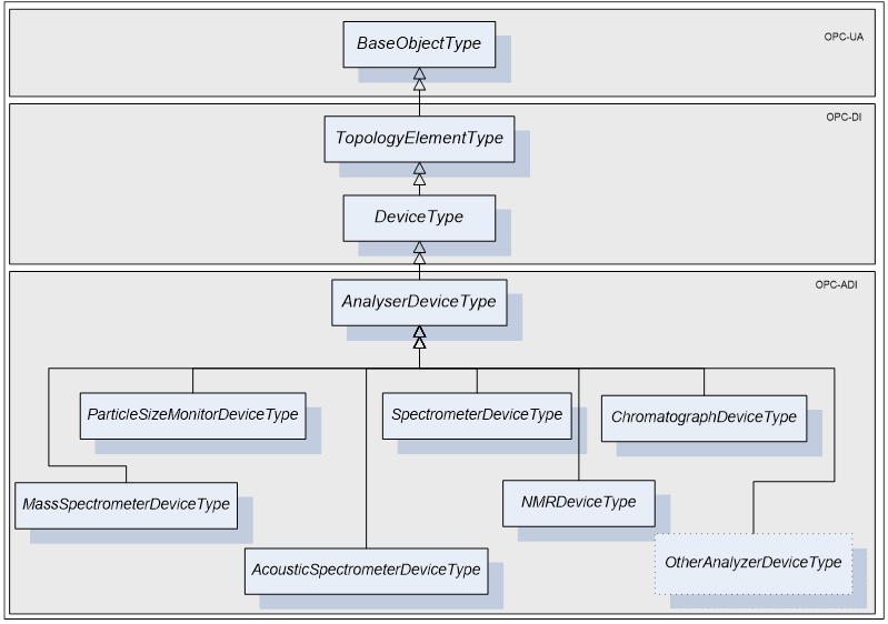
Figure 6 - AnalyserDeviceType Hierarchy
The AnalyserDeviceType is derived from the DeviceType as an Abstract type. It is sub-typed for each one of the analyser classes. Six sub-types are introduced:
Table 2 –AnalyserDeviceType Sub-type definition
|
AnalyserDeviceType |
Description |
|
SpectrometerDeviceType |
A light spectrometer is an optical instrument used to measure Properties of light over a specific portion of the electromagnetic spectrum (IR/NIR/VIS/UV), typically used in spectroscopic analysis to identify chemical composition of sample materials. The use of analytical techniques to determine process control parameters from spectra allows a wide range of industrial applications. This type covers FTIR, diode array, etc. |
|
AcousticSpectrometerDeviceType |
An acoustic spectrometer uses sound wave emission and advanced pattern recognition software to predict the physical Properties of powders and particulates. This type of analyser uses high frequency sounds emitted by all physical and chemical processes (particle impact, turbulent gas flow, gas evolution, fermentation, cavitation and multiphase flow). It is a non-invasive technique which is responding to dynamic event making it suitable for process control. |
|
MassSpectrometerDeviceType |
A mass spectrometer is an analytical instrument used to measure the mass-to-charge ratio of ions. It is most generally used to find the composition of a physical sample by generating a mass spectrum representing the masses of sample components. A wide range of industrial process control applications are therefore possible, such as the online control of solvent drying. |
|
ParticleSizeMonitorDeviceType |
Particle size can be determined by light scattering (e.g. Focus Beam Reflectance Measurement) or other Methods. This type of analyser can be used to implement particle monitoring technique for in-line real-time measurement of particle size. A wide range of industrial process control applications are therefore possible such as the online control of crystallizers |
|
ChromatographDeviceType |
Chromatography is the collective term for a family of techniques for the separation of mixtures. It involves passing a mixture dissolved in a "mobile phase" through a stationary phase, which separates the analyte to be measured from other molecules in the mixture and allows it to be isolated. Chromatography may be preparative or analytical. Preparative chromatography seeks to separate the components of a mixture for further use (and is thus a form of purification). Analytical chromatography normally operates with smaller amounts of material and seeks to measure the relative proportions of analytes in a mixture. The two are not mutually exclusive |
|
NMRDeviceType |
Nuclear Magnetic Resonance spectrometers |
|
|
|
Parameters defined for the AnalyserDeviceType are described in the following tables. The tables correspond to mandatory FunctionalGroups defined for the AnalyserDeviceType. Additional Parameters may be defined on subtypes of AnalyserDeviceType and associated with those FunctionalGroups.
All AnalyserDevice Parameters exist as components of ParameterSet Object defined on that AnalyserDevice through inheritance from DeviceType. Each Parameter defined for an AnalyserDevice shall be accessible through one or more FunctionalGroup defined on that AnalyserDevice. Note, that the same Parameter is not instantiated more than once. Both, ParameterSet and a specific FunctionalGroup maintain References to the same instance of the Parameter.
Table 3 shows Parameters that will be organized by the Configuration FunctionalGroup.
Table 3 – AnalyserDevice Configuration Parameters
|
BrowseName |
Description |
VariableType |
Optional/ Mandatory |
|
ConfigData |
Optional representation of the AnalyserDevice configuration |
FileType
|
O |
|
|
|
|
|
ConfigData is an optional representation of the AnalyserDevice configuration. When it is present, it may be used to read and write the AnalyserDevice configuration in chunks. The main purpose of this element is to provide a way to read and write configuration that are larger than the maximum size of the OPC UA message. Reading and writing configuration through this object are subject to the same state machine constraints as GetConfiguration and SetConfiguration.
To maintain configuration consistency, the server must grant read and write access to one and only one user at any given time.
The steps to update the configuration through the ConfigData object are:
- When SetConfiguration is allowed based on the state machine states, a single user may cal “open” the ConfigData. If an “Open” is attempted when not permitted, the server shall return “Bad_InvalidState”.
- The user updates the configuration by calling repeatitively and in increasing order “write” method on ConfigData. If the “Write” are not sequential, the server shall return “Bad_InvalidArgument”.
- When the whole configuration has been written, the user calls “close” method on the ConfigData.
- The server is responsible to verify the configuration. If an error occurs during the verification, the server shall return “Bad_InvalidArgument” on the “Close”. In case of error, the previous configuration is restored.
- The server commits the new configuration. . If an error occurs during the commit, the server shall return “Bad_InvalidArgument” on the “Close”. In case of error, the previous configuration is restored.
Table 4 shows Parameters that will be organized by the Status FunctionalGroup. All Parameters organized by this FunctionalGroup shall be read-only.
Table 4 – AnalyserDevice Status Parameters
|
BrowseName |
Description |
VariableType |
Optional/ Mandatory |
|
DiagnosticStatus |
General health status of the analyser |
DataItemType DataType=DeviceHealthEnumeration
|
M |
|
|
|
|
|
The DiagnosticStatus Parameter reflects the general health of analyser. It is defined as a Variable of DataItemType type and its possible values are defined by [OPC 10000-100] enumerationDeviceHealthEnumeration. Its value must be the same as DeviceType.DeviceHealth Property.
Table 5 shows Parameters that will be organized by the FactorySettings FunctionalGroup component of the AnalyserDeviceType.
Table 5 – AnalyserDevice FactorySettings Parameters
|
BrowseName |
Description |
VariableType |
Optional/ Mandatory |
|
|
|
|
|
The SerialNumber, Manufacturer, Model, DeviceManual, DeviceRevision, SoftwareRevision and the HardwareRevision Properties are defined on DeviceType and as such available on AnalyserDeviceType. As a general rule, they are read-only properties. However, they can be updated to reflect changes made to the analyser configuration e.g. upgrading the firmware.
DeviceRevision Property will be used to indicate an overall change in the analyser. It is mandatory and shall be updated automatically or manually each time the analyser configuration is altered. It is the customer’s QA responsibility to determine if this particular change affects the validation of the analyser.
The RevisionCounter Property is an incremental counter indicating the number of times the semi-static data within the AnalyserDevice has been modified.
If the analytical device represented by an AnalyserDevice Object is unable to publish a value for a mandatory Parameter defined in Table 5, the Analyser Server should provide a way to manually enter that value.
All Methods defined for AnalyserDeviceType and its state machines are grouped under the MethodSet component inherited from DeviceType [OPC 10000-100].
AnalyserDeviceType defines a Method called GetConfiguration, which is used to read the complete configuration of the AnalyserDevice and all of its components (AnalyserChannel, Accessory, AccessorySlot etc.) from the Analyser Server. The configuration is a proprietary structure defined by the analyser vendor, and is represented as a ByteString.
AnalyserDeviceType defines a Method called SetConfiguration, which is used to write the complete configuration of the AnalyserDevice and all of its components to the Analyser Server. This Method can be executed only when all of the AnalyserChannels are in a Stopped state or in a Maintenance state (see 5.3.4.3). An attempt to call it while in any other state results in a failure of the Method call.
When the SetConfiguration Method is executed, it automatically causes a transition of all AnalyserChannels in a Stopped state to the Resetting state and the new configuration becomes active. The configuration is a structure provided by the analyser vendor, and represented as a ByteString.
Even if the ADI Client verifies the configuration before calling the SetConfiguration Method, the Analyser Server has the ultimate responsibility to verify the configuration (Parameter ranges, Parameter values relating to each other, Parameter values in regard to installed hardware) before applying the requested changes. If any Parameter value is invalid, the whole configuration shall be rejected.
If an error occurs during a method call, the analyser state should be returned the same as before the call or at least a stable state.
Table 6 – GetConfiguration Method
|
Method |
Description |
|||
|
GetConfiguration |
Read the complete configuration of the AnalyserDevice and all of its components to the Analyser Server. |
|||
|
|
InputArguments |
|||
|
|
Name |
DataType |
ValueRank / arrayDimension |
Description |
|
|
|
N/A |
N/A |
|
|
|
OutputArguments |
|||
|
|
||||
|
|
ConfigData |
ByteString |
-1/[0] |
Configuration structure represented as a single dimensional array of Bytes. Length of an array is provided by the Server at runtime. If the size of ConfigData parameter is larger than a single OPC UA message, the AnalyserDevice.ConfigData object shall be used. |
Table 7 – SetConfiguration Method
|
Method |
Description |
|||
|
SetConfiguration |
Write the complete configuration of the AnalyserDevice and all of its components to the Analyser Server and make the new configuration active. |
|||
|
|
InputArguments |
|||
|
|
Name |
DataType |
ValueRank / arrayDimension |
Description |
|
|
ConfigData |
ByteString |
-1/[0] |
Configuration structure represented as a single dimensional array of Bytes. Length of an array is provided by the Client at runtime. If the size of ConfigData parameter is larger than a single OPC UA message, the AnalyserDevice.ConfigData object shall be used. |
|
|
OutputArguments |
|||
|
|
||||
|
|
ConfigDataDigest |
String |
-1/[0] |
Vendor specific digest (like SHA1) of the ConfigData. It is calculated, by the Server, after ConfigData is received and before any change has been made. It is used as the reference to know if the configuration has been altered after the SetConfiguration call. This string is intended to be human readable for example the hexadecimal or Base64 representation of the SHA1. |
AnalyserDevice defines a Method called GetConfigDataDigest, which is used to read the digest (e.g. SHA1 hash) of the complete analyser configuration. The digest is returned in a Method argument called ConfigDataDigest. It represents the same data which is calculated by the Server, when SetConfiguration Method is called. The value returned in ConfigDataDigest will change when the configuration of the analyser is changed in a way that may alter the results it produces. Examples of analyser changes that may affect the value of ConfigDataDigest are:
- A configuration Parameter of the analyser or any of its components is modified. There are rare cases where a change of a Parameter does not affect the analyser results like setting an acquisition trigger. In these cases the ConfigDataDigest shall not be recomputed. The vendor shall clearly specify which Parameters do not affect ConfigDataDigest.
- A Method call which does not update Parameters but alters behaviour of the analyser (e.g. firmware update) is called. The vendor shall clearly specify which Methods affect the returned value from ConfigDataDigest
- An accessory is added or removed
- Analyser is configured locally via built-in panel.
By comparing the ConfigDataDigest output argument from the SetConfiguration Method with the current value returned in the ConfigDataDigest argument of the GetConfigDataDigest Method, a Client shall be able to determine if the analyser configuration has been modified in such a way that the results produced by the analyser may be different than expected.
Table 8 – GetConfigDataDigest Method
|
Method |
Description |
|||
|
GetConfigDataDigest |
Read the digest of the complete analyser configuration as computed by the Server. |
|||
|
|
InputArguments |
|||
|
|
Name |
DataType |
ValueRank / arrayDimension |
Description |
|
|
None |
N/A |
N/A |
|
|
|
OutputArguments |
|||
|
|
||||
|
|
ConfigDataDigest |
String |
-1/[0] |
Vendor specific digest (like SHA1) of the complete analyser configuration. It is used as the reference to know if the configuration has been altered after the last SetConfiguration call. This string is intended to be human readable for example the hexadecimal or Base64 representation of the SHA1. |
A Method called CompareConfigDataDigest can be used to ask the AnalyserDevice if the ConfigDataDigest held by the Client reflects the current configuration of the analyser. This approach relieves the client from the responsibility for comparing the configuration digests.
Table 9 – CompareConfigDataDigest Method
|
Method |
Description |
|||
|
CompareConfigDataDigest |
Compare the provided ConfigDataDigest with the actual one of the analyser. |
|||
|
|
InputArguments |
|||
|
|
Name |
DataType |
ValueRank / arrayDimension |
Description |
|
|
ConfigDataDigest |
String |
-1/[0] |
Vendor specific digest (like SHA1) of the complete analyser configuration as returned by SetConfiguration and GetConfigurationDataDigest. This string is intended to be human readable for example the hexadecimal or Base64 representation of the SHA1. |
|
|
OutputArguments |
|||
|
|
||||
|
|
IsEqual |
Boolean |
-1/[0] |
True if the input ConfigDataDigest is equal to the actual digest of the analyser configuration. |
AnalyserDeviceType defines several Methods used for simultaneous control of analyser channels. Those Methods are defined in the following tables.
Table 10 – ResetAllChannels Method
|
Method |
Description |
|
ResetAllChannels |
Reset all AnalyserChannels belonging to this AnalyserDevice. |
|
|
InputArguments: NONE |
|
|
OutputArguments: NONE |
Table 11 – StartAllChannels Method
|
Method |
Description |
|
StartAllChannels |
Start all AnalyserChannels belonging to this AnalyserDevice. |
|
|
InputArguments: NONE |
|
|
OutputArguments: NONE |
Table 12 – StopAllChannels Method
|
Method |
Description |
|
StopAllChannels |
Stop all AnalyserChannels belonging to this AnalyserDevice. |
|
|
InputArguments: NONE |
|
|
OutputArguments: NONE |
Table 13 – AbortAllChannels Method
|
Method |
Description |
|
AbortAllChannels |
Abort all AnalyserChannels belonging to this AnalyserDevice. |
|
|
InputArguments: NONE |
|
|
OutputArguments: NONE |
Methods described in Table 10, Table 11, Table 12, Table 13 operate on all AnalyserChannels that are in the Operating state and their Configuration.IsEnabled Parameter is set to True. These Methods are not guaranteed to be atomic and their effect on each AnalyserChannel is not necessarily simultaneous. For example, the following implementation is perfectly legal:
|
For each AnalyserChannel If AnalyserChannel.IsInOperatingState AND AnalyserChannel.Configuration.IsEnabled == TRUE AnalyserChannel.Reset ()
|
Table 14 - GotoOperating Method
|
Method |
Description |
|
GotoOperating |
Causes the AnalyserDeviceStateMachine to go to Operating state, forcing all AnalyserChannels to leave the SlaveMode state and go to the Operating state. |
|
|
InputArguments: NONE |
|
|
OutputArguments: NONE |
Table 15 - GotoMaintenance Method
|
Method |
Description |
|
GotoMaintenance |
Causes the AnalyserDeviceStateMachine to go to Maintenance state, forcing all AnalyserChannels to SlaveMode state.. |
|
|
InputArguments: NONE |
|
|
OutputArguments: NONE |
Table 16 – Method result codes for AnalyserDeviceType methods
|
Result code |
Description |
|
Bad_InvalidArgument |
One or more argument re invalid. |
|
Bad_InvalidState |
Method called when the analyser is not in the appropriate state. |
|
Bad_RequestTooLarge |
The request message size exceeds limits set by the server. |
|
Bad_ResponseTooLarge |
The response message size exceeds limits set by the client. |
|
Bad_ServiceUnsupported |
The analyser does not support the requested service. |
|
Bad_UnexpectedError |
An unexpected error occurred. |
This ObjectType defines the structure of an AnalyserChannel Object. Figure 7 depicts the AnalyserChannelType hierarchy. Figure 8 and Figure 9 show the AnalyserChannelType components. It is formally defined in Table 17.
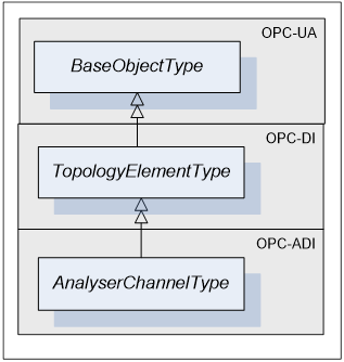
Figure 7 - AnalyserChannelType
AnalyserChannelType is a subtype of TopologyElementType.
An AnalyserChannel may have Parameters. If an AnalyserChannel has Parameters they appear in an Object called ParameterSet as a flat list of Parameters. ParameterSet is inherited from TopologyElementType [OPC 10000-100]. Parameters of an AnalyserChannel are identified by the <ParameterIdentifier> browse name.
TopologyElementType [OPC 10000-100] introduces a component called MethodSet, which shall be used to organize Methods exposed to the Client. AnalyserChannelType takes advantage of that inherited component and groups all of its Methods and the ones from its substate machines under MethodSet.
Parameters of an AnalyserChannel can be organized in FunctionalGroups identified as <GroupIdentifier> browse name.
AnalyserChannelType defines two mandatory FunctionalGroups (see clause 5.2.1.4 for details):
- Configuration - used to organize Parameters representing the high-level configuration items of the channel, which are expected to be modified by end users.
- Status - used to organize Parameters which describe the general health of the channel.
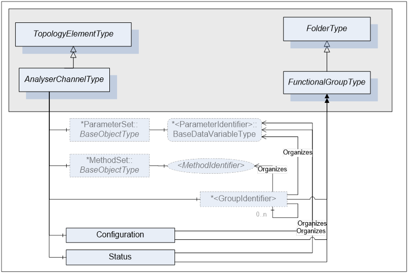
Figure 8 - AnalyserChannelType FunctionalGroups
AnalyserChannel Object has zero or more Objects of type AccessorySlotType and identified by <AccessorySlotIdentifier> browse name. AccessorySlotType is described in clause 5.2.3. AccessorySlot Objects represent physical locations on the physical channel where the analytical accessory can be mounted. Accessories currently mounted on the analyser channel as well as the supported accessories for the AccessorySlot are defined as components of the AccessorySlot Object. For details refer to clause 5.2.3.
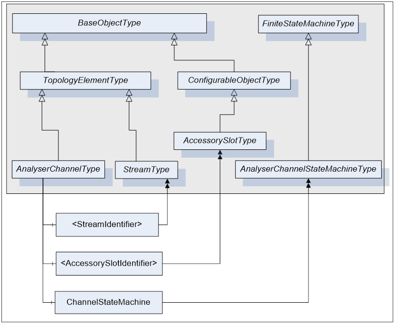
Figure 9 - AnalyserChannelType Components
AnalyserChannelType does not expose any mandatory Parameters to report or manipulate the state of an AnalyserChannel. Instead, AnalyserChannel states are exposed through the ChannelStateMachine Object of the type AnalyserChannelStateMachineType. For details on AnalyserChannelStateMachineType see clause 5.3.2.
Table 17 – AnalyserChannelType Definition
|
Attribute |
Value |
|||||
|
BrowseName |
AnalyserChannelType |
|||||
|
IsAbstract |
False |
|||||
|
References |
NodeClass |
BrowseName |
DataType |
TypeDefinition |
ModellingRule |
|
|
Subtype of the TopologyElementType defined in [OPC 10000-100]. |
||||||
|
HasComponent |
Object |
ParameterSet |
|
BaseObjectType |
Mandatory |
|
|
|
|
|
|
|
|
|
|
HasComponent |
Object |
<GroupIdentifier> |
|
FunctionalGroupType |
OptionalPlaceHolder |
|
|
HasComponent |
Object |
Configuration |
|
FunctionalGroupType |
Mandatory |
|
|
HasComponent |
Object |
Status |
|
FunctionalGroupType |
Mandatory |
|
|
HasComponent |
Object |
<StreamIdentifier> |
|
StreamType |
OptionalPlaceHolder |
|
|
HasComponent |
Object |
<AccessorySlotIdentifier> |
|
AccessorySlotType |
OptionalPlaceHolder |
|
|
HasComponent |
Object |
ChannelStateMachine |
|
AnalyserChannelStateMachineType |
Mandatory |
|
|
|
|
|
|
|
|
|
|
AnalyserChannelType.MethodSet |
||||||
|
HasComponent |
Method |
GotoOperating |
|
|
Mandatory |
|
|
HasComponent |
Method |
GotoMaintenance |
|
|
Mandatory |
|
|
HasComponent |
Method |
StartSingleAcquisition |
|
|
Mandatory |
|
|
HasComponent |
Method |
Reset |
|
|
Mandatory |
|
|
HasComponent |
Method |
Start |
|
|
Mandatory |
|
|
HasComponent |
Method |
Stop |
|
|
Mandatory |
|
|
HasComponent |
Method |
Hold |
|
|
Mandatory |
|
|
HasComponent |
Method |
Unhold |
|
|
Mandatory |
|
|
HasComponent |
Method |
Suspend |
|
|
Mandatory |
|
|
HasComponent |
Method |
Unsuspend |
|
|
Mandatory |
|
|
HasComponent |
Method |
Abort |
|
|
Mandatory |
|
|
HasComponent |
Method |
Clear |
|
|
Mandatory |
|
The term AnalyserChannel refers to an instance of the AnalyserChannelType ObjectType as defined in Table 17.
All AnalyserChannels have Attributes and Properties inherited from the BaseObject.
Each AnalyserDevice Object has at least one AnalyserChannel Object as its component.
Parameters defined for the AnalyserChannelType are described in the following tables. The tables correspond to mandatory FunctionalGroups defined for the AnalyserChannelType. Additional Parameters may be defined for AnalyserChannel on subtypes of AnalyserDeviceType and associated with those FunctionalGroups.
All AnalyserChannel Parameters exist as components of the ParameterSet Object defined on that AnalyserChannel. Each Parameter defined for an AnalyserChannel shall be accessible through one and only one FunctionalGroup defined on that AnalyserChannel. Note, that the same Parameter is not instantiated more than once. Both, ParameterSet and a specific FunctionalGroup maintain References to the same instance of the Parameter.
Table 18 shows Parameters that will be organized by the Configuration FunctionalGroup.
Table 18 – AnalyserChannel Configuration Parameters
|
BrowseName |
Description |
VariableType |
Optional/ Mandatory |
|
ChannelId |
Channel Id defined by user. On some analysers, the name of a channel may be configured using a maintenance tool, which leads to having two names to refer to the same channel for example: Channel1 and FirstChannel. In this case, one is for the BrowseName and the second is the ChannelId. |
DataItemType (DataType=String) |
O |
|
IsEnabled |
True if this AnalyserChannel maybe used to perform acquisition. Allow an AnalyserChannel to be marked as “not in use” so xxxAllChannels Methods of the AnalyserDevice may skip it. In the case of “software” AnalyserChannel like GC, this allows a chromatographic application to be disabled. |
DataItemType (DataType=Boolean) |
M |
Table 19 shows Parameters that will be organized by Status FunctionalGroup. All Parameters organized by this FunctionalGroup shall be read-only.
Table 19 – AnalyserChannel Status Parameters
|
BrowseName |
Description |
VariableType |
Optional/ Mandatory |
|
DiagnosticStatus |
AnalyserChannel health status |
(DataType=DeviceHealthEnumeration) |
M |
|
ActiveStream |
Active stream for this AnalyserChannel. Its value is the BrowseName of the active stream. If no Stream is active, it shall be set to NULL. |
DataItemType (DataType=String) |
M |
The DiagnosticStatus Parameter reflects the general health of the channel. It is defined as a Variable of DataItemType type and its value is defined by [OPC 10000-100] enumeration DeviceHealthEnumeration.
All Methods defined for AnalyserChannelType and its substate machines are grouped under the MethodSet component inherited from TopologyElementType [OPC 10000-100].
AnalyserChannel defines a Method called StartSingleAcquisition, which is used to start a single data acquisition, which uses current values of Parameters from the AcquisitionSettings FunctionalGroup of the Stream indicated by SelectedStream argument. The Method argument ExecutionCycle is used to indicate what it is that the acquisition is collecting e.g. sample, background, and dark noise.
If an error occurs during a method call, the analyser state should be the same as before the call.
Table 20 – StartSingleAcquisition Method
|
Method |
Description |
|||
|
StartSingleAcquisition |
Start collection of a single sample or reference data |
|||
|
|
InputArguments |
|||
|
|
Name |
DataType |
ValueRank / arrayDimension |
Description |
|
|
ExecutionCycle |
ExecutionCycleEnumeration |
-1/[0] |
Enumeration which specifies the type of the acquisition cycle (e.g. Calibration, Sampling ) |
|
|
ExecutionCycleSubcode |
UInteger |
-1/[0] |
Vendor defined code, which further describes the acquisition cycle. This code should correspond to one of the enumeration codes defined for ExecutionCycleSubcode Parameter in the AcquisitionStatus FunctionalGroup on a Stream. |
|
|
SelectedStream |
String |
-1/[0] |
Browse name of the target Stream for this acquisition |
|
|
OutputArguments: NONE |
|||
Table 21 - GotoOperating Method
|
Method |
Description |
|
GotoOperating |
Causes the AnalyserChannelStateMachine to go to Operating state.. |
|
|
InputArguments: NONE |
|
|
OutputArguments: NONE |
Table 22 - GotoMaintenance Method
|
Method |
Description |
|
GotoMaintenance |
Causes the AnalyserChannelStateMachine to go to Maintenance state. |
|
|
InputArguments: NONE |
|
|
OutputArguments: NONE |
|
Method |
Description |
|
Reset |
Causes transition to the Resetting state. |
|
|
InputArguments: NONE |
|
|
OutputArguments: NONE |
|
Method |
Description |
|
Start |
Causes transition to the Starting state. |
|
|
InputArguments: NONE |
|
|
OutputArguments: NONE |
|
Method |
Description |
|
Stop |
Causes transition to the Stopping state. |
|
|
InputArguments: NONE |
|
|
OutputArguments: NONE |
|
Method |
Description |
|
Hold |
Causes transition to the Holding state. |
|
|
InputArguments: NONE |
|
|
OutputArguments: NONE |
|
Method |
Description |
|
Unhold |
Causes transition to the Unholding state. |
|
|
InputArguments: NONE |
|
|
OutputArguments: NONE |
|
Method |
Description |
|
Suspend |
Causes transition to the Suspending state. |
|
|
InputArguments: NONE |
|
|
OutputArguments: NONE |
|
Method |
Description |
|
Unsuspend |
Causes transition to the Unsuspending state. |
|
|
InputArguments: NONE |
|
|
OutputArguments: NONE |
|
Method |
Description |
|
Abort |
Causes transition to the Aborting state. |
|
|
InputArguments: NONE |
|
|
OutputArguments: NONE |
|
Method |
Description |
|
Clear |
Causes transition to the Clearing state. |
|
|
InputArguments: NONE |
|
|
OutputArguments: NONE |
Table 32 - Method result codes for AnalyserChannelType methods
|
Result code |
Description |
|
Bad_InvalidArgument |
One or more argument re invalid. |
|
Bad_InvalidState |
Method called when the analyser is not in the appropriate state on one of its state machines. |
|
Bad_RequestTooLarge |
The request message size exceeds limits set by the analyser; the ConfigData is too big. |
|
Bad_ResponseTooLarge |
The response message size exceeds limits set by the client; the ConfigData is too big. |
|
Bad_ServiceUnsupported |
The analyser does not support the requested service. |
|
Bad_UnexpectedError |
An unexpected error occurred. |
This ObjectType defines the structure of a Stream Object. Figure 10 depicts the StreamType hierarchy. It is formally defined in Table 33.
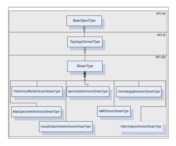
Figure 10 - StreamType Hierarchy
StreamType is a subtype of TopologyElementType.
A Stream may have Parameters. If a Stream has Parameters they appear in an Object called ParameterSet as a flat list of Parameters. Parameters of a Stream are identified by the <ParameterIdentifier> browse name. Parameters of a Stream can be organized in FunctionalGroups identified as <GroupIdentifier> browse name.
StreamType defines seven mandatory FunctionalGroups (see clause 5.2.1.4 for more details):
- Configuration - used to organize Parameters representing the high-level configuration items of the stream, which are expected to be modified by end users.
- Status - used to organize Parameters which describe the general health of the stream.
- AcquistionSettings - used to organize Parameters which describe the conditions of the following acquisition on a stream.
- AcquisitionStatus – used to organize Parameters which describe the status of an ongoing acquisition on a stream.
- AcquisitionData - used to organize all Parameters which represent data retrieved at the end of the data acquisition.
- ChemometricModelSettings - used to organize Parameters which describe/configure the chemometric models used during the data acquisition
- Context - used to organize all Parameters which provide the context for the data acquired through the Stream. Context Parameters are not generally used by the analyser but can be published to uniquely tie acquired data with the controlling process. Examples of context Parameters are: CampaignID, BatchID, LotID, MaterialID, and SampleId.
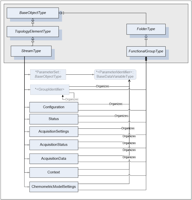
Figure 11 - Stream FunctionalGroups
Table 33 – StreamType Definition
|
Attribute |
Value |
|||||
|
BrowseName |
StreamType |
|||||
|
IsAbstract |
False |
|||||
|
References |
NodeClass |
BrowseName |
DataType |
TypeDefinition |
ModellingRule |
|
|
Subtype of the TopologyElementType defined in [OPC 10000-100]. |
||||||
|
|
|
|
|
|
|
|
|
HasComponent |
Object |
ParameterSet |
|
BaseObjectType |
Mandatory |
|
|
|
|
|
|
|
|
|
|
HasComponent |
Object |
<GroupIdentifier> |
|
FunctionalGroupType |
OptionalPlaceHolder |
|
|
HasComponent |
Object |
Configuration |
|
FunctionalGroupType |
Mandatory |
|
|
HasComponent |
Object |
Status |
|
FunctionalGroupType |
Mandatory |
|
|
HasComponent |
Object |
AcquisitionSettings |
|
FunctionalGroupType |
Mandatory |
|
|
HasComponent |
Object |
AcquisitionStatus |
|
FunctionalGroupType |
Mandatory |
|
|
HasComponent |
Object |
AcquisitionData |
|
FunctionalGroupType |
Mandatory |
|
|
HasComponent |
Object |
ChemometricModelSettings |
|
FunctionalGroupType |
Mandatory |
|
|
HasComponent |
Object |
Context |
|
FunctionalGroupType |
Mandatory |
|
Parameters defined for the StreamType are described in the following tables. The tables correspond to mandatory FunctionalGroups defined for the StreamType. Additional Parameters may be defined for Stream on subtypes of AnalyserDeviceType and associated with those FunctionalGroups.
All Stream Parameters exist as components of the ParameterSet Object defined on that Stream. Each Parameter defined for a Stream shall be accessible through one and only one FunctionalGroup defined on that Stream. Note, that the same Parameter is not instantiated more than once. Both, ParameterSet and a specific FunctionalGroup maintain References to the same instance of the Parameter.
Table 34 describes the Parameters that are organized by the Configuration FunctionalGroup of a Stream.
Table 34 –Stream Configuration Parameters
|
BrowseName |
Description |
VariableType |
Optional/ Mandatory |
|
IsEnabled |
True if this stream maybe used to perform acquisition. This Parameter is mainly used for maintenance. |
DataItemType (DataType=Boolean) |
M |
|
IsForced |
True if this Stream is forced, which means that is the only Stream on this AnalyserChannel that can be used to perform acquisitions. This Parameter is mainly used for maintenance. |
DataItemType (DataType=Boolean) |
O |
Table 35 describes the Parameters that are organized by the Status FunctionalGroup of a Stream. All Parameters organized by this FunctionalGroup shall be read-only.
Table 35 –Stream Status Parameters
|
BrowseName |
Description |
VariableType |
Optional/ Mandatory |
|
DiagnosticStatus |
Stream health status |
(DataType=DeviceHealthEnumeration) |
M |
|
LastCalibrationTime |
Time at which the last successful calibration was run. This is the SourceTimestamp of the main acquisition data of the first acquisition for this calibration. If unknown, it shall be set to DateTime.MinValue. |
DataItemType (DataType=DateTime) |
O |
|
LastValidationTime |
Time at which the last successful validation was run. This is the SourceTimestamp of the main acquisition data of the first acquisition for this validation. If unknown, it shall be set to DateTime.MinValue. |
DataItemType (DataType=DateTime) |
O |
|
LastSampleTime |
Time at which the last sample was acquired. This is the SourceTimestamp of the main acquisition data for this sample acquisition. If unknown, it shall be set to DateTime.MinValue. |
DataItemType (DataType=DateTime) |
M |
|
|
|
|
|
Table 36 describes the Parameters that are organized by the AcquisitionSettings FunctionalGroup of a Stream.
Table 36 - Stream AcquisitionSettings Parameters
|
BrowseName |
Description |
VariableType |
Optional/ Mandatory |
|
TimeBetweenSamples |
Number of milliseconds between two consecutive starts of acquisition. Value 0 means “as fast as possible” |
AnalogItemType (DataType=Duration) |
O |
Table 37 describes the Parameters that are organized by theAcquisitionStatus FunctionalGroup of a Stream. All Parameters organized by this FunctionalGroup shall be read-only.
Table 37 –Stream AcquisitionStatus Parameters
|
BrowseName |
Description |
VariableType |
Optional/ Mandatory |
|
IsActive |
True if this stream is actually running, acquiring data. Only one Stream may be marked as IsActive on a given AnalyserChannel at any given time. |
DataItemType (DataType=Boolean) |
M |
|
ExecutionCycle |
Indicates which acquisition cycle is in progress |
DataItemType (ExecutionCycleEnumeration) |
M |
|
ExecutionCycleSubcode |
Indicates a vendor defined code, which further describes the acquisition cycle. |
MultiStateDiscreteType |
M |
|
Progress |
Indicates the progress of an acquisition (e.g. percentage of completion) |
DataItemType (DataType=Float) |
M |
ExecutionCycle indicates the type of acquisition in progress and it is set in the SelectExecutionCycle state of the AnalyserChannel_OperatingModeExecuteSubStateMachine..
Progress is a float number from 0 to 100 defining the completion of the ongoing acquisition cycle. The granularity of the Progress update is vendor specific. It is set to 0 in the SelectExecutionCycle of the AnalyserChannel_OperatingModeExecuteSubStateMachine.
Table 38 describes the Parameters that are organized by the AcquisitionData FunctionalGroup of a Stream.
Table 38 –Stream AcquisitionData Parameters
|
BrowseName |
Description |
VariableType |
Optional/ Mandatory |
|
AcquisitionCounter |
Simple counter incremented after each Sampling acquisition performed on this Stream; The counter is not incremented for acquisition cycles other than Sampling. It is used to support detection of missing acquisition. Wrap to 0 when it reaches 2147483647. The starting value at power up is vendor specific |
AnalogItemType (DataType=Counter) |
M |
|
AcquisitionResultStatus |
Quality of the acquisition |
DataItemType (AcquisitionResultStatusEnumeration) |
M |
|
<ProcessVariableIdentifier> |
Most commonly, it is a reference to process data produced as a result of applying the chemometric model to ScaledData.. There can be multiple Parameters representing process data and uniquely identified by the <ProcessVariableIdentifier> BrowseName. |
ProcessVariableType |
O |
|
Offset |
The Offset Parameter holds the difference in milliseconds between the start of sample extraction and the start of the analysis. |
AnalogItemType (DataType=Duration) |
O |
|
RawData |
Raw data produced as a result of data acquisition on the Stream (see definition of raw data) |
DataItemType (DataType is defined on a subtype of AnalyserDeviceType) |
O |
|
ScaledData* |
Scaled data produced as a result of data acquisition on the Stream and applying the analyser model. The data type used is analyser dependent. (see definition of scaled data) |
DataItemType (DataType is defined on a subtype of AnalyserDeviceType) |
M |
|
AcquisitionEndTime |
The end time of the AnalyseSample or AnalyseCalibrationSample or AnalyseValidationSample state of the AnalyserChannel_OperatingModeExecuteSubStateMachine state machine. This time should not be used for critical data synchronization but rather for correlation with other external events in the diagnostic context. If unknown, AcquisitionEndTime shall be set to DateTime.MinValue |
DataItemType (DataType=DateTime) |
M |
*Definition of the ScaledData Parameter here is only to indicate that this Parameter must be defined for a Stream on a subtype of an AnalyserDeviceType. Since different analyser classes will produce scaled data of different type as their output, it is impossible to fully define this Parameter at this level. See ScaledData Parameter definition for specific class of analyser. If more than one ScaledData is required, Parameters representing those additional ScaledData shall be called ScaledData1, ScaledData2... ScaledData<n>.
The Offset Parameter holds the difference in milliseconds between the start of sample extraction and the start of the analysis which is the time in millisconds between the WaitForXXXTrigger to ExtractXXXSample transition and the PrepareXXXSample to AnalyseXXXSample transition.
As a general rule, a single Parameter shall not be used to represent different data elements. For example, ScaledData shall be used for the Sample acquisition and another Parameter shall be used to publish the output of the Calibration acquisition. However, in the case where the Validation cycle consists only of acquisition of normal samples, the ScaledData Parameter may be used. A consumer of data from an Analyser Server must be able to correlate values collected from different Parameters. Specifically, it must be possible to associate scaled data with raw data, process data and context data collected during the same acquisition cycle. The data correlation is based on time-stamps used during data collection. SourceTimestamp shall be the time when the sampling system starts extracting the sample, defined by the start of the ExtractSample or ExtractCalibrationSample or ExtractValidationSample state of the AnalyserChannel_OperatingModeExecuteSubStateMachine. The difference between the SourceTimestamp and the time when the sample is analysed, is reflected in the Offset Parameter defines in AcquisitionData.
To simplify integration with historians, Parameters in the AcquisitionData FunctionalGroup shall be updated once per acquisition cycle.
Time-stamp management rules:
- The time-stamp of the analyser main data (RawData, ScaledData) shall be the start time of the ExtractSample or ExtractCalibrationSample or ExtractValidationSample state of the AnalyserChannel_OperatingModeExecuteSubStateMachine.
- All values derived from acquired data shall have the same SourceTimestamp as the acquired data. For example RawData, ScaledData, AcquisitionEndTime shall have the same SourceTimestamp.
- If a derived value combines acquired data from different data sources, the time-stamp of the “main” data shall be used. Which data source is the main data, is vendor specific, but shall be consistent and documented.
- If a derived value combines acquired data from different AnalyserChannels, the time-stamp of the “main” AnalyserChannel shall be used. Which AnalyserChannel is the main AnalyserChannel, is vendor specific, but shall be consistent and documented.
- The last item updated after the end of acquisition (PublishResults state) is AcquisitionResultStatus which is set to GOOD_1, BAD_2, UNKNOWN_3 or PARITAL_4. This implies that all items that are part of this acquisition shall have been updated; this includes items from AcquisitionData and Context FunctionalGroup.
- The OPC UA SourceTimestamp is always in UTC time.
For details on SourceTimestamp elements of a DataValue see [OPC 10000-4].
When the analyser is working in a standalone mode i.e. it is not driven by a DCS or other external control system, the analyser should publish the Context Parameters using data provided by user or other system entry system like a barcode reader.
Table 39 describes the Parameters that are organized by the Context FunctionalGroup of a Stream.
Table 39 –Stream Context Parameters
|
BrowseName |
Description |
VariableType |
Optional/ Mandatory |
|
CampaignId |
Defines the current campaign |
DataItemType (DataType=String) |
O |
|
BatchId |
Defines the current batch |
DataItemType (DataType=String) |
O |
|
SubBatchId |
Defines the current sub-batch |
DataItemType (DataType=String) |
O |
|
LotId |
Defines the current lot |
DataItemType (DataType=String) |
O |
|
MaterialId |
Defines the current material |
DataItemType (DataType=String) |
O |
|
Process |
Current Process name |
DataItemType (DataType=String) |
O |
|
Unit |
Current Unit name |
DataItemType (DataType=String) |
O |
|
Operation |
Current Operation name |
DataItemType (DataType=String) |
O |
|
Phase |
Current Phase name |
DataItemType (DataType=String) |
O |
|
UserId |
Login name of the user who is logged on at the device console. If no Operator logon, “System” shall be assigned to UserId. |
DataItemType (DataType=String) |
O |
|
SampleId |
Identifier for the sample |
DataItemType (DataType=String) |
O |
Table 40 shows Parameters that will be organized by the ChemometricModelSettings FunctionalGroup.
Table 40 – Stream ChemometricModelSettings Parameters
|
BrowseName |
Description |
VariableType |
Optional/ Mandatory |
|
<ChemometricModelId> |
Chemometric Model used to convert scaled data into process data |
ChemometricModelType (DataType=Byte) |
O |
AccessorySlotType defines the general structure of an AccessorySlot Object. Figure 12 shows the detailed composition of AccessorySlotType. It is formally defined in Table 41.
The SupportedTypes folder is used to maintain the set of (sub-types of) AccessoryTypes supported by that accessory slot.
AccessorySlotType states are exposed through the AccessorySlotStateMachine Object of type AccessorySlotStateMachineType. For details on AccessorySlotStateMachineType see clause 5.3.5.
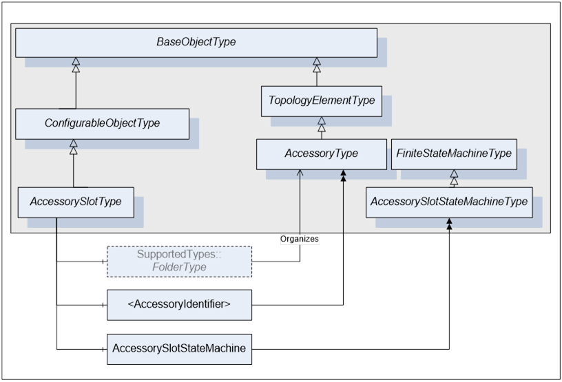
Figure 12 - AccessorySlotType Components
Table 41 – AccessorySlotType Definition
|
Attribute |
Value |
|||||
|
BrowseName |
AccessorySlotType |
|||||
|
IsAbstract |
False |
|||||
|
References |
NodeClass |
BrowseName |
DataType |
TypeDefinition |
ModellingRule |
|
|
Subtype of the ConfigurableObjectType defined in [OPC 10000-100] |
||||||
|
HasProperty |
Variable |
IsHotSwappable |
Boolean |
PropertyType |
Mandatory |
|
|
HasProperty |
Variable |
IsEnabled |
Boolean |
PropertyType |
Mandatory |
|
|
HasComponent |
Object |
AccessorySlotStateMachine |
|
AccessorySlotStateMachineType |
Mandatory |
|
|
HasComponent |
Object |
<AccessoryIdentifier> |
|
AccessoryType |
OptionalPlaceHolder |
|
AccessorySlotType inherits from the ConfigurableObjectType. SupportedTypes contain References to supported AccessoryTypes. .
IsHotSwappable Property is True if an accessory can be inserted in the accessory slot while it is powered.
IsEnabled Property is True if this accessory slot is capable of accepting an accessory in it.
AccessorySlotStateMachine describes internal states of the accessory slot.
<AccessoryIdentifier> represents the accessory currently installed in the accessory slot.
The term AccessorySlot refers to an instance of AccessorySlotType ObjectType as defined in Table 41.
AccessorySlotType can be instantiated as components of an AnalyserDevice Object or any of its subtypes.
Optionally AccessorySlotAccessorySlotType can be instantiated as components of the AnalyserChannel Objects.
This ObjectType defines the structure of an Accessory Object. Figure 13 shows the AccessoryType components. It is formally defined in Table 42.
AccessoryType is a subtype of TopologyElementType.
An Accessory may have Parameters. If an Accessory has Parameters they appear in an Object called ParameterSet as a flat list of Parameters. Parameters of an Accessory are identified by <ParameterIdentifier> Parameters of an Accessory can be organized in FunctionalGroups identified as <GroupIdentifier>. An Accessory has at least three FunctionalGroups that expose its Parameters in an organized fashion. The three mandatory FunctionalGroups are:
- Configuration - used to organize Parameters representing the high-level configuration items of the accessory, which are expected to be modified by end users.
- Status - used to organize Parameters which describe the general health of the a ccessory.
- FactorySettings - used to organize Parameters which describe the factory settings of the accessory and are not expected to be modified by end users.
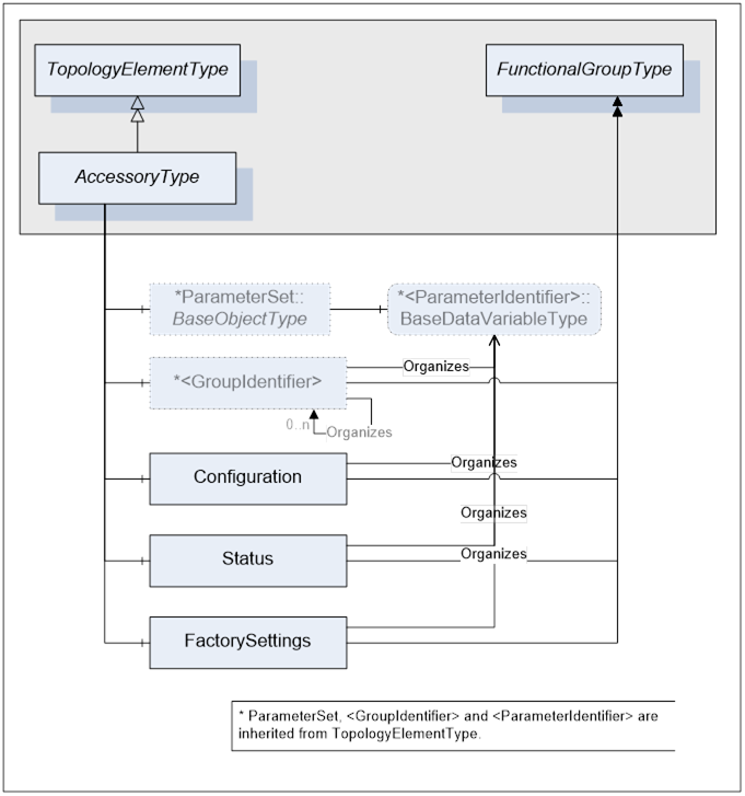
Table 42 – AccessoryType Definition
|
Attribute |
Value |
|||||
|
BrowseName |
AccessoryType |
|||||
|
IsAbstract |
False |
|||||
|
References |
NodeClass |
BrowseName |
DataType |
TypeDefinition |
ModellingRule |
|
|
Subtype of the TopologyElementTypee defined in [OPC 10000-100] |
||||||
|
HasComponent |
Object |
Configuration |
|
FunctionalGroupType |
Mandatory |
|
|
HasComponent |
Object |
Status |
|
FunctionalGroupType |
Mandatory |
|
|
HasComponent |
Object |
FactorySettings |
|
FunctionalGroupType |
Mandatory |
|
|
|
|
|
|
|
|
|
|
HasComponent |
Variable |
IsHotSwappable |
Boolean |
PropertyType |
Mandatory |
|
|
HasComponent |
Variable |
IsReady |
Boolean |
PropertyType |
Mandatory |
|
IsHotSwappable Property is True if this accessory can be inserted in an accessory slot while it is powered. Its value may only be True when it is in Installed state. It shall be False in all other states.
IsReady Property is True if this accessory is ready to be used. Its value may only be True when it is in Installed state, It shall be False in all other states.
The term Accessory refers to an instance of AccessoryType ObjectType as defined in Table 42.
Accessory Objects can be instantiated as components of an AccessorySlot Object.
This specification defines three sub-types of AccesoryType: DetectorType, SmartSamplingSystemType and SourceType.
Table 43 describes a detector Accessory which is capable of producing raw data for an analyser.
|
Attribute |
Value |
|||||
|
BrowseName |
DetectorType |
|||||
|
IsAbstract |
True |
|||||
|
References |
NodeClass |
BrowseName |
DataType |
TypeDefinition |
ModellingRule |
|
|
Subtype of the AccessoryType defined in 5.2.5. |
||||||
|
|
|
|
|
|
|
|
Table 44 describes an intelligent sampling system Accessory used to extract samples from the process monitored by an analyser. It may also be used for non-intrusive device like ATR. It is “smart” in the sense that it provides interaction through configuration and/or status compared to passive sampling systems that provide no status or control capabilities.
Table 44 - SmartSamplingSystemType
|
Attribute |
Value |
|||||
|
BrowseName |
SmartSamplingSystemType |
|||||
|
IsAbstract |
True |
|||||
|
References |
NodeClass |
BrowseName |
DataType |
TypeDefinition |
ModellingRule |
|
|
Subtype of the AccessoryType defined in 5.2.5. |
||||||
|
|
|
|
|
|
|
|
Table 45 describes an Accessory used by spectrometers (infrared, visible, UV etc.) with internal source that illuminate the sample.
|
Attribute |
Value |
|||||
|
BrowseName |
SourceType |
|||||
|
IsAbstract |
True |
|||||
|
References |
NodeClass |
BrowseName |
DataType |
TypeDefinition |
ModellingRule |
|
|
Subtype of the AccessoryType defined in 5.2.5. |
||||||
|
|
|
|
|
|
|
|
Table 46 - SpectrometerDeviceType
|
Attribute |
Value |
|||||
|
BrowseName |
SpectrometerDeviceType |
|||||
|
IsAbstract |
False |
|||||
|
References |
NodeClass |
BrowseName |
DataType |
TypeDefinition |
ModellingRule |
|
|
Subtype of the AnalyserDeviceType defined in 5.2.1.1 |
||||||
|
|
|
|
|
|||
The term SpectrometerDevice refers to an instance of SpectrometerDeviceType ObjectType as defined in Table 46
All SpectrometerDevice Objects have Attributes and Properties that they inherit from the AnalyserDeviceType.
Table 47 describes the Parameters that are organized by the FactorySettings FunctionalGroup of a SpectrometerDeviceType.
Table 47 – SpectrometerDeviceType FactorySettings Parameters
|
BrowseName |
Description |
VariableType |
Optional/ Mandatory |
|
SpectralRange |
All spectral ranges that can be covered by this analyser. Vendors are expected to use a subtype of DataItemType to provide engineering units through the standard Property EngineeringUnits of type EUInformation. Typical units will be cm-1 and µm. |
DataItemType (DataType=Range[] ) |
O |
In general, a spectrometer covers one spectral range, but some spectrometers may cover more than one. In case of spectrometers based on a filter wheel, each entry in the array is the band of one of the filters. This is why an array of Range is used as the data type for this Parameter.
SpectrometerDeviceStreamType defines seven mandatory FunctionalGroups described in5.2.3.1: Configuration, Status, AcquistionSettings, AcquisitionStatus, AcquisitionData, ChemometricModelSettings, and Context.
Table 48 describes the Parameters that are organized by the Configuration FunctionalGroup of a SpectrometerDeviceStreamType.
Table 48 – SpectrometerDeviceStreamType Configuration Parameters
|
BrowseName |
Description |
VariableType |
Optional/ Mandatory |
|
ActiveBackground |
Background spectrum used for the evaluation of the absorbance. In the case of spectrometer like diode array that requires black and white background, this is the white background. |
YArrayItemType (DataType=Float)
|
M |
|
ActiveBackground1 |
Background spectrum used for the evaluation of the absorbance. In the case of spectrometer like diode array that requires black and white background, this is the black background and the Parameter is mandatory. |
YArrayItemType (DataType=Float)
|
O |
If more then one background spectrum is required, Parameters representing those additional background spectra shall be called ActiveBackground1, ActiveBackground2,...,ActiveBackground<n> and the same ModellingRules as for ActiveBackground Parameter shall apply.
Table 49 describes the Parameters that are organized by the AcquisitionSettings FunctionalGroup of a SpectrometerDeviceStreamType.
Table 49 – SpectrometerDeviceStreamType AcquisitionSettings Parameters
|
BrowseName |
Description |
VariableType |
Optional/ Mandatory |
|
SpectralRange |
Spectral range of this acquisition. Vendors are expected to use a subtype of DataItemType to provide engineering units through the standard Property EngineeringUnits of type EUInformation. Typical units will be cm-1 and µm. |
O |
|
|
Resolution |
Acquisition resolution May be an enum or Float |
DataItemType
|
O |
|
RequestedNumberOfScans |
Number of scans to be averaged This Parameter is often referred to as ObservationTime |
AnalogItemType (DataType=Int32) |
O |
|
Gain |
Detector gain May be an enum or Float |
DataItemType
|
O |
|
TransmittanceCutoff |
Transmittance clipping limits |
DataItemType (DataType=Range) |
O |
|
AbsorbanceCutoff |
Absorbance clipping limits |
DataItemType (DataType=Range) |
O |
Many of the Parameters in the AcquisitionSettings FunctionalGroup are used for sample acquisition. Calibration and validation may or may not use the same value. It is up to the vendor to select his approach: share Parameters or use different ones. Nested FunctionalGroup may also be used to organize different set of Parameters.
Table 50 describes the Parameters that are organized by the AcquisitionStatus FunctionalGroup of a SpectrometerDeviceStreamType. All Parameters organized by this FunctionalGroup shall be read-only.
Table 50 – SpectrometerDeviceStreamType AcquisitionStatus Parameters
|
BrowseName |
Description |
VariableType |
RW |
Optional/ Mandatory |
|
NumberOfScansDone |
Actual number of scans completed |
AnalogItemType (DataType=Int32) |
RO |
O |
Table 51 describes the Parameters that are organized by the AcquisitionData FunctionalGroup of a SpectrometerDeviceStreamType.
Table 51 – SpectrometerDeviceStreamType AcquisitionData Parameters
|
BrowseName |
Description |
VariableType |
RW |
Optional/ Mandatory |
|
RawData |
Raw spectrum in arbitrary units |
YArrayItemType (DataType=Float) |
RO |
O |
|
ScaledData* |
Absorbance |
YArrayItemType (DataType=Float) |
RO |
M |
|
TotalNumberOfScansDone |
Total number of scans done at the end of acquisition. |
AnalogItemType (DataType=Int32) |
RO |
M |
|
BackgroundAcquisitionTime |
Time stamp of the background used for this acquisition. If more then one background spectrum is required, the time of ActiveBackground shall be used. Background is acquired during calibration acquisition cycle. |
DataItemType (DataType=DateTime) |
RO |
M |
|
PendingBackground |
Last acquired Background spectrum. This Background is not automatically used for evaluation of ScaledData (Absorbance) - see ActiveBackground Parameter. In the case of spectrometer like diode array that requires black and white background, this is the white background. |
YArrayItemType (DataType=Float)
|
RO |
M |
|
PendingBackground1 |
Last acquired Background spectrum. This Background is not automatically used for evaluation of ScaledData (Absorbance) - see ActiveBackground Parameter. In the case of spectrometer like diode array that requires black and white background, this is the black background and the Parameter is mandatory |
YArrayItemType (DataType=Float)
|
RO |
O |
If more then one background spectrum is required, Parameters representing those additional background spectra shall be called PendingBackground1, PendingBackground2,...,PendingBackground<n> and the same ModellingRules as for PendingBackground Parameter shall apply.
* ScaledData Parameter at this level represents the same Parameter that was defined on StreamType. Since different types of analysers may represent ScaledData differently, it was impossible to declare the VariableType of this Parameter at the StreamType level. It is possible here because the scope of the definition is limited to SpectrometerDeviceType. Devices of this type use YArrayItemType to represent ScaledData.
Table 52 - MassSpectrometerDeviceType
|
Attribute |
Value |
|||||
|
BrowseName |
MassSpectrometerDeviceType |
|||||
|
IsAbstract |
False |
|||||
|
References |
NodeClass |
BrowseName |
DataType |
TypeDefinition |
ModellingRule |
|
|
Subtype of the AnalyserDeviceType defined in 5.2.1.1 |
||||||
|
|
|
|
|
|
|
|
The term MassSpectrometerDevice refers to an instance of MassSpectrometerDeviceType ObjectType as defined in Table 52.
There is no specific Parameter in MassSpectrometerDeviceStreamType.
Particle size can be determined by light scattering (e.g. Focus Beam Reflectance Measurement, Laser Diffraction) or other Methods. This type of analyser can be used to implement particle monitoring technique for in-line real-time measurement of particle size. A wide range of industrial process control applications are therefore possible such as the online control of crystallizers.
ParticleSizeMonitorDeviceType defines the general structure of a ParticleSizeMonitorDevice Object.
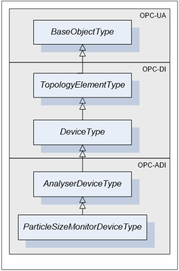
Figure 14 - ParticleSizeMonitorDeviceType
ParticleSizeMonitorDeviceType is a subtype of AnalyserDeviceType.
Table 53 - ParticleSizeMonitorDeviceType
|
Attribute |
Value |
|||||
|
BrowseName |
ParticleSizeMonitorDeviceType |
|||||
|
IsAbstract |
False |
|||||
|
References |
NodeClass |
BrowseName |
DataType |
TypeDefinition |
ModellingRule |
|
|
Subtype of the AnalyserDeviceType defined in 5.2.1.1 |
||||||
|
|
|
|
|
|
|
|
The term ParticleSizeMonitorDevice refers to an instance of ParticleSizeMonitorDeviceType ObjectType as defined in Table 53.
All ParticleSizeMonitorDevice have Attributes and Properties that they inherit from the AnalyserDeviceType.
ParticleSizeMonitorDeviceStreamType defines seven mandatory FunctionalGroups described in5.2.3.1: Configuration, Status, AcquistionSettings, AcquisitionStatus, AcquisitionData, ChemometricModelSettings, Context. Parameters exposed by an Stream of a ParticleSizeMonitorDevice should be organized by those FunctionalGroups based on their meaning.
Table 54 describes the Parameters that are organized by the AcquisitionData FunctionalGroup of a ParticleSizeMonitorDeviceStreamType.
Table 54 – ParticleSizeMonitorDeviceStreamType AcquisitionData Parameters
|
BrowseName |
Description |
VariableType |
Optional/ Mandatory |
|
Background |
Array describing the measured background on detector(s.) |
YArrayItemType (DataType=Float) |
O |
|
RawData |
Array describing the measured raw data on detector(s) in arbitrary units. |
YArrayItemType (DataType=Float) |
O |
|
ScaledData |
Array describing the corrected measured data detector(s), for example after background subtraction |
YArrayItemType (DataType=Float) |
M |
|
SizeDistribution |
Returns the Particle Size Distribution |
YArrayItemType (DataType=Float) |
M |
|
BackgroundAcquisitionTime |
Time stamp of the background used for this acquisition |
DataItemType (DataType=DateTime) |
M |
Table 55 - AcousticSpectrometerDeviceType
|
Attribute |
Value |
||||||
|
BrowseName |
AcousticSpectrometerDeviceType |
||||||
|
IsAbstract |
False |
||||||
|
References |
NodeClass |
BrowseName |
DataType |
TypeDefinition |
ModellingRule |
||
|
Subtype of the AnalyserDeviceType defined in 5.2.1.1 |
|||||||
|
|
|
|
|
|
|
||
The term AcousticSpectrometerDevice refers to an instance of AcousticSpectrometerDeviceType ObjectType as defined in Table 55.
There is no specific Parameter in AcousticSpectrometerDeviceStreamType.
Chromatograph retrieves the concentration of chemical components by using a set of separation columns that separate each molecule based on the time it takes to go through a given column path.
ChromatographrDeviceType defines the general structure of a ChromatographDevice Object
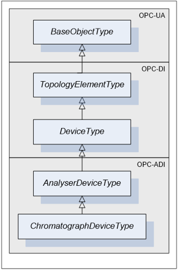
Figure 15 - ChromatographDeviceType
ChromatographDeviceType is a subtype of AnalyserDeviceType
Table 56 - ChromatographDeviceType
|
Attribute |
Value |
|||||
|
BrowseName |
ChromatographDeviceType |
|||||
|
IsAbstract |
False |
|||||
|
References |
NodeClass |
BrowseName |
DataType |
TypeDefinition |
ModellingRule |
|
|
Subtype of the AnalyserDeviceType defined in 5.2.1.1 |
||||||
|
|
|
|
|
|
|
|
The term ChromatographDevice refers to an instance of ChromatographType ObjectType as defined in Table 56.
All ChromatographDevices have Attributes and Properties that they inherit from the AnalyserDeviceType.
StreamType defines seven mandatory FunctionalGroups described in5.2.3.1: Configuration, Status, AcquistionSettings, AcquisitionStatus, AcquisitionData, ChemometricModelSettings, and Context. The following tables describe Parameters defined on the Stream of a ChromatographDevice.
Table 40 describes the Parameters that are organized by the AcquisitionData FunctionalGroup of a ChromatographDeviceStreamType.
Table 57 – ChromatographDeviceStreamType AcquisitionData Parameters
|
BrowseName |
Description |
VariableType |
Optional/ Mandatory |
|
ScaledData* |
Chromatogram |
YArrayItemType [] (DataType=Float) |
M |
|
ComponentX |
Component analysed by a chromatograph |
EngineeringValueType (DataType=Float) |
M |
* ScaledData Parameter at this level represents the same Parameter that was defined on StreamType. Since different types of analysers may represent ScaledData differently, it was impossible to declare the VariableType of this Parameter at the StreamType level. It is possible here because the scope of the definition is limited to ChromatographDeviceType. Devices of this type use array of YArrayItemType to represent ScaledData.
The YArrayItem describing the chromatogram has the following behaviors:
- Because the Chromatograph may collect many chromatograms simultaneously, ScaledData is an array of YArrayItem.
- X axis is the time in seconds since the injection time, which is the start of the ExtractSample or ExtractCalibrationSample or ExtractValidationSample state of the AnalyserChannel_OperatingModeExecuteSubStateMachine.
- Y axis unit is vendor specific, usually volts at the detector output.
- To reduce data bandwidth, the X axis may not be continuous i.e. when there is no peak, no data is produced. This implies that the xAxisDefinition.axisSteps shall be provided.
- The xAxisDefinition.axisSteps of each chromatogram may be different because the peak positions are different from column to column.
The Chromatograph Component values are mapped using EngineeringValueType and they are placed under the appropriate Stream in the AcquisitionData FunctionalGroup. Annex B provides an example of its sub-elements.
Table 58 describes a gas chromatograph oven Accessory which maintains its set of valves, columns and detectors at the temperature defined by the chromatographic application.
|
Attribute |
Value |
|||||
|
BrowseName |
GCOvenType |
|||||
|
IsAbstract |
True |
|||||
|
References |
NodeClass |
BrowseName |
DataType |
TypeDefinition |
ModellingRule |
|
|
Subtype of the AccessoryType defined in 5.2.5. |
||||||
|
|
|
|
|
|
|
|
|
Attribute |
Value |
|||||
|
BrowseName |
NMRDeviceType |
|||||
|
IsAbstract |
False |
|||||
|
References |
NodeClass |
BrowseName |
DataType |
TypeDefinition |
ModellingRule |
|
|
Subtype of the AnalyserDeviceType defined in 5.2.1.1 |
||||||
|
|
|
|
|
|
|
|
The term NMRDevice refers to an instance of NMRDeviceType ObjectType as defined in Table 59.
There is no specific Parameter in NMRStreamType.