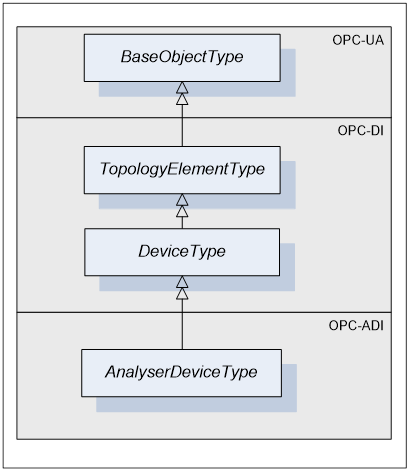
AnalyserDeviceType defines the general structure of an AnalyserDevice Object. Figure 3, Figure 4 and Figure 5 show the inheritance hierarchy and detailed composition of AnalyserDeviceType. It is formally defined in Table 1.
AnalyserDeviceType is a subtype of DeviceType [OPC 10000-100] and as such can have Parameters which are kept in an Object called ParameterSet. Parameters represented by <ParameterIdentifier > and their list called ParameterSet are inherited from DeviceType.
TopologyElementType [OPC 10000-100] introduced a component called MethodSet, which can be used to organize Methods exposed to the Client. AnalyserDeviceType takes advantage of that inherited component and groups all of its Methods under MethodSet.
DeviceType also introduces FunctionalGroups identified by <GroupIdentifier> that expose its Parameters in an organized fashion reflecting the structure of the device. AnalyserDeviceType can have any number of FunctionalGroups.
AnalyserDeviceType defines three mandatory FunctionalGroups:
- Configuration - used to organize Parameters representing the high-level configuration items of the analyser, which are expected to be modified by end users.
- Status - used to organize Parameters which describe the general health of the analyser.
- FactorySettings - used to organize Parameters, which describe the factory settings of the analyser that are not expected to be modified by end users.
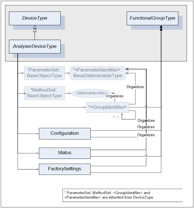
Figure 4 – AnalyserDeviceType Components
The AnalyserDevice Object that represents an analyser has one or more AnalyserChannels. AnalyserChannel is described in clause 5.2.2. The AnalyserChannel Node instances are identified by <ChannelIndentifier> browse name.
AnalyserDevice Object has zero or more Objects of type AccessorySlotType and identified by <AccessorySlotIdentifier>. AccessorySlotType is described in clause5.2.4. AccessorySlot Objects represent physical locations on the analyser where the analytical accessory can be mounted. Accessories currently mounted on the analyser device as well as the supported accessories for the accessory slot are represented as components of the AccessorySlot Object. For details refer to clause 5.2.3.
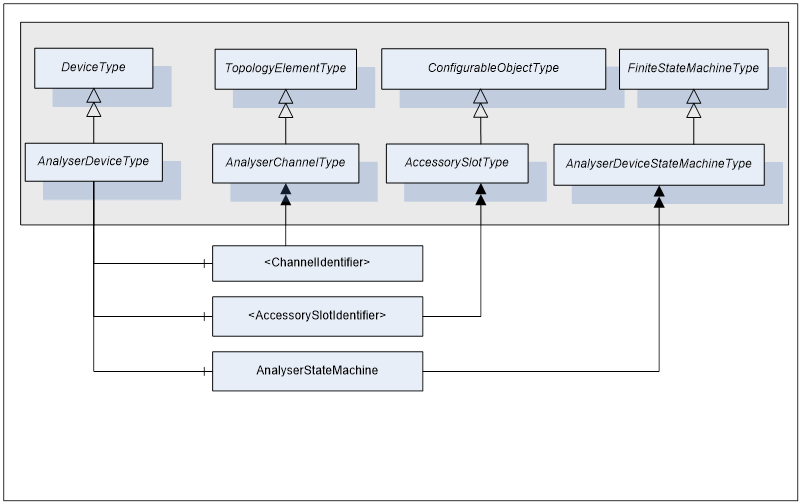
Figure 5 - AnalyserDeviceType Components cont.
AnalyserDeviceType does not expose any mandatory Parameters to report or manipulate the state of an analyser device. Instead, AnalyserDevice states are exposed through the AnalyserStateMachine component of type AnalyserDeviceStateMachineType. For details on AnalyserDeviceStateMachineType see clause 5.3.2.
Table 1 - AnalyserDeviceType Definition
|
Attribute |
Value |
|||||
|
BrowseName |
AnalyserDeviceType |
|||||
|
IsAbstract |
True |
|||||
|
References |
NodeClass |
BrowseName |
DataType |
TypeDefinition |
ModellingRule |
|
|
Subtype of the DeviceType defined in [OPC 10000-100] |
||||||
|
HasSubtype |
ObjectType |
SpectrometerDeviceType |
Defined in Clause 5.2.6.1 |
|||
|
HasSubtype |
ObjectType |
ParticleSizeMonitorDeviceType |
Defined in Clause 5.2.8.1 |
|||
|
HasSubtype |
ObjectType |
AcousticSpectrometerDeviceType |
Defined in Clause 5.2.9.1 |
|||
|
HasSubtype |
ObjectType |
MassSpectrometerDeviceType |
Defined in Clause 5.2.7.1 |
|||
|
HasSubtype |
ObjectType |
ChromatographDeviceType |
Defined in Clause 5.2.10.1 |
|||
|
HasSubtype |
ObjectType |
NMRDeviceType |
Defined in Clause 5.2.11.1 |
|||
|
|
|
|
|
|||
|
HasComponent |
Object |
Configuration |
|
FunctionalGroupType |
Mandatory |
|
|
HasComponent |
Object |
Status |
|
FunctionalGroupType |
Mandatory |
|
|
HasComponent |
Object |
FactorySettings |
|
FunctionalGroupType |
Mandatory |
|
|
HasComponent |
Object |
<ChannelIdentifier> |
|
AnalyserChannelType |
OptionalPlaceHolder |
|
|
HasComponent |
Object |
<AccessorySlotIdentifier> |
|
AccessorySlotType |
OptionalPlaceHolder |
|
|
HasComponent |
Object |
AnalyserStateMachine |
|
AnalyserDeviceStateMachineType |
Mandatory |
|
|
|
|
|
|
|
|
|
|
AnalyserDeviceType.MethodSet |
||||||
|
HasComponent |
Method |
GetConfiguration |
|
|
Mandatory |
|
|
HasComponent |
Method |
SetConfiguration |
|
|
Mandatory |
|
|
HasComponent |
Method |
GetConfigDataDigest |
|
|
Mandatory |
|
|
HasComponent |
Method |
CompareConfigDataDigest |
|
|
Mandatory |
|
|
HasComponent |
Method |
ResetAllChannels |
|
|
Mandatory |
|
|
HasComponent |
Method |
StartAllChannels |
|
|
Mandatory |
|
|
HasComponent |
Method |
StopAllChannels |
|
|
Mandatory |
|
|
HasComponent |
Method |
AbortAllChannels |
|
|
Mandatory |
|
|
HasComponent |
Method |
GotoOperating |
|
|
Mandatory |
|
|
HasComponent |
Method |
GotoMaintenance |
|
|
Mandatory |
|
AnalyserDeviceType is a subtype of DeviceType defined in [OPC 10000-100] and as such it inherits DeviceType’s characteristics. For a complete definition of the DeviceType see [OPC 10000-100].
The AnalyserDeviceType ObjectType is abstract. There will be no instances of an AnalyserDeviceType itself, but there will be instances of sub-types of this type. In this specification, the term AnalyserDevice generically refers to an instance of any ObjectType derived from the AnalyserDeviceType ObjectType.
All AnalyserDevices have Attributes and Properties that they inherit from the DeviceType. For those elements, the same rules as defined for Device Objects in [OPC 10000-100] apply.
The sub types of the AnalyserDeviceType are illustrated in Figure 6. Each of these sub type may be further sub typed.
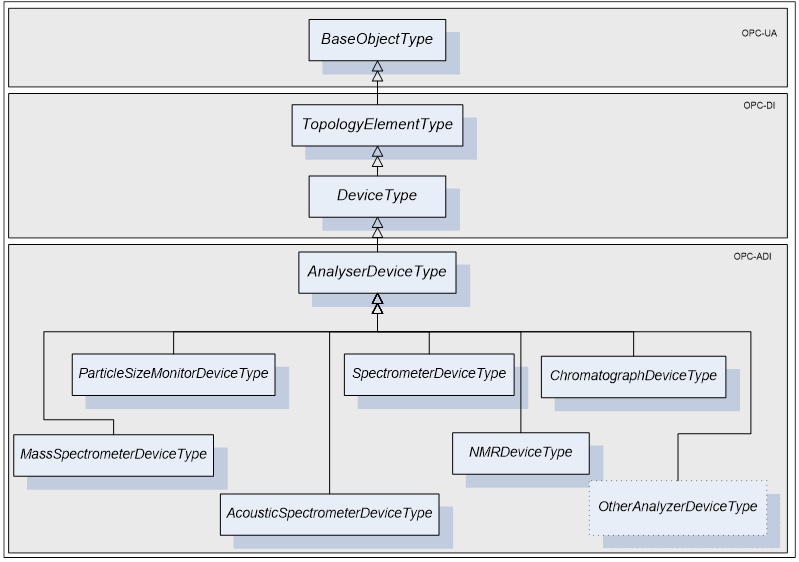
Figure 6 - AnalyserDeviceType Hierarchy
The AnalyserDeviceType is derived from the DeviceType as an Abstract type. It is sub-typed for each one of the analyser classes. Six sub-types are introduced:
Table 2 –AnalyserDeviceType Sub-type definition
|
AnalyserDeviceType |
Description |
|
SpectrometerDeviceType |
A light spectrometer is an optical instrument used to measure Properties of light over a specific portion of the electromagnetic spectrum (IR/NIR/VIS/UV), typically used in spectroscopic analysis to identify chemical composition of sample materials. The use of analytical techniques to determine process control parameters from spectra allows a wide range of industrial applications. This type covers FTIR, diode array, etc. |
|
AcousticSpectrometerDeviceType |
An acoustic spectrometer uses sound wave emission and advanced pattern recognition software to predict the physical Properties of powders and particulates. This type of analyser uses high frequency sounds emitted by all physical and chemical processes (particle impact, turbulent gas flow, gas evolution, fermentation, cavitation and multiphase flow). It is a non-invasive technique which is responding to dynamic event making it suitable for process control. |
|
MassSpectrometerDeviceType |
A mass spectrometer is an analytical instrument used to measure the mass-to-charge ratio of ions. It is most generally used to find the composition of a physical sample by generating a mass spectrum representing the masses of sample components. A wide range of industrial process control applications are therefore possible, such as the online control of solvent drying. |
|
ParticleSizeMonitorDeviceType |
Particle size can be determined by light scattering (e.g. Focus Beam Reflectance Measurement) or other Methods. This type of analyser can be used to implement particle monitoring technique for in-line real-time measurement of particle size. A wide range of industrial process control applications are therefore possible such as the online control of crystallizers |
|
ChromatographDeviceType |
Chromatography is the collective term for a family of techniques for the separation of mixtures. It involves passing a mixture dissolved in a "mobile phase" through a stationary phase, which separates the analyte to be measured from other molecules in the mixture and allows it to be isolated. Chromatography may be preparative or analytical. Preparative chromatography seeks to separate the components of a mixture for further use (and is thus a form of purification). Analytical chromatography normally operates with smaller amounts of material and seeks to measure the relative proportions of analytes in a mixture. The two are not mutually exclusive |
|
NMRDeviceType |
Nuclear Magnetic Resonance spectrometers |
|
|
|
Parameters defined for the AnalyserDeviceType are described in the following tables. The tables correspond to mandatory FunctionalGroups defined for the AnalyserDeviceType. Additional Parameters may be defined on subtypes of AnalyserDeviceType and associated with those FunctionalGroups.
All AnalyserDevice Parameters exist as components of ParameterSet Object defined on that AnalyserDevice through inheritance from DeviceType. Each Parameter defined for an AnalyserDevice shall be accessible through one or more FunctionalGroup defined on that AnalyserDevice. Note, that the same Parameter is not instantiated more than once. Both, ParameterSet and a specific FunctionalGroup maintain References to the same instance of the Parameter.
Table 3 shows Parameters that will be organized by the Configuration FunctionalGroup.
Table 3 – AnalyserDevice Configuration Parameters
|
BrowseName |
Description |
VariableType |
Optional/ Mandatory |
|
ConfigData |
Optional representation of the AnalyserDevice configuration |
FileType
|
O |
|
|
|
|
|
ConfigData is an optional representation of the AnalyserDevice configuration. When it is present, it may be used to read and write the AnalyserDevice configuration in chunks. The main purpose of this element is to provide a way to read and write configuration that are larger than the maximum size of the OPC UA message. Reading and writing configuration through this object are subject to the same state machine constraints as GetConfiguration and SetConfiguration.
To maintain configuration consistency, the server must grant read and write access to one and only one user at any given time.
The steps to update the configuration through the ConfigData object are:
- When SetConfiguration is allowed based on the state machine states, a single user may cal “open” the ConfigData. If an “Open” is attempted when not permitted, the server shall return “Bad_InvalidState”.
- The user updates the configuration by calling repeatitively and in increasing order “write” method on ConfigData. If the “Write” are not sequential, the server shall return “Bad_InvalidArgument”.
- When the whole configuration has been written, the user calls “close” method on the ConfigData.
- The server is responsible to verify the configuration. If an error occurs during the verification, the server shall return “Bad_InvalidArgument” on the “Close”. In case of error, the previous configuration is restored.
- The server commits the new configuration. . If an error occurs during the commit, the server shall return “Bad_InvalidArgument” on the “Close”. In case of error, the previous configuration is restored.
Table 4 shows Parameters that will be organized by the Status FunctionalGroup. All Parameters organized by this FunctionalGroup shall be read-only.
Table 4 – AnalyserDevice Status Parameters
|
BrowseName |
Description |
VariableType |
Optional/ Mandatory |
|
DiagnosticStatus |
General health status of the analyser |
DataItemType DataType=DeviceHealthEnumeration
|
M |
|
|
|
|
|
The DiagnosticStatus Parameter reflects the general health of analyser. It is defined as a Variable of DataItemType type and its possible values are defined by [OPC 10000-100] enumerationDeviceHealthEnumeration. Its value must be the same as DeviceType.DeviceHealth Property.
Table 5 shows Parameters that will be organized by the FactorySettings FunctionalGroup component of the AnalyserDeviceType.
Table 5 – AnalyserDevice FactorySettings Parameters
|
BrowseName |
Description |
VariableType |
Optional/ Mandatory |
|
|
|
|
|
The SerialNumber, Manufacturer, Model, DeviceManual, DeviceRevision, SoftwareRevision and the HardwareRevision Properties are defined on DeviceType and as such available on AnalyserDeviceType. As a general rule, they are read-only properties. However, they can be updated to reflect changes made to the analyser configuration e.g. upgrading the firmware.
DeviceRevision Property will be used to indicate an overall change in the analyser. It is mandatory and shall be updated automatically or manually each time the analyser configuration is altered. It is the customer’s QA responsibility to determine if this particular change affects the validation of the analyser.
The RevisionCounter Property is an incremental counter indicating the number of times the semi-static data within the AnalyserDevice has been modified.
If the analytical device represented by an AnalyserDevice Object is unable to publish a value for a mandatory Parameter defined in Table 5, the Analyser Server should provide a way to manually enter that value.
All Methods defined for AnalyserDeviceType and its state machines are grouped under the MethodSet component inherited from DeviceType [OPC 10000-100].
AnalyserDeviceType defines a Method called GetConfiguration, which is used to read the complete configuration of the AnalyserDevice and all of its components (AnalyserChannel, Accessory, AccessorySlot etc.) from the Analyser Server. The configuration is a proprietary structure defined by the analyser vendor, and is represented as a ByteString.
AnalyserDeviceType defines a Method called SetConfiguration, which is used to write the complete configuration of the AnalyserDevice and all of its components to the Analyser Server. This Method can be executed only when all of the AnalyserChannels are in a Stopped state or in a Maintenance state (see 5.3.4.3). An attempt to call it while in any other state results in a failure of the Method call.
When the SetConfiguration Method is executed, it automatically causes a transition of all AnalyserChannels in a Stopped state to the Resetting state and the new configuration becomes active. The configuration is a structure provided by the analyser vendor, and represented as a ByteString.
Even if the ADI Client verifies the configuration before calling the SetConfiguration Method, the Analyser Server has the ultimate responsibility to verify the configuration (Parameter ranges, Parameter values relating to each other, Parameter values in regard to installed hardware) before applying the requested changes. If any Parameter value is invalid, the whole configuration shall be rejected.
If an error occurs during a method call, the analyser state should be returned the same as before the call or at least a stable state.
Table 6 – GetConfiguration Method
|
Method |
Description |
|||
|
GetConfiguration |
Read the complete configuration of the AnalyserDevice and all of its components to the Analyser Server. |
|||
|
|
InputArguments |
|||
|
|
Name |
DataType |
ValueRank / arrayDimension |
Description |
|
|
|
N/A |
N/A |
|
|
|
OutputArguments |
|||
|
|
||||
|
|
ConfigData |
ByteString |
-1/[0] |
Configuration structure represented as a single dimensional array of Bytes. Length of an array is provided by the Server at runtime. If the size of ConfigData parameter is larger than a single OPC UA message, the AnalyserDevice.ConfigData object shall be used. |
Table 7 – SetConfiguration Method
|
Method |
Description |
|||
|
SetConfiguration |
Write the complete configuration of the AnalyserDevice and all of its components to the Analyser Server and make the new configuration active. |
|||
|
|
InputArguments |
|||
|
|
Name |
DataType |
ValueRank / arrayDimension |
Description |
|
|
ConfigData |
ByteString |
-1/[0] |
Configuration structure represented as a single dimensional array of Bytes. Length of an array is provided by the Client at runtime. If the size of ConfigData parameter is larger than a single OPC UA message, the AnalyserDevice.ConfigData object shall be used. |
|
|
OutputArguments |
|||
|
|
||||
|
|
ConfigDataDigest |
String |
-1/[0] |
Vendor specific digest (like SHA1) of the ConfigData. It is calculated, by the Server, after ConfigData is received and before any change has been made. It is used as the reference to know if the configuration has been altered after the SetConfiguration call. This string is intended to be human readable for example the hexadecimal or Base64 representation of the SHA1. |
AnalyserDevice defines a Method called GetConfigDataDigest, which is used to read the digest (e.g. SHA1 hash) of the complete analyser configuration. The digest is returned in a Method argument called ConfigDataDigest. It represents the same data which is calculated by the Server, when SetConfiguration Method is called. The value returned in ConfigDataDigest will change when the configuration of the analyser is changed in a way that may alter the results it produces. Examples of analyser changes that may affect the value of ConfigDataDigest are:
- A configuration Parameter of the analyser or any of its components is modified. There are rare cases where a change of a Parameter does not affect the analyser results like setting an acquisition trigger. In these cases the ConfigDataDigest shall not be recomputed. The vendor shall clearly specify which Parameters do not affect ConfigDataDigest.
- A Method call which does not update Parameters but alters behaviour of the analyser (e.g. firmware update) is called. The vendor shall clearly specify which Methods affect the returned value from ConfigDataDigest
- An accessory is added or removed
- Analyser is configured locally via built-in panel.
By comparing the ConfigDataDigest output argument from the SetConfiguration Method with the current value returned in the ConfigDataDigest argument of the GetConfigDataDigest Method, a Client shall be able to determine if the analyser configuration has been modified in such a way that the results produced by the analyser may be different than expected.
Table 8 – GetConfigDataDigest Method
|
Method |
Description |
|||
|
GetConfigDataDigest |
Read the digest of the complete analyser configuration as computed by the Server. |
|||
|
|
InputArguments |
|||
|
|
Name |
DataType |
ValueRank / arrayDimension |
Description |
|
|
None |
N/A |
N/A |
|
|
|
OutputArguments |
|||
|
|
||||
|
|
ConfigDataDigest |
String |
-1/[0] |
Vendor specific digest (like SHA1) of the complete analyser configuration. It is used as the reference to know if the configuration has been altered after the last SetConfiguration call. This string is intended to be human readable for example the hexadecimal or Base64 representation of the SHA1. |
A Method called CompareConfigDataDigest can be used to ask the AnalyserDevice if the ConfigDataDigest held by the Client reflects the current configuration of the analyser. This approach relieves the client from the responsibility for comparing the configuration digests.
Table 9 – CompareConfigDataDigest Method
|
Method |
Description |
|||
|
CompareConfigDataDigest |
Compare the provided ConfigDataDigest with the actual one of the analyser. |
|||
|
|
InputArguments |
|||
|
|
Name |
DataType |
ValueRank / arrayDimension |
Description |
|
|
ConfigDataDigest |
String |
-1/[0] |
Vendor specific digest (like SHA1) of the complete analyser configuration as returned by SetConfiguration and GetConfigurationDataDigest. This string is intended to be human readable for example the hexadecimal or Base64 representation of the SHA1. |
|
|
OutputArguments |
|||
|
|
||||
|
|
IsEqual |
Boolean |
-1/[0] |
True if the input ConfigDataDigest is equal to the actual digest of the analyser configuration. |
AnalyserDeviceType defines several Methods used for simultaneous control of analyser channels. Those Methods are defined in the following tables.
Table 10 – ResetAllChannels Method
|
Method |
Description |
|
ResetAllChannels |
Reset all AnalyserChannels belonging to this AnalyserDevice. |
|
|
InputArguments: NONE |
|
|
OutputArguments: NONE |
Table 11 – StartAllChannels Method
|
Method |
Description |
|
StartAllChannels |
Start all AnalyserChannels belonging to this AnalyserDevice. |
|
|
InputArguments: NONE |
|
|
OutputArguments: NONE |
Table 12 – StopAllChannels Method
|
Method |
Description |
|
StopAllChannels |
Stop all AnalyserChannels belonging to this AnalyserDevice. |
|
|
InputArguments: NONE |
|
|
OutputArguments: NONE |
Table 13 – AbortAllChannels Method
|
Method |
Description |
|
AbortAllChannels |
Abort all AnalyserChannels belonging to this AnalyserDevice. |
|
|
InputArguments: NONE |
|
|
OutputArguments: NONE |
Methods described in Table 10, Table 11, Table 12, Table 13 operate on all AnalyserChannels that are in the Operating state and their Configuration.IsEnabled Parameter is set to True. These Methods are not guaranteed to be atomic and their effect on each AnalyserChannel is not necessarily simultaneous. For example, the following implementation is perfectly legal:
|
For each AnalyserChannel If AnalyserChannel.IsInOperatingState AND AnalyserChannel.Configuration.IsEnabled == TRUE AnalyserChannel.Reset ()
|
Table 14 - GotoOperating Method
|
Method |
Description |
|
GotoOperating |
Causes the AnalyserDeviceStateMachine to go to Operating state, forcing all AnalyserChannels to leave the SlaveMode state and go to the Operating state. |
|
|
InputArguments: NONE |
|
|
OutputArguments: NONE |
Table 15 - GotoMaintenance Method
|
Method |
Description |
|
GotoMaintenance |
Causes the AnalyserDeviceStateMachine to go to Maintenance state, forcing all AnalyserChannels to SlaveMode state.. |
|
|
InputArguments: NONE |
|
|
OutputArguments: NONE |
Table 16 – Method result codes for AnalyserDeviceType methods
|
Result code |
Description |
|
Bad_InvalidArgument |
One or more argument re invalid. |
|
Bad_InvalidState |
Method called when the analyser is not in the appropriate state. |
|
Bad_RequestTooLarge |
The request message size exceeds limits set by the server. |
|
Bad_ResponseTooLarge |
The response message size exceeds limits set by the client. |
|
Bad_ServiceUnsupported |
The analyser does not support the requested service. |
|
Bad_UnexpectedError |
An unexpected error occurred. |