
7 OPC UA Types and Interfaces
7.1 Finding Woodworking Machines in a Server
All instances of WwMachineType in a Server shall be referenced from the 3:Machines Object as defined in OPC 40001-1. This provides the capability to easily find all woodworking machines managed in a Server. The 3:Machines Object may contain other Nodes than instances of WwMachineType.
Each <Machine> Object represents an instance of a machine. In the simplest case, there is only one machine. The BrowseName of <Machine> should be unique within the Server. For woodworking machines it could be the 2:ProductInstanceUri of the 2:Identification Object of the 2:IVendorNameplateType.
7.2 WwMachineType ObjectType Definition
The WwMachineType represents a woodworking machine and is formally defined in Table 15. There may be non-woodworking machines with different types below the 3:Machines instance, too.
| Attribute | Value | ||||
| BrowseName | WwMachineType | ||||
| IsAbstract | False | ||||
| References | Node Class | BrowseName | DataType | TypeDefinition | Other |
|---|---|---|---|---|---|
| Subtype of the BaseObjectType defined in OPC 10000-5 | |||||
| Properties of the OPC UA for Machinery. | |||||
| 0:HasAddIn | Object | 2:Identification | 3:MachineIdentificationType | M | |
| 0:HasComponent | Object | 3:MachineryBuildingBlocks | 0:FolderType | O | |
| 0:HasAddIn | Object | 5:JobManagement | 5:JobManagementType | O | |
| Woodworking Properties | |||||
| 0:HasComponent | Object | State | 0:BaseObjectType | M | |
| 0:HasComponent | Object | Events | WwEventsDispatcherType | O | |
| 0:HasComponent | Object | ManufacturerSpecific | 0:FolderType | O | |
| Conformance Units | |||||
|---|---|---|---|---|---|
| Woodworking WwMachineType Mandatory Nodes | |||||
| Woodworking Machine Identification Writeable | |||||
| Woodworking JobManagement |
The 2:Identification Object provides identification information of the machine. It is specified in OPC 10000-100 and OPC 40001-1 (see chapter 2 Normative references).
The State Object provides information about the states of the machine.
The Events Object provides events.
The JobManagement Object provides functionality to add and control job orders. It also provides information about all job orders currently managed by the machine.
The ManufacturerSpecific Object provides manufacturer specific functionality.
The 3:MachineryBuildingBlocks Object contains all machinery building blocks. See Table 16 and Table 17 for more information.
| SourceBrowsePath | Reference Type | Is Forward | TargetBrowsePath |
| 3:MachineryBuildingBlocks | 0:HasAddIn | True | 2:Identification |
| 3:MachineryBuildingBlocks | 0:HasAddIn | True | 5:JobManagement |
The components of the WwMachineType have additional subcomponents which are defined in Table 17.
| Source Path | Reference | NodeClass | BrowseName | DataType | TypeDefinition | Others |
| State | 0:HasInterface | ObjectType | IWwStateType | |||
| Additional Properties for 2:Identification | ||||||
| 2:Identification | 0:HasProperty | Variable | LocationPlant | 0:String | 0:PropertyType | O, RO |
| 2:Identification | 0:HasProperty | Variable | LocationGPS | 0:String | 0:PropertyType | O, RO |
| 2:Identification | 0:HasProperty | Variable | CustomerCompanyName | 0:LocalizedText | 0:PropertyType | O, RO |
| Properties from 3:MachineIdentificationType and overwritten Mandatory Flags | ||||||
| 2:Identification | 0:HasProperty | Variable | 2:ProductInstanceUri | 0:String | 0:PropertyType | M, RO |
| 2:Identification | 0:HasProperty | Variable | 2:Manufacturer | 0:LocalizedText | 0:PropertyType | M, RO |
| 2:Identification | 0:HasProperty | Variable | 2:ManufacturerUri | 0:String | 0:PropertyType | O, RO |
| 2:Identification | 0:HasProperty | Variable | 2:Model | 0:LocalizedText | 0:PropertyType | M, RO |
| 2:Identification | 0:HasProperty | Variable | 2:ProductCode | 0:String | 0:PropertyType | O, RO |
| 2:Identification | 0:HasProperty | Variable | 2:HardwareRevision | 0:String | 0:PropertyType | O, RO |
| 2:Identification | 0:HasProperty | Variable | 2:SoftwareRevision | 0:String | 0:PropertyType | O, RO |
| 2:Identification | 0:HasProperty | Variable | 2:DeviceClass | 0:String | 0:PropertyType | M, RO |
| 2:Identification | 0:HasProperty | Variable | 2:SerialNumber | 0:String | 0:PropertyType | M, RO |
| 2:Identification | 0:HasProperty | Variable | 3:YearOfConstruction | 0:UInt16 | 0:PropertyType | M, RO |
| 2:Identification | 0:HasProperty | Variable | 3:MonthOfConstruction | 0:Byte | 0:PropertyType | O, RO |
| 2:Identification | 0:HasProperty | Variable | 3:InitialOperationDate | 0:DateTime | 0:PropertyType | O, RO |
| 2:Identification | 0:HasProperty | Variable | 2:AssetId | 0:String | 0:PropertyType | O, RW |
| 2:Identification | 0:HasProperty | Variable | 2:ComponentName | 0:LocalizedText | 0:PropertyType | O, RW |
| 2:Identification | 0:HasProperty | Variable | 3:Location | 0:String | 0:PropertyType | O, RW |
| Properties from folder 3:MachineryBuildingBlocks | ||||||
| 3:MachineryBuildingBlocks | 0:HasAddIn | Object | 3:MachineryItemState | 3:MachineryItemState_StateMachineType | O | |
| 3:MachineryBuildingBlocks | 0:HasAddIn | Object | 3:MachineryOperationMode | 3:MachineryOperationModeStateMachineType | O | |
The properties of the 3:MachineIdentificationType are listed here, too. The mandatory changes are marked bold.
The DeviceClass provides the classification of the machine. So far it is defined as follows for Woodworking:
"Other"
"SawingMachine"
"ProfilingMachine"
"EdgebandingMachine"
"BoringMachine"
"SandingMachine"
"MachiningCenter"
"Press"
"HandlingMachine"
The customer can set the following properties through the manufacturer HMI. Therefore, on the OPC UA interface they may be readable only.
The LocationPlant provides the location of the plant. This is the city where the machine is located, e.g. "Frankfurt".
The LocationGPS provides the location of the plant in GPS coordinates. The format is decimal degrees with north and east coordinates. For example, Hannover Messe has "52.3235858255059, 9.804918108600956".
Southern latitudes have a negative value, western longitudes as well. For example, Quito has the coordinates "-0.21975073282167099, -78.51255572531042".
The CustomerCompanyName provides the customer's name of the Woodworking manufacturer.
7.3 IWwStateType InterfaceType Definition
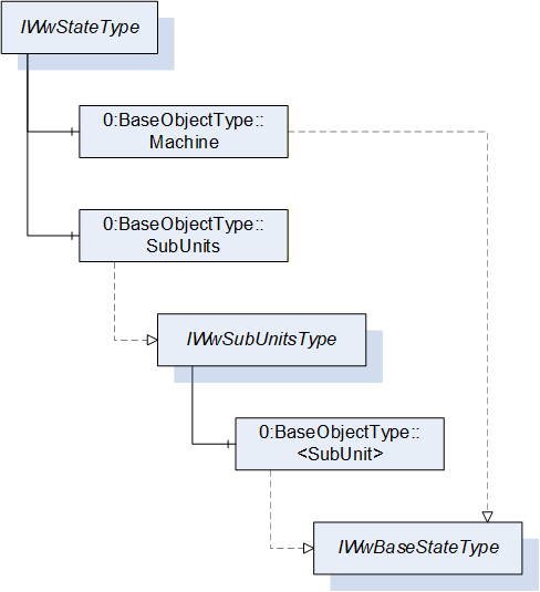
The IWwStateType provides the machine state and is formally defined in Table 18.
| Attribute | Value | ||||
| BrowseName | IWwStateType | ||||
| IsAbstract | True | ||||
| References | Node Class | BrowseName | DataType | TypeDefinition | Other |
|---|---|---|---|---|---|
| Subtype of the BaseInterfaceType defined in OPC 10000-5 | |||||
| 0:HasComponent | Object | Machine | 0:BaseObjectType | M | |
| 0:HasComponent | Object | SubUnits | 0:BaseObjectType | O | |
| Conformance Units | |||||
|---|---|---|---|---|---|
| Woodworking SubUnits Monitoring | |||||
| Woodworking Unit State |
Each instance of an IWwStateType represents an instance of a machine state. In the simplest case, there is only the Machine Object. The SubUnits Object is used when a machine has multiple states. For example, a CNC machine can have several places where independent jobs are produced.
The Machine state does not summarize the SubUnits states. It does not have to be based on the SubUnits states. It is a decision of the machine manufacturer.
The KPI calculation has to be done individually based on the special machine instance and its states.
The units of the IWwStateType have additional subunits which are defined in Table 19.
| Source Path | Reference | NodeClass | BrowseName | DataType | TypeDefinition | Others |
| Machine | 0:HasInterface | ObjectType | IWwBaseStateType | |||
| SubUnits | 0:HasInterface | ObjectType | IWwSubUnitsType |
7.4 IWwSubUnitsType InterfaceType Definition
The IWwSubUnitsType provides a list of SubUnits and is formally defined in Table 20.
| Attribute | Value | |||||
| BrowseName | IWwSubUnitsType | |||||
| IsAbstract | True | |||||
| References | Node Class | BrowseName | DataType | TypeDefinition | Other | |
|---|---|---|---|---|---|---|
| Subtype of the BaseInterfaceType defined in OPC 10000-5 | ||||||
| 0:HasComponent | Object | <SubUnit> | 0:BaseObjectType | MP | ||
| Conformance Units | ||||||
|---|---|---|---|---|---|---|
| Woodworking SubUnits Monitoring |
Each <SubUnit> object with Interface IWwBaseStateType shall be put into this object. It represents an instance of a state. For example, a CNC machine can have two places where independent jobs are produced. Then there are two <SubUnit> Objects. They may be named "Place_1" and "Place_2".
The components of the IWwSubUnitsType have additional subunits which are defined in Table 21.
| Source Path | Reference | Node Class | BrowseName | DataType | TypeDefinition | Others |
| <SubUnit> | 0:HasInterface | ObjectType | IWwBaseStateType |
7.5 IWwBaseStateType InterfaceType Definition
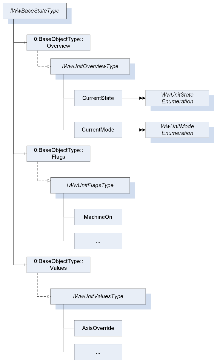
The IWwBaseStateType represents the state of a unit and is formally defined in Table 22. A unit can be a machine or part of a machine.
| Attribute | Value | ||||
| BrowseName | IWwBaseStateType | ||||
| IsAbstract | True | ||||
| References | Node Class | BrowseName | DataType | TypeDefinition | Other |
|---|---|---|---|---|---|
| Subtype of the BaseInterfaceType defined in OPC 10000-5 | |||||
| 0:HasComponent | Object | Overview | 0:BaseObjectType | M | |
| 0:HasComponent | Object | Flags | 0:BaseObjectType | O | |
| 0:HasComponent | Object | Values | 0:BaseObjectType | O | |
| Conformance Units | |||||
|---|---|---|---|---|---|
| Woodworking Machine Monitoring | |||||
| Woodworking SubUnits Monitoring | |||||
| Woodworking Unit State |
The Overview Object provides a general overview of the unit.
The Flags Object provides the flags of the unit.
The Values Object provides the counters and values of the unit.
The components of the IWwBaseStateType have additional subcomponents which are defined in Table 23.
| Source Path | Reference | NodeClass | BrowseName | DataType | TypeDefinition | Others |
| Overview | 0:HasInterface | ObjectType | IWwUnitOverviewType | |||
| Flags | 0:HasInterface | ObjectType | IWwUnitFlagsType | |||
| Values | 0:HasInterface | ObjectType | IWwUnitValuesType |
7.6 IWwUnitOverviewType InterfaceType Definition
The IWwUnitOverviewType represents the generalized overview of a unit and is formally defined in Table 24.
| Attribute | Value | ||||
| BrowseName | IWwUnitOverviewType | ||||
| IsAbstract | True | ||||
| References | Node Class | BrowseName | DataType | TypeDefinition | Other |
|---|---|---|---|---|---|
| Subtype of the BaseInterfaceType defined in OPC 10000-5 | |||||
| 0:HasComponent | Variable | CurrentState | WwUnitStateEnumeration | 0:BaseDataVariableType | M, RO |
| 0:HasComponent | Variable | CurrentMode | WwUnitModeEnumeration | 0:BaseDataVariableType | M, RO |
| Conformance Units | |||||
|---|---|---|---|---|---|
| Woodworking Unit State |
The CurrentState Variable provides the generalized state of the unit.
The CurrentMode Variable provides the generalized mode of the unit.
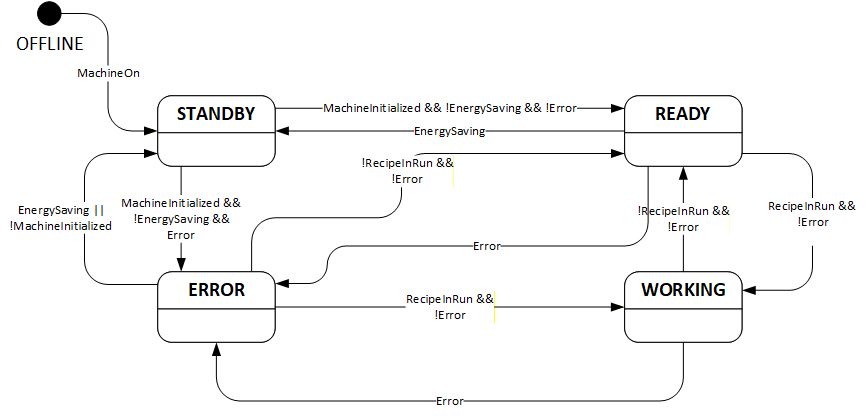
7.7 WwUnitStateEnumeration
This enumeration WwUnitStateEnumeration represents the generalized state of a unit. The enumeration is defined in Table 25.
| Name | Value | Description |
| OFFLINE | 0 | The unit is offline. |
| STANDBY | 1 | The unit is in standby. |
| READY | 2 | The unit is ready to start working. |
| WORKING | 3 | The unit is working. |
| ERROR | 4 | The unit is not able to work. The cause can be an alarm or error or user intervention. |
A unit state depends on the unit flags (see 7.9). Even if the unit flags are not provided in the AddressSpace they exist internally in the machine. If the device does not support EnergySaving, it is assumed that the variable value is False. Therefore, they are always the basis for the state:
OFFLINE:
| !MachineOn |
STANDBY:
| MachineOn && (!MachineInitialized || EnergySaving || (!Error && !Calibrated)) |
READY:
| MachineOn && MachineInitialized && !EnergySaving && !Error && Calibrated && !RecipeInRun |
WORKING:
| MachineOn && MachineInitialized && !EnergySaving && !Error && Calibrated && RecipeInRun |
ERROR:
| MachineOn && MachineInitialized && !EnergySaving && Error |
This is the state diagram of the UnitState:
Note: Since the unit state is an enumeration do not rely on the transitions. Only the logic of the unit flags counts.
Its representation in the AddressSpace is defined in Table 26.
| Attribute | Value | ||||
| BrowseName | WwUnitStateEnumeration | ||||
| IsAbstract | False | ||||
| References | Node Class | BrowseName | DataType | TypeDefinition | Other |
|---|---|---|---|---|---|
| Subtype of the Enumeration type defined in OPC 10000-5 | |||||
| 0:HasProperty | Variable | 0:EnumValues | 0:EnumValueType[] | 0:PropertyType | |
| Conformance Units | |||||
|---|---|---|---|---|---|
| Woodworking Unit State |
7.8 WwUnitModeEnumeration
This enumeration WwUnitModeEnumeration represents the generalized mode of a unit. The enumeration is defined in Table 27.
| Name | Value | Description |
| OTHER | 0 | This state is used if none of the other states below applies. |
| AUTOMATIC | 1 | The unit is in automatic mode. |
| SEMIAUTOMATIC | 2 | The unit is in semi-automatic mode. |
| MANUAL | 3 | The unit is in manual mode. |
| SETUP | 4 | The unit is in setup mode. |
| SLEEP | 5 | The unit is in sleep mode. Unit is still switched on, energy consumption reduced by e.g. reducing heating, switching drives off. Production is not possible. |
Its representation in the AddressSpace is defined in Table 28.
| Attribute | Value | ||||
| BrowseName | WwUnitModeEnumeration | ||||
| IsAbstract | False | ||||
| References | Node Class | BrowseName | DataType | TypeDefinition | Other |
|---|---|---|---|---|---|
| Subtype of the Enumeration type defined in OPC 10000-5 | |||||
| 0:HasProperty | Variable | 0:EnumValues | 0:EnumValueType[] | 0:PropertyType | |
| Conformance Units | |||||
|---|---|---|---|---|---|
| Woodworking Unit State |
7.9 IWwUnitFlagsType InterfaceType Definition
The IWwUnitFlagsType provides the flags of a unit and is formally defined in Table 29.
| Attribute | Value | ||||
| BrowseName | IWwUnitFlagsType | ||||
| IsAbstract | True | ||||
| References | Node Class | BrowseName | DataType | TypeDefinition | Other |
|---|---|---|---|---|---|
| Subtype of the BaseInterfaceType defined in OPC 10000-5 | |||||
| 0:HasComponent | Variable | MachineOn | 0:Boolean | 0:BaseDataVariableType | M, RO |
| 0:HasComponent | Variable | MachineInitialized | 0:Boolean | 0:BaseDataVariableType | M, RO |
| 0:HasComponent | Variable | PowerPresent | 0:Boolean | 0:BaseDataVariableType | M, RO |
| 0:HasComponent | Variable | AirPresent | 0:Boolean | 0:BaseDataVariableType | O, RO |
| 0:HasComponent | Variable | DustChipSuction | 0:Boolean | 0:BaseDataVariableType | O, RO |
| 0:HasComponent | Variable | Emergency | 0:Boolean | 0:BaseDataVariableType | M, RO |
| 0:HasComponent | Variable | Safety | 0:Boolean | 0:BaseDataVariableType | O, RO |
| 0:HasComponent | Variable | Calibrated | 0:Boolean | 0:BaseDataVariableType | M, RO |
| 0:HasComponent | Variable | Remote | 0:Boolean | 0:BaseDataVariableType | O, RO |
| 0:HasComponent | Variable | WorkpiecePresent | 0:Boolean | 0:BaseDataVariableType | O, RO |
| 0:HasComponent | Variable | Moving | 0:Boolean | 0:BaseDataVariableType | O, RO |
| 0:HasComponent | Variable | Error | 0:Boolean | 0:BaseDataVariableType | M, RO |
| 0:HasComponent | Variable | Alarm | 0:Boolean | 0:BaseDataVariableType | M, RO |
| 0:HasComponent | Variable | Warning | 0:Boolean | 0:BaseDataVariableType | M, RO |
| 0:HasComponent | Variable | Hold | 0:Boolean | 0:BaseDataVariableType | O, RO |
| 0:HasComponent | Variable | RecipeInRun | 0:Boolean | 0:BaseDataVariableType | M, RO |
| 0:HasComponent | Variable | RecipeInSetup | 0:Boolean | 0:BaseDataVariableType | O, RO |
| 0:HasComponent | Variable | RecipeInHold | 0:Boolean | 0:BaseDataVariableType | O, RO |
| 0:HasComponent | Variable | ManualActivityRequired | 0:Boolean | 0:BaseDataVariableType | O, RO |
| 0:HasComponent | Variable | LoadingEnabled | 0:Boolean | 0:BaseDataVariableType | O, RO |
| 0:HasComponent | Variable | WaitUnload | 0:Boolean | 0:BaseDataVariableType | O, RO |
| 0:HasComponent | Variable | WaitLoad | 0:Boolean | 0:BaseDataVariableType | O, RO |
| 0:HasComponent | Variable | EnergySaving | 0:Boolean | 0:BaseDataVariableType | O, RO |
| 0:HasComponent | Variable | ExternalEmergency | 0:Boolean | 0:BaseDataVariableType | O, RO |
| 0:HasComponent | Variable | MaintenanceRequired | 0:Boolean | 0:BaseDataVariableType | O, RO |
| 0:HasComponent | Variable | FeedRuns | 0:Boolean | 0:BaseDataVariableType | O, RO |
| Conformance Units | |||||
|---|---|---|---|---|---|
| Woodworking Machine Monitoring | |||||
| Woodworking SubUnits Monitoring | |||||
| Woodworking Unit State |
The MachineOn Variable is True if the machine is switched on. If the OPC UA Server runs on the machine this value is always True.
The MachineInitialized Variable is True if the MachineOn is True, the PLC and the control processes are running. The machine is ready for usage for the operator.
The PowerPresent Variable is True if the power supply is present (the drives are ready to move).
The AirPresent Variable is True if the air pressure is present in the machine.
The DustChipSuction Variable is True if the dust and chip suction is ready.
The Emergency Variable is True if at least one emergency button is pressed.
The Safety Variable is True if at least one safety device (light curtain, safety mat, …) has intervened.
The Calibrated Variable is True if all components of the machine that need to be calibrated are calibrated.
The Remote Variable is True if the machine is working with programs sent by the supervisor or other external application.
The WorkpiecePresent Variable is True if at least one piece is inside the machine.
The Moving Variable is True if at least one axis is moving.
The Error Variable is True if at least one reason exists which prevents the machine from working.
The Alarm Variable is True if at least one alarm exists.
The Warning Variable is True if at least one warning exists.
The Hold Variable is True if the movements are paused by the operator.
The RecipeInRun Variable is True if the machine runs its program. However, if the machine is paused by the program, the machine is considered to still be running its program, i.e. while the RecipeInHold Variable is True, the RecipeInRun cannot be False.
The RecipeInSetup Variable is True if the RecipeInRun is True and the machine is in the setup phase (example: automatic tool change).
The RecipeInHold Variable is True if the machine is paused by the program. This is only possible if the RecipeInRun Variable is also True.
The ManualActivityRequired Variable is True if a manual activity by the operator is required. The RecipeInRun is not affected.
The LoadingEnabled Variable is True if the unit is ready to get the next new part. If this is False no part can get into the unit.
The WaitUnload Variable is True if the machine is waiting to unload pieces.
The WaitLoad Variable is True if the machine is waiting for pieces.
The EnergySaving Variable is True if energy saving is activated on the machine.
The ExternalEmergency Variable is True if there is an emergency from the line controllercontroller.
The MaintenanceRequired Variable is True if maintenance is required.
The FeedRuns Variable is True if the feed is running on a throughfeed machine.
7.10 IWwUnitValuesType InterfaceType Definition
The IwwUnitValuesType represents the values of a unit and is formally defined in Table 30.
| Attribute | Value | ||||
| BrowseName | IWwUnitValuesType | ||||
| IsAbstract | True | ||||
| References | Node Class | BrowseName | DataType | TypeDefinition | Other |
|---|---|---|---|---|---|
| Subtype of the BaseInterfaceType defined in OPC 10000-5 | |||||
| 0:HasComponent | Variable | AxisOverride | 0:UInt32 | 0:BaseAnalogType | O, RO |
| 0:HasComponent | Variable | SpindleOverride | 0:UInt32 | 0:BaseAnalogType | O, RO |
| 0:HasComponent | Variable | FeedSpeed | 0:Double | 0:BaseAnalogType | O, RO |
| 0:HasComponent | Variable | ActualCycle | 0:Double | 0:BaseAnalogType | O, RO |
| 0:HasComponent | Variable | AbsoluteMachineOffTime | 0:UInt64 | 0:BaseAnalogType | O, RO |
| 0:HasComponent | Variable | AbsoluteStandbyTime | 0:UInt64 | 0:BaseAnalogType | O, RO |
| 0:HasComponent | Variable | RelativeStandbyTime | 0:UInt64 | 0:BaseAnalogType | O, RO |
| 0:HasComponent | Variable | AbsoluteReadyTime | 0:UInt64 | 0:BaseAnalogType | O, RO |
| 0:HasComponent | Variable | RelativeReadyTime | 0:UInt64 | 0:BaseAnalogType | O, RO |
| 0:HasComponent | Variable | AbsoluteWorkingTime | 0:UInt64 | 0:BaseAnalogType | O, RO |
| 0:HasComponent | Variable | RelativeWorkingTime | 0:UInt64 | 0:BaseAnalogType | O, RO |
| 0:HasComponent | Variable | AbsoluteErrorTime | 0:UInt64 | 0:BaseAnalogType | O, RO |
| 0:HasComponent | Variable | RelativeErrorTime | 0:UInt64 | 0:BaseAnalogType | O, RO |
| 0:HasComponent | Variable | AbsoluteMachineOnTime | 0:UInt64 | 0:BaseAnalogType | O, RO |
| 0:HasComponent | Variable | RelativeMachineOnTime | 0:UInt64 | 0:BaseAnalogType | O, RO |
| 0:HasComponent | Variable | AbsolutePowerPresentTime | 0:UInt64 | 0:BaseAnalogType | O, RO |
| 0:HasComponent | Variable | RelativePowerPresentTime | 0:UInt64 | 0:BaseAnalogType | O, RO |
| 0:HasComponent | Variable | AbsoluteProductionTime | 0:UInt64 | 0:BaseAnalogType | O, RO |
| 0:HasComponent | Variable | RelativeProductionTime | 0:UInt64 | 0:BaseAnalogType | O, RO |
| 0:HasComponent | Variable | AbsoluteProductionWithoutWorkpieceTime | 0:UInt64 | 0:BaseAnalogType | O, RO |
| 0:HasComponent | Variable | RelativeProductionWithoutWorkpieceTime | 0:UInt64 | 0:BaseAnalogType | O, RO |
| 0:HasComponent | Variable | AbsoluteProductionWaitWorkpieceTime | 0:UInt64 | 0:BaseAnalogType | O, RO |
| 0:HasComponent | Variable | RelativeProductionWaitWorkpieceTime | 0:UInt64 | 0:BaseAnalogType | O, RO |
| 0:HasComponent | Variable | AbsoluteRunsGood | 0:UInt64 | 0:BaseAnalogType | O, RO |
| 0:HasComponent | Variable | RelativeRunsGood | 0:UInt64 | 0:BaseAnalogType | O, RO |
| 0:HasComponent | Variable | AbsoluteRunsTotal | 0:UInt64 | 0:BaseAnalogType | O, RO |
| 0:HasComponent | Variable | RelativeRunsTotal | 0:UInt64 | 0:BaseAnalogType | O, RO |
| 0:HasComponent | Variable | AbsoluteRunsAborted | 0:UInt64 | 0:BaseAnalogType | O, RO |
| 0:HasComponent | Variable | RelativeRunsAborted | 0:UInt64 | 0:BaseAnalogType | O, RO |
| 0:HasComponent | Variable | AbsoluteLength | 0:UInt64 | 0:BaseAnalogType | O, RO |
| 0:HasComponent | Variable | RelativeLength | 0:UInt64 | 0:BaseAnalogType | O, RO |
| 0:HasComponent | Variable | AbsolutePiecesIn | 0:UInt64 | 0:BaseAnalogType | O, RO |
| 0:HasComponent | Variable | RelativePiecesIn | 0:UInt64 | 0:BaseAnalogType | O, RO |
| 0:HasComponent | Variable | AbsolutePiecesOut | 0:UInt64 | 0:BaseAnalogType | O, RO |
| 0:HasComponent | Variable | RelativePiecesOut | 0:UInt64 | 0:BaseAnalogType | O, RO |
| Conformance Units | |||||
|---|---|---|---|---|---|
| Woodworking Machine Monitoring | |||||
| Woodworking SubUnits Monitoring | |||||
| Woodworking Unit State |
Note: For OEE or KPI calculations the absolute and relative values might not be good enough. The term "Absolute" depends on the manufacturer. It may be reset on the machine or the InitialOperationDate is used for the start. The reset function can usually only be done by the service or the manufacturer. Therefore, it cannot be done by the OPC UA Client. Maybe one manufacturer has this feature.
The AxisOverride Variable provides the override for the axis in percent.
The SpindleOverride Variable provides the override for the spindle in percent.
The FeedSpeed Variable provides the feed speed in m/min for throughfeed machines. The values can be negative.
The ActualCycle Variable provides the parts per minutes.
The AbsoluteMachineOffTime can be calculated by the machine. The shutdown time and the starting time have to be stored on the machine.
The AbsoluteStandbyTime Variable provides the absolute time of the STANDBY state in msec.
The RelativeStandbyTime Variable provides the relative time since startup of the STANDBY state in msec.
The AbsoluteReadyTime Variable provides the absolute time of the READY state in msec.
The RelativeReadyTime Variable provides the relative time since startup of the READY state in msec.
The AbsoluteWorkingTime Variable provides the absolute time of the WORKING state in msec.
The RelativeWorkingTime Variable provides the relative time since startup of the WORKING state in msec.
The AbsoluteErrorTime Variable provides the absolute time of the ERROR state in msec.
The RelativeErrorTime Variable provides the relative time since startup of the ERROR state in msec.
The AbsoluteMachineOnTime Variable provides the absolute time in msec the machine is turned on based on the MachineOn state.
The RelativeMachineOnTime Variable provides the relative time in msec since startup the machine is turned on based on the MachineOn state.
The AbsolutePowerPresentTime Variable provides the absolute time in msec the machine has power on based on the PowerPresent state.
The RelativePowerPresentTime Variable provides the relative time in msec since startup the machine has power on based on the PowerPresent state.
The AbsoluteProductionTime Variable provides the absolute time in msec of the machine is working at least with one workpiece based on the RecipeInRun and WorkpiecePresent state.
The RelativeProductionTime Variable provides the relative time in msec since startup of the machine is working at least with one workpiece based on the RecipeInRun and WorkpiecePresent state.
The AbsoluteProductionWithoutWorkpieceTime Variable provides the absolute time in msec of the machine is working but without workpieces inside based on the RecipeInRun state and the negated WorkpiecePresent state.
The RelativeProductionWithoutWorkpieceTime Variable provides the relative time in msec since startup of the machine is working but without workpieces inside based on the RecipeInRun state and the negated WorkpiecePresent state.
The AbsoluteProductionWaitWorkpieceTime Variable provides the absolute time in msec of the machine is in working mode, bring the consent out to insert workpiece but no workpiece incoming from the previous machine based on the ReceipeInRun and WaitLoad state.
The RelativeProductionWaitWorkpieceTime Variable provides the relative time in msec waiting for workpieces since startup of the machine is in working mode, bring the consent out to insert workpiece but no workpiece incoming from the previous machine based on the ReceipeInRun and WaitLoad state.
The AbsoluteRunsGood Variable provides the absolute count of finished runs.
The RelativeRunsGood Variable provides the relative count of finished runs since the machine was last switched on.
The AbsoluteRunsTotal Variable provides the absolute count of total runs.
The RelativeRunsTotal Variable provides the relative count of total runs since the machine was last switched on.
The AbsoluteRunsAborted Variable provides the absolute count of aborted runs.
The RelativeRunsAborted Variable provides the relative count of aborted runs since the machine was last switched on.
The AbsoluteLength Variable provides the absolute produced length in mm.
The RelativeLength Variable provides the relative produced length in mm since the machine was last switched on.
The AbsolutePiecesIn Variable provides the absolute count of pieces which came into the machine.
The RelativePiecesIn Variable provides the relative count of pieces which came into the machine since the machine was last switched on.
The AbsolutePiecesOut Variable provides the absolute count of pieces which came out of the machine.
The RelativePiecesOut Variable provides the relative count of pieces which came out of the machine since the machine was last switched on.
7.11 IWwEventMessageType InterfaceType Definition
The IWwEventMessageType provides the common extensions for all events and conditions and is formally defined in Table 31. Each instance definition that includes this interface with a 0:HasInterface reference defines the predefined extensions.
| Attribute | Value | ||||
| BrowseName | IWwEventMessageType | ||||
| IsAbstract | True | ||||
| References | Node Class | BrowseName | DataType | TypeDefinition | Other |
|---|---|---|---|---|---|
| Subtype of the 0:BaseInterfaceType defined in OPC 10000-5 | |||||
| 0:HasProperty | Variable | EventCategory | WwEventCategoryEnumeration | 0:PropertyType | M, RO |
| 0:HasProperty | Variable | MessageId | 0:String | 0:PropertyType | M, RO |
| 0:HasProperty | Variable | MessageName | 0:String | 0:PropertyType | O, RO |
| 0:HasProperty | Variable | PathParts | 0:String[] | 0:PropertyType | M, RO |
| 0:HasProperty | Variable | Group | 0:String | 0:PropertyType | O, RO |
| 0:HasProperty | Variable | LocalizedMessages | 0:LocalizedText[] | 0:PropertyType | O, RO |
| 0:HasProperty | Variable | Arguments | WwMessageArgumentDataType[] | 0:PropertyType | O, RO |
| Conformance Units | |||||
|---|---|---|---|---|---|
| Woodworking Event Messages |
The EventCategory Variable provides the category of the event.
The MessageId Variable is a unique Identifier like a number or name of the message in the cause path (PathParts) determined Module. Example: "A4711" or "1".
The MessageName Variable is a short name like a number or title to reference a translation of the general message text. Example: "ID_MSG_EmergencyAlarm".
The PathParts Variable is an array of Path information strings based on a Server independent hierarchical structure of modules or an application specific expansion of that. It is an additional location information beside the SourceName. Example:
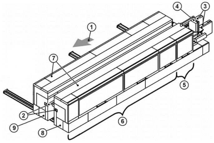
| Key | |
| 1 = Machine with feed direction 2 = Top pressure beam 3 = Chain beam 4 = Control 5 = Sizing with Milling 1 and Milling 2 inside 6 = Addition operation zone 7 = Integrated enclosure 8 = Fixed side 9 = Movable side |
| "Machine" | "FixedSide" | "Sizing" | "Milling1" |
The Group Variable specifies the class or group of the Message. The contents are set by the machine manufacturer. Examples are "safety", "emergency", "consumable".
The LocalizedMessages Variable contains an array of localized messages corresponding to the installed Server languages. The 0:Message property contains the content of the LocalizedMessages entry, which corresponds to the currently set language of the session. There are no placeholders in the messages. The 0:Message property and the LocalizedMessages are all resolved.
The Arguments Variable is an argument that can be used to parameterize the message. The number of the indexing in the array corresponds to the placeholder number in the message text. This ensures that the formatting functions of the implementations enable the localized message texts to be created. If a Client wants to use this feature, it has to use the MessageId. With this Id the raw message can be taken from a repository of the woodworking manufacturer. Then the placeholders can be resolved using the Arguments. The format of the raw message is up to the manufacturer.
7.12 WwEventCategoryEnumeration
This enumeration WwEventCategoryEnumeration represents the category of an event. The enumeration is defined in Table 32.
| Name | Value | Description |
| OTHER | 0 | No other event category applies or it is unknown. |
| DIAGNOSTIC | 1 | This category is used for messages for debugging and diagnostic purposes. They can be ignored by Clients (Diagnostic messages to operator, e.g. "system is ready") |
| INFORMATION | 2 | Messages of this category do not require a Client to read them for normal operation. The woodworking system can safely continue normal operation even if this message is ignored. (Help messages to operator, e.g. "select Auto mode and press Start") |
| WARNING | 3 | This category describes messages that in general could have moderate importance. Missing or ignoring such a message has no serious consequences. The woodworking system could request acknowledgement or acknowledgement and confirmation if needed. (Warning message to operator, e.g. "tool life will soon be reached") |
| ALARM | 4 | The goal of an alarm is to inform operators about conditions in a timely manner and allow the operator to take some action before some consequences occur. The consequences may be economic (product is not usable and must be discarded), may be physical (overheating), may be related to safety (fire or destruction could occur) or any of a number of other possibilities. Typically, if no action is taken related to an alarm for some period of time the process will cross some threshold at which point consequences will start to occur, likely causing an Error condition. According to this definition an alarm message usually requires an acknowledgement and it may be decided that also a confirmation is needed. |
| ERROR | 5 | This category is used for error messages associated with problems that need human interaction. An Error occurs if the situation has critical consequences for the machine process. For example, the protection of human life, of the environment, or of the machine itself, through safety mechanisms that block the process to prevent any harmful situation. This kind of situation cannot be solved automatically and confirmation by an operator is mandatory. |
This specification does not intend to determine in which manner acknowledgement and confirmation are given by operators: this could be done directly on a machine (e.g. through a SCADA or HMI) or/and by an OPC UA Client through OPC UA Alarms and Conditions mechanisms, if available.
Its representation in the AddressSpace is defined in Table 33.
| Attribute | Value | ||||
| BrowseName | WwEventCategoryEnumeration | ||||
| IsAbstract | False | ||||
| References | Node Class | BrowseName | DataType | TypeDefinition | Other |
|---|---|---|---|---|---|
| Subtype of the Enumeration type defined in OPC 10000-5 | |||||
| 0:HasProperty | Variable | 0:EnumValues | 0:EnumValueType[] | 0:PropertyType | |
| Conformance Units | |||||
|---|---|---|---|---|---|
| Woodworking Event Messages |
7.13 WwMessageArgumentDataType
This structure definition extends the argument structure with an argument value. The structure is defined in Table 34.
| Name | Type | Description |
| WwMessageArgumentDataType | structure | Subtype of the 0:Argument defined in OPC UA Part 3 |
Value | WwMessageArgumentValueDataType | The variable contains the value of the argument. |
Its representation in the AddressSpace is defined in Table 35.
| Attribute | Value | ||||
| BrowseName | WwMessageArgumentDataType | ||||
| IsAbstract | False | ||||
| References | Node Class | BrowseName | DataType | TypeDefinition | Other |
|---|---|---|---|---|---|
| Subtype of the 0:Argument defined in OPC UA Part 3 | |||||
| Conformance Units | |||||
|---|---|---|---|---|---|
| Woodworking Event Messages |
7.14 WwMessageArgumentValueDataType
This union defines the possible types of an argument value. The structure is defined in Table 36.
| Name | Type | Description |
| WwMessageArgumentValueDataType | structure | Subtype of the 0:Union defined in OPC UA Part 3 |
Array | WwMessageArgumentValueDataType[] | The content of the value as an array of the own type |
Boolean | Boolean | The content of the value as a boolean |
Int16 | Int16 | The content of the value as a 16 bit integer |
Int32 | Int32 | The content of the value as a 32 bit integer |
Int64 | Int64 | The content of the value as a 64 bit integer |
SByte | SByte | The content of the value as a 8 bit integer |
UInt16 | UInt16 | The content of the value as a 16 bit unsigned integer |
UInt32 | UInt32 | The content of the value as a 32 bit unsigned integer |
UInt64 | UInt64 | The content of the value as a 64 bit unsigned integer |
Byte | Byte | The content of the value as a 8 bit unsigned integer |
DateTime | DateTime | The content of the value as a datetime |
Guid | Guid | The content of the value as a GUID |
LocalizedText | LocalizedText | The content of the value as a localized text |
Double | Double | The content of the value as a double |
Float | Float | The content of the value as a float |
String | String | The content of the value as a string |
Other | String | The content of the value has no standard format and is instantiated as a string |
Its representation in the AddressSpace is defined in Table 37.
| Attribute | Value | ||||
| BrowseName | WwMessageArgumentValueDataType | ||||
| IsAbstract | False | ||||
| References | Node Class | BrowseName | DataType | TypeDefinition | Other |
|---|---|---|---|---|---|
| Subtype of the 0:Union defined in OPC UA Part 3 | |||||
| Conformance Units | |||||
|---|---|---|---|---|---|
| Woodworking Event Messages |
7.15 WwBaseEventType ObjectType Definition
The WwBaseEventType represents a message event from a module and is formally defined in Table 38.
| Attribute | Value | ||||
| BrowseName | WwBaseEventType | ||||
| IsAbstract | False | ||||
| References | Node Class | BrowseName | DataType | TypeDefinition | Other |
|---|---|---|---|---|---|
| Subtype of the 0:BaseEventType defined in OPC UA Part 5 | |||||
| 0:HasInterface | ObjectType | IWwEventMessageType | |||
| Applied from IWwEventMessageType | |||||
| 0:HasProperty | Variable | EventCategory | WwEventCategoryEnumeration | 0:PropertyType | M, RO |
| 0:HasProperty | Variable | MessageId | 0:String | 0:PropertyType | M, RO |
| 0:HasProperty | Variable | MessageName | 0:String | 0:PropertyType | O, RO |
| 0:HasProperty | Variable | PathParts | 0:String[] | 0:PropertyType | M, RO |
| 0:HasProperty | Variable | Group | 0:String | 0:PropertyType | O, RO |
| 0:HasProperty | Variable | LocalizedMessages | 0:LocalizedText[] | 0:PropertyType | O, RO |
| 0:HasProperty | Variable | Arguments | WwMessageArgumentDataType[] | 0:PropertyType | O, RO |
| Conformance Units | |||||
|---|---|---|---|---|---|
| Woodworking Event Messages |
IWwEventMessageType and its members are described in 7.11.
7.16 WwConditionType ObjectType Definition
The WwConditionType represents a stateful message event from a module and is formally defined in Table 39. It is used to classify conditions to recognize event messages with the extensions of the interface IWwEventMessageType. The 0:EnabledState of the linked condition is used to map the state of an event message. The behavior corresponds to the description of the 0:ConditionType defined in OPC UA Part 9.
| Attribute | Value | ||||
| BrowseName | WwConditionType | ||||
| IsAbstract | False | ||||
| References | Node Class | BrowseName | DataType | TypeDefinition | Other |
|---|---|---|---|---|---|
| Subtype of the 0:ConditionType defined in OPC UA Part 9 | |||||
| 0:HasInterface | ObjectType | IWwEventMessageType | |||
| Applied from IWwEventMessageType | |||||
| 0:HasProperty | Variable | EventCategory | WwEventCategoryEnumeration | 0:PropertyType | M, RO |
| 0:HasProperty | Variable | MessageId | 0:String | 0:PropertyType | M, RO |
| 0:HasProperty | Variable | MessageName | 0:String | 0:PropertyType | O, RO |
| 0:HasProperty | Variable | PathParts | 0:String[] | 0:PropertyType | M, RO |
| 0:HasProperty | Variable | Group | 0:String | 0:PropertyType | O, RO |
| 0:HasProperty | Variable | LocalizedMessages | 0:LocalizedText[] | 0:PropertyType | O, RO |
| 0:HasProperty | Variable | Arguments | WwMessageArgumentDataType[] | 0:PropertyType | O, RO |
| Conformance Units | |||||
|---|---|---|---|---|---|
| Woodworking Event Messages |
IWwEventMessageType and its members are described in 7.11.
7.17 WwAcknowledgeableConditionType ObjectType Definition
The WwAcknowledgeableConditionType represents a stateful message event from a module and is formally defined in Table 40. It is used to classify conditions to recognize acknowledgeable and confirmable event messages with the extensions of the interface IWwEventMessageType. The 0:EnabledState of the linked condition is used to map the active state of an event message. The behavior corresponds to the description of the 0:AcknowledgeableConditionType defined in OPC UA Part 9.
| Attribute | Value | ||||
| BrowseName | WwAcknowledgeableConditionType | ||||
| IsAbstract | False | ||||
| References | Node Class | BrowseName | DataType | TypeDefinition | Other |
|---|---|---|---|---|---|
| Subtype of the 0:AcknowledgeableConditionType defined in OPC UA Part 9 | |||||
| 0:HasInterface | ObjectType | IWwEventMessageType | |||
| Applied from IWwEventMessageType | |||||
| 0:HasProperty | Variable | EventCategory | WwEventCategoryEnumeration | 0:PropertyType | M, RO |
| 0:HasProperty | Variable | MessageId | 0:String | 0:PropertyType | M, RO |
| 0:HasProperty | Variable | MessageName | 0:String | 0:PropertyType | O, RO |
| 0:HasProperty | Variable | PathParts | 0:String[] | 0:PropertyType | M, RO |
| 0:HasProperty | Variable | Group | 0:String | 0:PropertyType | O, RO |
| 0:HasProperty | Variable | LocalizedMessages | 0:LocalizedText[] | 0:PropertyType | O, RO |
| 0:HasProperty | Variable | Arguments | WwMessageArgumentDataType[] | 0:PropertyType | O, RO |
| Conformance Units | |||||
|---|---|---|---|---|---|
| Woodworking Event Messages |
IWwEventMessageType and its members are described in 7.11.
7.18 WwAlarmConditionType ObjectType Definition
The WwAlarmConditionType represents a stateful message event from a module and is formally defined in Table 41. It is used to classify conditions to recognize acknowledgeable and confirmable event messages with the extensions of the interface IWwEventMessageType. As an enhancement to the more general conditions, an alarm contains an additional 0:ActiveState variable, which can be used to map the active state of an event message. In combination with this, the 0:EnabledState is used to control the usability of the condition. The behavior corresponds to the description of the 0:AlarmConditionType defined in OPC UA Part 9.
| Attribute | Value | ||||
| BrowseName | WwAlarmConditionType | ||||
| IsAbstract | False | ||||
| References | Node Class | BrowseName | DataType | TypeDefinition | Other |
|---|---|---|---|---|---|
| Subtype of the 0:AlarmConditionType defined in OPC UA Part 9 | |||||
| 0:HasInterface | ObjectType | IWwEventMessageType | |||
| Applied from IWwEventMessageType | |||||
| 0:HasProperty | Variable | EventCategory | WwEventCategoryEnumeration | 0:PropertyType | M, RO |
| 0:HasProperty | Variable | MessageId | 0:String | 0:PropertyType | M, RO |
| 0:HasProperty | Variable | MessageName | 0:String | 0:PropertyType | O, RO |
| 0:HasProperty | Variable | PathParts | 0:String[] | 0:PropertyType | M, RO |
| 0:HasProperty | Variable | Group | 0:String | 0:PropertyType | O, RO |
| 0:HasProperty | Variable | LocalizedMessages | 0:LocalizedText[] | 0:PropertyType | O, RO |
| 0:HasProperty | Variable | Arguments | WwMessageArgumentDataType[] | 0:PropertyType | O, RO |
| Conformance Units | |||||
|---|---|---|---|---|---|
| Woodworking Event Messages |
IWwEventMessageType and its members are described in 7.11.
7.19 WwEventsDispatcherType ObjectType
The WwEventsDispatcherType represents a container that is an event dispatcher for machine events and is formally defined in Table 42.
| Attribute | Value | ||||
| BrowseName | WwEventsDispatcherType | ||||
| IsAbstract | False | ||||
| References | Node Class | BrowseName | DataType | TypeDefinition | Other |
|---|---|---|---|---|---|
| Subtype of the 0:BaseObjectType defined in OPC 10000-5 | |||||
| 0:GeneratesEvent | ObjectType | 0:BaseEventType | |||
| 0:GeneratesEvent | ObjectType | WwBaseEventType | |||
| 0:GeneratesEvent | ObjectType | WwConditionType | |||
| 0:GeneratesEvent | ObjectType | WwAcknowledgeableConditionType | |||
| 0:GeneratesEvent | ObjectType | WwAlarmConditionType | |||
| Conformance Units | |||||
|---|---|---|---|---|---|
| Woodworking Machine Events | |||||
| Woodworking Event Propagation | |||||
| Woodworking Event Messages | |||||
| Woodworking Stateful Event Messages |
A wide variety of events and states can trigger messages on a plant, machine or component. Events and the associated messages are rather temporary and therefore cannot be subscribed directly. However, filtering can be realized with the event types like WwBaseEventType, WwConditionType, WwAcknowledgeableConditionType or WwAlarmConditionType. The woodworking events implement the interface IWwEventMessageType.
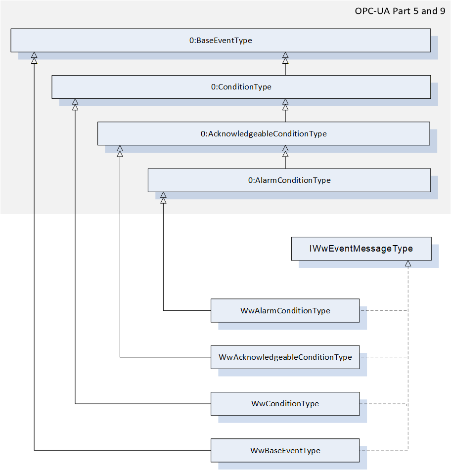
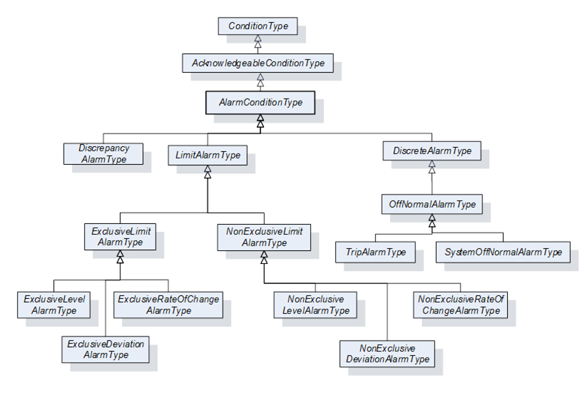
Woodworking machines do not need to provide the woodworking Types like WwBaseEventType. Instead, it can be an object based on any OPC UA 0:BaseEventType or a subtype, which also contains an implementation of the IWwEventMessageType interface. So it is possible to use the full range of OPC UA AlarmTypes like 0:LimitAlarmType:
Note: Due to the implementation of the selected SDK (Software Developer Kit) to support the realization of the server application, it is possible that the condition methods such as AddComment, Acknowledge or Confirm cannot be used for conditions outside the AddressSpace.
7.20 Job-Order-Input and Job-Order-Response Information
7.20.1 Overview
This specification extends the standardized parameters of Job-Order-Input and Job-Order-Response Information of the OPC UA for Machinery, Part 3: JobManagement specification. All extended parameters have the Woodworking prefix "Ww" for the Id.
7.20.2 JobOrderParameters and JobResponseData
Table 43 lists the predefined key-value pairs for 2:JobOrderParameters and 2:JobResponseData. The table indicates, in which data structure the key-value pair should preferably to be used. An "X" in "In" indicates it may be used in 2:JobOrderParameters. And an "X" in "Out" indicates it may be used in 2:JobResponseData.
As an extension to "OPC40001-3" (OPC UA for Machinery, Part 3: JobManagement), all in-parameters can also be used as out-parameters. An in-parameter is normally set via a Manufacturing Execution System (MES) and an out-parameter is usually determined on a machine. In certain applications, this is determined jointly by the manufacturer and the customer.
| ID | DataType of Value | Description | EngineeringUnits | Sub-parameters | In | Out |
| WwSerialProduction | 0:Boolean | If this flag is set, production will continue until it is interrupted manually or by another reason. | - | - | X | - |
| WwProductionDatasetId | 0:String | Unique identification of the production dataset. Depending on the type of machine it can be: Program Recipe Macro etc. | - | - | X | - |
| WwRawLength | 0:Double | Raw length of the workpiece. If the dimension of a workpiece changes during the production process, then this raw value can be provided. The parameter is not required if the length does not change. | Product- specific | - | X | - |
| WwLength | 0:Double | Length of the workpiece. If the dimension of a workpiece changes during the production process, this is the resulting length. | Product- specific | - | X | - |
| WwRawWidth | 0:Double | Raw width of the workpiece. If the dimension of a workpiece changes during the production process, then this raw value can be provided. The parameter is not required if the width does not change. | Product- specific | - | X | - |
| WwWidth | 0:Double | Width of the workpiece. If the dimension of a workpiece changes during the production process, this is the resulting width. | Product- specific | - | X | - |
| WwRawHeight | 0:Double | Raw height of the workpiece. If the dimension of a workpiece changes during the production process, then this raw value can be provided. The parameter is not required if the height does not change. | Product- specific | - | X | - |
| WwHeight | 0:Double | Height of the workpiece. If the dimension of a workpiece changes during the production process, this is the resulting height. | Product- specific | - | X | - |
| WwProductionSubDatasetIds | 0:String[] | Array of unique sub-production dataset identifiers. If the order of the sub-production datasets has to be payed attention to, then the sequence within the array is relevant. Dependent on the type of machine it can be: SubProgram SubRecipe SubMacro etc. | - | - | X | - |
| WwPlannedFeedspeed | 0:Double | Planned feed speed. Planned movement speed of the workpieces in the machine. If WwPlannedCycle is also provided, the machine determines its use. | Product- specific | - | X | - |
| WwActualFeedspeed | 0:Double | Actual feed speed. Actual movement speed of the workpieces in the machine. | Product- specific | - | - | X |
| WwPlannedLoadingFeedspeed | 0:Double | Planned feed speed at the loading point. | Product- specific | - | X | - |
| WwActualLoadingFeedspeed | 0:Double | Actual feed speed at the loading point. | Product- specific | - | - | X |
| WwPlannedUnloadingFeedspeed | 0:Double | Planned feed speed at the unloading point. | Product- specific | - | X | - |
| WwActualUnloadingFeedspeed | 0:Double | Actual feed speed at the unloading point. | Product- specific | - | - | X |
| WwPlannedCycle | 0:Double | Planned production cycle. If WwPlannedFeedspeed is also provided, the machine determines its use. | Product- specific | - | X | - |
| WwActualCycle | 0:Double | Actual production cycle. | Product- specific | - | - | X |
| WwPlannedLoadingCycle | 0:Double | Planned production cycle at the loading point. If WwPlannedLoadingFeedspeed is also provided, the machine determines its use. | Product- specific | - | X | - |
| WwActualLoadingCycle | 0:Double | Actual production cycle at the loading point. | Product- specific | - | - | X |
| WwPlannedUnloadingCycle | 0:Double | Planned production cycle at the unloading point. If WwPlannedUnloadingFeedspeed is also provided, the machine determines its use. | Product- specific | - | X | - |
| WwActualUnloadingCycle | 0:Double | Actual production cycle at the unloading point. | Product- specific | - | - | X |
| WwPlannedRepair | 0:Boolean | Planned repair processing of a workpiece. (True = yes, False = no) If the incoming workpiece is to be repaired, this can be sent as an input. | - | - | X | - |
| WwRepair | 0:Boolean | Repair processing of a workpiece. (True = yes, False = no) This flag can be set to True as an output parameter if the quality of the workpiece after processing by the machine is not acceptable. | - | - | - | X |
| WwEdgeIds | 0:String[] | Ids of the edge material to be applied. | - | - | X | - |
| WwDischarge | 0:Boolean | Eject workpiece. (True = yes, False = no / back transport) | - | - | X | - |
| WwDischargeType | 0:UInt32 | Type of discharge 0 - not relevant 1 - manually 2 - automatically | - | - | X | - |
| WwLoadingType | 0:UInt32 | Type of loading 0 - not relevant 1 - manually 2 - automatically | - | - | X | - |
| WwBarcode | 0:String | Barcode. The content depends on the customer. It can be provided as an input parameter by the MES or as an output parameter by scanning it by a barcode reader. | - | - | X | X |
| WwWorkpieceMaterialIds | 0:String[] | E.g. type of wood: Possible example content: - "Spruce" - "Beech" - "HardWood" - etc | - | - | X | - |
| WwSurfaceIds | 0:String[] | Ids of the surface material to be applied | - | - | X | - |
| WwProcessing | 0:Boolean | True: The production step will be processed. False: No processing (e.g. in a Throughfeed machine, only transport) | - | - | X | - |
| WwFlipAngle | 0:UInt32 | Degrees to flip. 180° means flipping on the other side. | Product- specific | - | X | - |
| WwTurnAngle | 0:UInt32 | Degrees to turn, e.g. 90° | Product- specific | - | X | - |
| WwXMirror | 0:Boolean | False: No mirror True: Mirrored in X | - | - | X | - |
| WwYMirror | 0:Boolean | False: No mirror True: Mirrored in Y | - | - | X | - |
| WwPlannedProductionPlaceId | 0:String | Planned location where production has to take place, e.g. the number of the table on a CNC machine. | - | - | X | - |
| WwActualProductionPlaceId | 0:String | Actual location where the production took place, e.g. the number of the table on a CNC machine. | - | - | - | X |
| WwProductionMode | 0:String | Production mode to use. On the machine side different production modes can be defined by the user, (e.g. on a CNC machine "Mirrored" and "Place2" is equal to WwProductionMode 1) The MES can send this WwProductionMode with a job. | - | - | X | - |
| WwPlannedAmountOfInputWork pieces | 0:UInt32 | E.g. amount of panels for sawing machines | Product- specific | - | X | - |