The standardization and depiction of the wire harness machinery rely on several fundamental building blocks, namely:
- Identification
- ItemState
- ApplicationMode
- Job Management
- Result Management
In this sector-specific adaptation, both Job Management and Result Management are extended to meet unique industry needs, while the other building blocks are incorporated unchanged.
Figure 1 illustrates the schematic structure of a job in the wire harness domain and its interplay with the results and the actual assets involved.
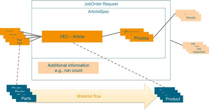
Figure 1 – Abstract overview of a Wire Harness Job
To execute, or run a job, multiple parts are supplied to the machine and processed into products. A product aligns with a specification, referred to as 'ArticleSpec.' An ArticleSpec contains process information, article information, and a reference to the parts used (“Part info“ in the above image). Additionally, measurement results may be captured by the machine or the machine operator during setup and production. During setup, a set of verification measurements may be gathered that apply to the entire production lot. During production, a set of monitoring measurements may be collected for each item produced. The set of validation and monitoring processes are part of the article specification. These are understood within this specification to be processed on an instance-dependent basis. Each job can also have additional status information, which is stored in the Job Response (see OPC UA 40001-1).
The Vehicle Electric Container (VEC) is a standardized data model that facilitates the exchange, collaboration, and archiving of electrical network, wiring harness and wiring harness component information in the automotive industry. It serves as a tool-independent digital representation of a vehicle's electrical system, supporting the conceptualization and design of logical mockups, the exchange of component data or the product specification of wiring harnesses. The VEC helps ensure traceability throughout the lifecycle of a vehicle's electrical system.
Developed under the guidance of the VDA and the prostep ivip Association, VEC is a standard in the automotive industry, and is published as VDA 4968 and PSI21.
Note: The complete VEC standard can be found here: https://ecad-wiki.prostep.org/specifications/vec/
This Companion Specification utilizes subsets of the VEC data model for the description of 'Article' and 'Part' information (see Figure 2). There are multiple reasons for this:
- It enhances interoperability and consistency in the exchange of data across different systems and equipment within the automotive industry. Article and Part information is used throughout the process, not only in communication with production machines.
- Components for the wiring harness (Parts) and the wiring harness itself (Article) are diverse, with great variety and many facets. Reusing vetted modelling concepts for their description increases the quality of these aspects for this Companion Specification and enables accelerated and efficient definitions.
- It allows this Companion Specification to focus on the additional aspects that are relevant to machine communication, such as job management, result data and process parameters.
Due to its scope as a common language in the wiring harness value chain, the VEC standard includes modelling concepts that are necessary in the design and engineering process, but not during production or for certain machine types (e.g., system schematics). The data model elements used in this Companion Specification are a subset of the complete data model defined by the VEC standard.
Concrete mapping between VEC and OPC UA is described in section 9.
Figure 2 – VEC as Part of the Job Description
The key concepts of the VEC are DocumentVersion and 7:PartVersion (see Figure 3).
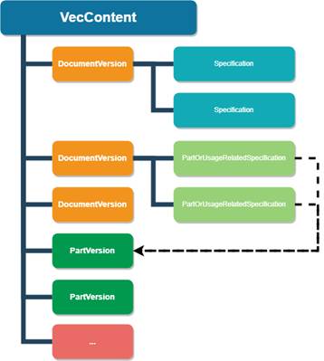
Figure 3 – Basic Structure of VEC Data
A 7:PartVersion in VEC is a unique identifier for a specific version/revision of a part. In VEC terms, a part is essentially anything that is used in the product or is created during production (a part can be composed of instances of other parts). This means that a 7:PartVersion in VEC applies to both the Part and Article in terms of this Companion Specification.
The term DocumentVersion goes back to the roots of VEC in the STEP standard and the document-oriented product development that prevailed at that time. In fact, DocumentVersion in the VEC stands for any piece of information or a data set that is clearly identifiable and whose changes can be tracked (e.g., a certain state of the properties of a connector, a terminal or a wire [Parts in this Companion Specification], or the definition of a lead set [Article in this Companion Specification]).
The content of a DocmentVersion is used to describe 7:PartVersions. They are represented by individual entities for the following reasons:
- In general, a document can describe multiple parts at same time, whereas a part can also be described by multiple documents (e.g., a data sheet, a drawing, a 3D model).
- Both can evolve independently, so tracking of changes & revisions must also be tracked inidividually (e.g., the data for a component can change without changing the physical component).
For example, in the context of this Companion Specification, this could mean that if a machine is sent a new 7:PartVersion, the input material has changed physically and the machine needs to be re-equipped for this new material. However, if only the content of a DocumentVersion changes, the same material processed, just in a different way.
The 7:PartVersion and DocumentVersion is a generic concept for tracking hardware and information changes. The information is described using specific subtypes of Specifications within a DocumentVersion.
Every subset of the VEC model that defines a specific aspect of the product has its own Specification; for example, a connector is described by a ConnectorHousingSpecification, a terminal by TerminalSpecification, etc. The same applies for more complex aspects of the article definition; e.g., the bill of materials is defined with a PartStructureSpecification, the contacting of wire ends with terminals with a ContactingSpecification, the basic structure of a wiring harness or leadset by a TopologySpecification, the geometric form by a BuildingBlockSpecification3D, etc.
Parts and Articles within this Companion Specification are composed of structures from two distinct sources: the ISA-95 Material Model from ISA95, which is intended for generic use, and the domain-specific VEC (Vehicle Electric Container) model. As these have both been integrated within this Companion Specification, Part and Article always consist of two segments: the generic component derived from the ISA-95 model, and the wire harness-specific element from the VEC model.
When adding a Parts, Article, or Job, it must be fully described and only reference existing elements. For example, when a new Job is added, it must reference already existing Parts and Articles within the system. When deleting elements, the integrity of the remaining data must not be compromised. This means the system must always ensure there are no references to missing or not yet transferred elements. For instance, if an Article is deleted, the system must verify that no existing Jobs reference this Article to maintain data consistency.
The wire harness industry is characterized by a series of specialized and critical processes that ensure the production of high-quality and functional wire harnesses. These processes are integral to the manufacturing flow and are carefully designed to meet precise design requirements.
This section provides an overview of the relevant processes covered by this Companion Specification:
Affixing metal connectors to wires with a tight deformation.
Cutting wires to specific lengths.
Applying protective materials to connections.
Longitudinal slitting of insulation along the wire.
Removing insulation from wire ends in preparation for connection via crimping or soldering.
The following is an overview of the categories of materials that are supported in this Companion Specification:
Provides the physical structure to support and protect connectors and wires, often made from durable plastics or metals.
The component within a connector where the wire is attached, which can be designed for crimping, soldering, or other types of connections.
Materials used to prevent moisture, dust, and other environmental contaminants from affecting the connections and components within the harness.
Flexible, often tubular, material that is used to bundle, protect, and insulate wires within the harness, available in various materials for different protective qualities.
A conductor, usually covered with an insulating material, that is used for carrying electrical current or signals.
There are multiple categories of wire harness manufacturing machines, each with different capabilities. Yet many of them have a local data store to keep part, spec and article information. This means that there are multiple ways to send part, article and job information to a machine.
Job Management is based on ISA95 and Machinery Job Control. This section provides some examples for use in a wire harness. These examples illustrate the concept with consideration of domain-specific aspects, such as different ways to transfer data.
Other workflows, or a mix of these examples is also possible. This example also represents a simplified version of the model.
In general, it is important that all information needed for the process is available beforehand. This means that a job can only be stored if the article spec is available (or sent with the job). Likewise, the article spec can only be stored if the part information is already available (or sent with the article spec). Thus, the model does not further restrict the base specifications. Some aspects are not shown in this example.
Parts of the original model are omitted for illustrative purposes.
This section describes a variant of the standardized workflow (other variants are possible) to store a Job within the framework of the Wire Harness Companion Specification, exemplified by the sequence diagrams in Figure 4. In this example, the part and article spec are stored on the machine before the Job is stored. The Part and Article can be stored via OPC UA (right side) or in another way, such as with a local HMI (left side).
Figure 4 – Example Sequence for Job Workflow with separate Part and Article Management
The workflow begins with the MES, which serves as the central control system overseeing the manufacturing operations, communicating with the MachineryItem responsible for executing the job:
Add Parts: The process initiates with the MES instructing the machine to add individual parts required for the job. In this case, 'Add Part 1,' 'Add Part 2,' and 'Add Part 3' are sequential steps that involve the MES sending commands to the machine to prepare the necessary components.
Add Article: After the parts are prepared, the MES instructs the machine to add 'Article A,' which is based on the assembly or combination of Parts 1-3. The article represents the blueprint or design specification for the final product.
StoreAndStartJob: With the parts and article prepared, the MES sends a StoreAndStartJob command. This includes the ArticleSpec and a directive to execute a set number of runs, which in this example is 10. This command effectively stores the job data and triggers the start of the production run.
Process Results: As the machine begins processing, it sends the results to the MES. These include 'Result Process A Run 1,' representing the outcome of the first run of process A, through 'Result Process m Run n,' denoting subsequent processes and runs. These results provide insight into the execution of each job run.
Job Result (KPI Details): Finally, after the job runs are completed, the machine sends a detailed report of the job results back to the MES. This report includes Key Performance Indicator (KPI) details, which are crucial for evaluating the efficiency and quality of the job execution.
The sequence diagram in Figure 5 depicts a streamlined process for initiating a job on a wire harness machine. Unlike the previous example, where parts and article information were added in separate steps, this approach consolidates the workflow by sending all necessary information along with the job creation command.
StoreAndStartJob: The MES sends a single StoreAndStartJob command to the machine. This command is comprehensive, containing all necessary data required for the job: 'ArticleSpec A,’ ‘Part 1-3,’ additional process input data, and the number of runs, which is set to 10 in this scenario. This encapsulation of data reduces the number of communication steps between the MES and the machine, leading to a more streamlined operation.
Processing and Feedback: As the job starts, the machine processes the information and begins the manufacturing runs. Feedback is then provided to the MES after each process is executed:
Result Process A Run 1: Details from the first run of Process A are sent back to the MES.
Result Process m Run n: As subsequent processes are completed, their results are also reported back to the MES in real time.
Job Result (KPI Details): At the conclusion of the job, a comprehensive report including KPI details is transmitted to the MES. These KPIs provide valuable insights into the performance, efficiency, and quality of the executed job.
Figure 5 – Example Sequence for Job Workflow without separate Part and Article Management
OPC UA is an open and royalty free set of standards designed as a universal communication protocol. While there are numerous communication solutions available, OPC UA has key advantages:
- A state of art security model (see OPC 10000-2).
- A fault tolerant communication protocol.
- An information modelling framework that allows application developers to represent their data in a way that makes sense to them.
OPC UA has a broad scope which delivers for economies of scale for application developers. This means that a larger number of high-quality applications at a reasonable cost are available. When combined with semantic models such as Wire Harness Manufacturing, OPC UA makes it easier for end users to access data via generic commercial applications.
The OPC UA model is scalable from small devices to ERP systems. OPC UA Servers process information locally and then provide that data in a consistent format to any application requesting data - ERP, MES, PMS, Maintenance Systems, HMI, Smartphone or a standard Browser, for examples. For a more complete overview see
OPC 10000-1.
As an open standard, OPC UA is based on standard internet technologies, like TCP/IP, HTTP, Web Sockets.
As an extensible standard, OPC UA provides a set of Services (see OPC 10000-4) and a basic information model framework. This framework provides an easy manner for creating and exposing vendor defined information in a standard way. More importantly all OPC UA Clients are expected to be able to discover and use vendor-defined information. This means OPC UA users can benefit from the economies of scale that come with generic visualization and historian applications. This specification is an example of an OPC UA Information Model designed to meet the needs of developers and users.
OPC UA Clients can be any consumer of data from another device on the network to browser based thin clients and ERP systems. The full scope of OPC UA applications is shown in Figure 6.
Figure 6 – The Scope of OPC UA within an Enterprise
OPC UA provides a robust and reliable communication infrastructure having mechanisms for handling lost messages, failover, heartbeat, etc. With its binary encoded data, it offers a high-performing data exchange solution. Security is built into OPC UA as security requirements become more and more important especially since environments are connected to the office network or the internet and attackers are starting to focus on automation systems.
OPC UA provides a framework that can be used to represent complex information as Objects in an AddressSpace which can be accessed with standard services. These Objects consist of Nodes connected by References. Different classes of Nodes convey different semantics. For example, a Variable Node represents a value that can be read or written. The Variable Node has an associated DataType that can define the actual value, such as a string, float, structure etc. It can also describe the Variable value as a variant. A Method Node represents a function that can be called. Every Node has a number of Attributes including a unique identifier called a NodeId and non-localized name called as BrowseName. An Object representing a ‘Reservation’ is shown in Figure 7.
Figure 7 – A Basic Object in an OPC UA Address Space
Object and Variable Nodes represent instances and they always reference a TypeDefinition (ObjectType or VariableType) Node which describes their semantics and structure. Figure 8 illustrates the relationship between an instance and its TypeDefinition.
The type Nodes are templates that define all of the children that can be present in an instance of the type. In the example in Figure 8 the PersonType ObjectType defines two children: First Name and Last Name. All instances of PersonType are expected to have the same children with the same BrowseNames. Within a type the BrowseNames uniquely identify the children. This means Client applications can be designed to search for children based on the BrowseNames from the type instead of NodeIds. This eliminates the need for manual reconfiguration of systems if a Client uses types that multiple Servers implement.
OPC UA also supports the concept of sub-typing. This allows a modeller to take an existing type and extend it. There are rules regarding sub-typing defined in OPC 10000-3, but in general they allow the extension of a given type or the restriction of a DataType. For example, the modeller may decide that the existing ObjectType in some cases needs an additional Variable. The modeller can create a subtype of the ObjectType and add the Variable. A Client that is expecting the parent type can treat the new type as if it was of the parent type. Regarding DataTypes, subtypes can only restrict. If a Variable is defined to have a numeric value, a sub type could restrict it to a float.
Figure 8 – The Relationship between Type Definitions and Instances
References allow Nodes to be connected in ways that describe their relationships. All References have a ReferenceType that specifies the semantics of the relationship. References can be hierarchical or non-hierarchical. Hierarchical references are used to create the structure of Objects and Variables. Non-hierarchical are used to create arbitrary associations. Applications can define their own ReferenceType by creating subtypes of an existing ReferenceType. Subtypes inherit the semantics of the parent but may add additional restrictions. Figure 9 depicts several References, connecting different Objects.
Figure 9 – Examples of References between Objects
The above figures utilize a notation that was developed for the OPC UA specification. The notation is summarized in Figure 10. UML representations can also be used; however, the OPC UA notation is less ambiguous because there is a direct mapping from the elements in the figures to Nodes in the AddressSpace of an OPC UA Server.
Figure 10 – The OPC UA Information Model Notation
A complete description of the different types of Nodes and References can be found in OPC 10000-3 and the base structure is described in OPC 10000-5.
OPC UA specification defines a very wide range of functionality in its basic information model. It is not required that all Clients or Servers support all functionality in the OPC UA specifications. OPC UA includes the concept of Profiles, which segment the functionality into testable certifiable units. This allows the definition of functional subsets (that are expected to be implemented) within a companion specification. The Profiles do not restrict functionality, but generate requirements for a minimum set of functionality (see OPC 10000-7)
OPC UA allows information from many different sources to be combined into a single coherent AddressSpace. Namespaces are used to make this possible by eliminating naming and id conflicts between information from different sources. Each namespace in OPC UA has a globally unique string called a NamespaceUri which identifies a naming authority and a locally unique integer called a NamespaceIndex, which is an index into the Server's table of NamespaceUris. The NamespaceIndex is unique only within the context of a Session between an OPC UA Client and an OPC UA Server- the NamespaceIndex can change between Sessions and still identify the same item even though the NamespaceUri's location in the table has changed. The Services defined for OPC UA use the NamespaceIndex to specify the Namespace for qualified values.
There are two types of structured values in OPC UA that are qualified with NamespaceIndexes: NodeIds and QualifiedNames. NodeIds are locally unique (and sometimes globally unique) identifiers for Nodes. The same globally unique NodeId can be used as the identifier in a node in many Servers – the node's instance data may vary but its semantic meaning is the same regardless of the Server it appears in. This means Clients can have built-in knowledge of of what the data means in these Nodes. OPC UA Information Models generally define globally unique NodeIds for the TypeDefinitions defined by the Information Model.
QualifiedNames are non-localized names qualified with a Namespace. They are used for the BrowseNames of Nodes and allow the same names to be used by different information models without conflict. TypeDefinitions are not allowed to have children with duplicate BrowseNames; however, instances do not have that restriction.
An OPC UA Companion Specification for an industry-specific vertical market describes an Information Model by defining ObjectTypes, VariableTypes, DataTypes and ReferenceTypes that represent the concepts used in the vertical market. It may also potentially describe well-defined Objects as entry points into the AddressSpace.