The standardization and depiction of the wire harness machinery rely on several fundamental building blocks, namely:
- Identification
- ItemState
- ApplicationMode
- Job Management
- Result Management
In this sector-specific adaptation, both Job Management and Result Management are extended to meet unique industry needs, while the other building blocks are incorporated unchanged.
Figure 1 illustrates the schematic structure of a job in the wire harness domain and its interplay with the results and the actual assets involved.
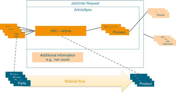
Figure 1 – Abstract overview of a Wire Harness Job
To execute, or run a job, multiple parts are supplied to the machine and processed into products. A product aligns with a specification, referred to as 'ArticleSpec.' An ArticleSpec contains process information, article information, and a reference to the parts used (“Part info“ in the above image). Additionally, measurement results may be captured by the machine or the machine operator during setup and production. During setup, a set of verification measurements may be gathered that apply to the entire production lot. During production, a set of monitoring measurements may be collected for each item produced. The set of validation and monitoring processes are part of the article specification. These are understood within this specification to be processed on an instance-dependent basis. Each job can also have additional status information, which is stored in the Job Response (see OPC UA 40001-1).
The Vehicle Electric Container (VEC) is a standardized data model that facilitates the exchange, collaboration, and archiving of electrical network, wiring harness and wiring harness component information in the automotive industry. It serves as a tool-independent digital representation of a vehicle's electrical system, supporting the conceptualization and design of logical mockups, the exchange of component data or the product specification of wiring harnesses. The VEC helps ensure traceability throughout the lifecycle of a vehicle's electrical system.
Developed under the guidance of the VDA and the prostep ivip Association, VEC is a standard in the automotive industry, and is published as VDA 4968 and PSI21.
Note: The complete VEC standard can be found here: https://ecad-wiki.prostep.org/specifications/vec/
This Companion Specification utilizes subsets of the VEC data model for the description of 'Article' and 'Part' information (see Figure 2). There are multiple reasons for this:
- It enhances interoperability and consistency in the exchange of data across different systems and equipment within the automotive industry. Article and Part information is used throughout the process, not only in communication with production machines.
- Components for the wiring harness (Parts) and the wiring harness itself (Article) are diverse, with great variety and many facets. Reusing vetted modelling concepts for their description increases the quality of these aspects for this Companion Specification and enables accelerated and efficient definitions.
- It allows this Companion Specification to focus on the additional aspects that are relevant to machine communication, such as job management, result data and process parameters.
Due to its scope as a common language in the wiring harness value chain, the VEC standard includes modelling concepts that are necessary in the design and engineering process, but not during production or for certain machine types (e.g., system schematics). The data model elements used in this Companion Specification are a subset of the complete data model defined by the VEC standard.
Concrete mapping between VEC and OPC UA is described in section 9.
Figure 2 – VEC as Part of the Job Description
The key concepts of the VEC are DocumentVersion and 7:PartVersion (see Figure 3).
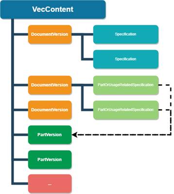
Figure 3 – Basic Structure of VEC Data
A 7:PartVersion in VEC is a unique identifier for a specific version/revision of a part. In VEC terms, a part is essentially anything that is used in the product or is created during production (a part can be composed of instances of other parts). This means that a 7:PartVersion in VEC applies to both the Part and Article in terms of this Companion Specification.
The term DocumentVersion goes back to the roots of VEC in the STEP standard and the document-oriented product development that prevailed at that time. In fact, DocumentVersion in the VEC stands for any piece of information or a data set that is clearly identifiable and whose changes can be tracked (e.g., a certain state of the properties of a connector, a terminal or a wire [Parts in this Companion Specification], or the definition of a lead set [Article in this Companion Specification]).
The content of a DocmentVersion is used to describe 7:PartVersions. They are represented by individual entities for the following reasons:
- In general, a document can describe multiple parts at same time, whereas a part can also be described by multiple documents (e.g., a data sheet, a drawing, a 3D model).
- Both can evolve independently, so tracking of changes & revisions must also be tracked inidividually (e.g., the data for a component can change without changing the physical component).
For example, in the context of this Companion Specification, this could mean that if a machine is sent a new 7:PartVersion, the input material has changed physically and the machine needs to be re-equipped for this new material. However, if only the content of a DocumentVersion changes, the same material processed, just in a different way.
The 7:PartVersion and DocumentVersion is a generic concept for tracking hardware and information changes. The information is described using specific subtypes of Specifications within a DocumentVersion.
Every subset of the VEC model that defines a specific aspect of the product has its own Specification; for example, a connector is described by a ConnectorHousingSpecification, a terminal by TerminalSpecification, etc. The same applies for more complex aspects of the article definition; e.g., the bill of materials is defined with a PartStructureSpecification, the contacting of wire ends with terminals with a ContactingSpecification, the basic structure of a wiring harness or leadset by a TopologySpecification, the geometric form by a BuildingBlockSpecification3D, etc.
Parts and Articles within this Companion Specification are composed of structures from two distinct sources: the ISA-95 Material Model from ISA95, which is intended for generic use, and the domain-specific VEC (Vehicle Electric Container) model. As these have both been integrated within this Companion Specification, Part and Article always consist of two segments: the generic component derived from the ISA-95 model, and the wire harness-specific element from the VEC model.
When adding a Parts, Article, or Job, it must be fully described and only reference existing elements. For example, when a new Job is added, it must reference already existing Parts and Articles within the system. When deleting elements, the integrity of the remaining data must not be compromised. This means the system must always ensure there are no references to missing or not yet transferred elements. For instance, if an Article is deleted, the system must verify that no existing Jobs reference this Article to maintain data consistency.
The wire harness industry is characterized by a series of specialized and critical processes that ensure the production of high-quality and functional wire harnesses. These processes are integral to the manufacturing flow and are carefully designed to meet precise design requirements.
This section provides an overview of the relevant processes covered by this Companion Specification:
Affixing metal connectors to wires with a tight deformation.
Cutting wires to specific lengths.
Applying protective materials to connections.
Longitudinal slitting of insulation along the wire.
Removing insulation from wire ends in preparation for connection via crimping or soldering.
The following is an overview of the categories of materials that are supported in this Companion Specification:
Provides the physical structure to support and protect connectors and wires, often made from durable plastics or metals.
The component within a connector where the wire is attached, which can be designed for crimping, soldering, or other types of connections.
Materials used to prevent moisture, dust, and other environmental contaminants from affecting the connections and components within the harness.
Flexible, often tubular, material that is used to bundle, protect, and insulate wires within the harness, available in various materials for different protective qualities.
A conductor, usually covered with an insulating material, that is used for carrying electrical current or signals.
There are multiple categories of wire harness manufacturing machines, each with different capabilities. Yet many of them have a local data store to keep part, spec and article information. This means that there are multiple ways to send part, article and job information to a machine.
Job Management is based on ISA95 and Machinery Job Control. This section provides some examples for use in a wire harness. These examples illustrate the concept with consideration of domain-specific aspects, such as different ways to transfer data.
Other workflows, or a mix of these examples is also possible. This example also represents a simplified version of the model.
In general, it is important that all information needed for the process is available beforehand. This means that a job can only be stored if the article spec is available (or sent with the job). Likewise, the article spec can only be stored if the part information is already available (or sent with the article spec). Thus, the model does not further restrict the base specifications. Some aspects are not shown in this example.
Parts of the original model are omitted for illustrative purposes.
This section describes a variant of the standardized workflow (other variants are possible) to store a Job within the framework of the Wire Harness Companion Specification, exemplified by the sequence diagrams in Figure 4. In this example, the part and article spec are stored on the machine before the Job is stored. The Part and Article can be stored via OPC UA (right side) or in another way, such as with a local HMI (left side).
Figure 4 – Example Sequence for Job Workflow with separate Part and Article Management
The workflow begins with the MES, which serves as the central control system overseeing the manufacturing operations, communicating with the MachineryItem responsible for executing the job:
Add Parts: The process initiates with the MES instructing the machine to add individual parts required for the job. In this case, 'Add Part 1,' 'Add Part 2,' and 'Add Part 3' are sequential steps that involve the MES sending commands to the machine to prepare the necessary components.
Add Article: After the parts are prepared, the MES instructs the machine to add 'Article A,' which is based on the assembly or combination of Parts 1-3. The article represents the blueprint or design specification for the final product.
StoreAndStartJob: With the parts and article prepared, the MES sends a StoreAndStartJob command. This includes the ArticleSpec and a directive to execute a set number of runs, which in this example is 10. This command effectively stores the job data and triggers the start of the production run.
Process Results: As the machine begins processing, it sends the results to the MES. These include 'Result Process A Run 1,' representing the outcome of the first run of process A, through 'Result Process m Run n,' denoting subsequent processes and runs. These results provide insight into the execution of each job run.
Job Result (KPI Details): Finally, after the job runs are completed, the machine sends a detailed report of the job results back to the MES. This report includes Key Performance Indicator (KPI) details, which are crucial for evaluating the efficiency and quality of the job execution.
The sequence diagram in Figure 5 depicts a streamlined process for initiating a job on a wire harness machine. Unlike the previous example, where parts and article information were added in separate steps, this approach consolidates the workflow by sending all necessary information along with the job creation command.
StoreAndStartJob: The MES sends a single StoreAndStartJob command to the machine. This command is comprehensive, containing all necessary data required for the job: 'ArticleSpec A,’ ‘Part 1-3,’ additional process input data, and the number of runs, which is set to 10 in this scenario. This encapsulation of data reduces the number of communication steps between the MES and the machine, leading to a more streamlined operation.
Processing and Feedback: As the job starts, the machine processes the information and begins the manufacturing runs. Feedback is then provided to the MES after each process is executed:
Result Process A Run 1: Details from the first run of Process A are sent back to the MES.
Result Process m Run n: As subsequent processes are completed, their results are also reported back to the MES in real time.
Job Result (KPI Details): At the conclusion of the job, a comprehensive report including KPI details is transmitted to the MES. These KPIs provide valuable insights into the performance, efficiency, and quality of the executed job.
Figure 5 – Example Sequence for Job Workflow without separate Part and Article Management