The PartManagementType contains a list of parts, as well as methods to add and remove parts from the Server. It is formally defined in Table 30.
The system must also be capable of managing local deletions, assuming that parts and articles can be removed from the local database while still existing in a central repository.
In cases of incorrect referencing (e.g., a missing part or article), the server must throw an error.
Table 30 – PartManagementType definition
|
Attribute |
Value |
||||
|
BrowseName |
PartManagementType |
||||
|
IsAbstract |
False |
||||
|
References |
Node Class |
BrowseName |
DataType |
TypeDefinition |
Other |
|
Subtype of the BaseObjectType defined in the OPC10000-3; i.e., inherits the InstanceDeclarations of that Node. |
|||||
|
HasComponent |
Method |
ClearPart |
|
|
Mandatory |
|
HasComponent |
Variable |
Terminals |
3:ISA95MaterialDataType[] |
BaseDataVariableType |
Optional |
|
HasComponent |
Variable |
Seals |
3:ISA95MaterialDataType[] |
BaseDataVariableType |
Optional |
|
HasComponent |
Variable |
Sleeves |
3:ISA95MaterialDataType[] |
BaseDataVariableType |
Optional |
|
HasComponent |
Variable |
Wires |
3:ISA95MaterialDataType[] |
BaseDataVariableType |
Optional |
|
HasComponent |
Method |
StorePart |
|
|
Mandatory |
|
HasComponent |
Method |
FindPartsByType |
|
|
Optional |
|
Conformance Units |
|||||
|
WireHarness PartManagementType |
|||||
Each Part represents an 3:ISA95MaterialDataType with the Properties shown in Table 15 (VECPartVersion and VECDocumentVersion).
Both Properties (VECPartVersion and VECDocumentVersion) must not provide by the server in the part Lists (Terminals, Seals, Sleeves, Wires) but need to be sent from the client to the server (in the method calls).
The Fields especially of the VECDocumentVersion structure depend on the kind of process and the Part. Table 31 - Table 33 show which fields need to be filled for each Part. The table has four columns. The first column displays the VEC attribute, the second provides an additional commonly used name, followed by a description and an indication of whether the parameter is always required or optional. The VEC attribute can be a direct child of the specification or a child of a subelement; in the latter case, it is separated by a "/".
Wires contain Part information for all wires. Table 31 contains the fields that must be given for this Parameter.
Terminals contain Part information for all terminals. Table 32 contains the fields that must be given for this Parameter.
Seals contain Part information for all seals. Table 33 contains the fields that must be given for this Parameter.
|
Fields (VEC Attributes) |
Alternative Name |
Description |
Optional/Mandatory field |
|
WireElementSpecification/WireType |
WireType |
Defines the type of the wire. A wire must not have more than one type. This attribute allows more than one value because the same type can be expressed in multiple reference systems. WireType: Specifies a wire type. A wire type is always defined by a key value. Which wire type is meant by this key value is defined by a standard reference system.
|
Optional |
|
ConductorSpecification/CrossSectionArea |
CrossSection |
Specifies the cross-section area of the conductor (e.g., 0.5 mm²). The cross-section area is a nominal value, which refers to the conducting properties of the conductor normalized to the properties of a full material core. |
Mandatory |
|
CoreSpecification/OutsideDiameter |
ConductorDiameter |
Specifies the outside diameter of the core. |
Optional |
|
WireElementSpecification/OutsideDiameter |
IsoDiameter |
Specifies the outside diameter of the WireElement. |
Optional |
|
InsulationSpecification/BaseColor |
Color_1 |
Specifies the base color of the outer insulation. |
Optional |
|
InsulationSpecification/FirstIdentificationColor |
Color_2 |
Specifies the first identification color of the outer insulation. |
Optional |
|
InsulationSpecification/SecondIdentificationColor |
Color_3 |
Specifies the second identification color of the outer insulation. |
Optional |
Table 32 – Fields of a Terminal
|
Fields |
Alternative Name |
Description |
Optional/Mandatory field |
|
WireReceptionSpecification/CrimpConnectionLength |
OverallCrimpingLength |
Distance from the conductor tip (in the direction of the center of the wire) to the beginning of the terminal. Specifies the length of the crimp area, conductor, and insulation crimp (wire reception, see diagram "Terminal Dimensions"). |
Optional |
|
TerminalSpecification/OverallLength |
OverallTerminalLength |
Used to circumnavigate obstacles. Specifies the overall length the terminal. |
Optional |
|
WireReceptionSpecification/CoreCrimpDetails/Size/Width |
NominalCrimpWidth |
Defines the expected size of the crimp. The height is measured in the direction of the crimp opening. The width is measured orthogonal to the height and orthogonal to the main axis of the terminal |
Optional |
|
WireReceptionSpecification/CoreCrimpDetails/Size/Width/Tolerance |
NominalCrimpWidthRange |
Specifies the tolerance for the CrimpWidth |
Optional |
|
MaximalTerminalWidth |
Defines the bounding box of the part. BoundingBox: The bounding box is defined for the processed state of the component, as it appears in the finished product. Therefore, it is valid to use the bounding box as simplified geometry of the component for viewing or simple DMU operations. For correct 3D positioning, the bounding may require transformation of the coordinate system of the component (see LocalGeometrySpecification.BoundingBoxPositioning).
The bounding box defines the smallest cuboid (box) that can contain a described part completely. If a component has multiple variants, the bounding box is the smallest cuboid that can contain every variant, while maintaining the spatial orientation of the bounding box and component variants.
It is valid to use the BoundingBox to describe the dimensions of a component, even if not all dimensions are known (e.g., only length and width). However, it must be possible to transform such a partial bounding box into a complete bounding box by adding the missing dimensions. Used to circumnavigate obstacles.
The x,y,z coordinate of the Bouding Box are defined in the Figure 14.
|
Optional |
|
|
TerminalType |
For display purposes. |
Optional |
|
|
WireReceptionSpecification/InsulationDisplacementLength |
NominalStrippingLength |
Specifies the length of the insulation which must be stripped off to fit to this wire reception. This overrides stripping parameters such as StripStartPosition |
Optional |
|
WireReceptionSpecification/InsulationDisplacementLength/Tolerance |
NominalStrippingLengthRange |
Specifies the tolerance for the dimension. |
Optional |
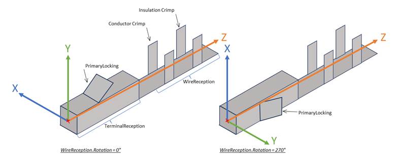
Figure 14 – Direction of a Terminal (based on VEC)
|
Fields |
Alternative Name |
Description |
Optional/Mandatory field |
|
GeneralTechnicalPartSpecification/ColorInformation |
SealColor |
Specifies the color of the part. |
Optional |
|
GeneralTechnicalPartSpecification/BoundingBox |
SealLength /GeometricSealWidth |
Length of the seal |
Mandatory |
This method is used to add a new Part to a list.
The signature of this Method is specified below. Table 34 and Table 35 specify the Arguments and AddressSpace representation, respectively.
Signature
StorePart(
[in]3:ISA95MaterialDataTypePart);
Table 34 – StorePart Method Arguments
|
Argument |
Description |
|
Part |
Information about the part. |
Table 35 – StorePart Method AddressSpace definition
|
Attribute |
Value |
||||
|
BrowseName |
StorePart |
||||
|
References |
NodeClass |
BrowseName |
DataType |
TypeDefinition |
ModellingRule |
|
0:HasProperty |
Variable |
0:InputArguments |
0:Argument[] |
0:PropertyType |
0:Mandatory |
This method returns all Parts of a Type.
The signature of this Method is specified below. Table 36 and Table 37 specify the Arguments and AddressSpace representation, respectively.
Signature
FindPartsByType (
[in]0:NodeId TypeNodeId,
[out]3:ISA95MaterialDataType[]Parts);
Table 36 – FindPartsByType Method Arguments
|
Argument |
Description |
|
TypeNodeId |
NodeId of the list of parts that should be returned. The node must be a subtype of the PartDataType. |
|
Parts |
Information about the part.
|
Table 37 – FindPartsByType Method AddressSpace definition
|
Attribute |
Value |
||||
|
BrowseName |
FindPartsByType |
||||
|
References |
NodeClass |
BrowseName |
DataType |
TypeDefinition |
ModellingRule |
|
0:HasProperty |
Variable |
0:InputArguments |
0:Argument[] |
0:PropertyType |
0:Mandatory |
|
0:HasProperty |
Variable |
0:OutputArguments |
0:Argument[] |
0:PropertyType |
0:Mandatory |
Theis method is used to remove a Part from the S.
The signature of this Method is specified below. Table 38 and Table 39 specify the Arguments and AddressSpace representation, respectively.
Note: The Data Integrity described in 4.1.3 must be considered.
Signature
ClearPart (
[in] 3:ISA95MaterialDataType Part);
Table 38 – ClearPart Method Arguments
|
Argument |
Description |
|
Part |
Information about the part. Either a MaterialClassID, or MaterialDefinitionID must be defined. Warning: If only the MaterialClassID is used, all entries of a MaterialClass (e.g., all wires) are cleared.
|
Table 39 – ClearPart Method AddressSpace definition
|
Attribute |
Value |
||||
|
BrowseName |
ClearPart |
||||
|
References |
NodeClass |
BrowseName |
DataType |
TypeDefinition |
ModellingRule |
|
0:HasProperty |
Variable |
0:InputArguments |
0:Argument[] |
0:PropertyType |
0:Mandatory |