The task of modelling an Asset is more than just describing a single simple Asset. It is modelling the relationships between the Assets. In OPC UA, relationships can be modelled as References, where a Reference provides semantic information about the relationship. OPC UA has defined a number of References in OPC 10000-23 that can be used for modelling Assets. This list is extended by this document. The following ReferenceTypes will be illustrated in various examples in this annex:
- HasContainedComponent indicates that an Asset has another Asset contained in it.
- HasBuiltInAsset indicates that an Asset has an integrated Asset, which is not removable.
- HasPart indicates that an Asset has another Asset which can be removed.
- HasAttachedComponent indicates that an Asset has physically/mechanically attached an Asset.
- IsPhysicallyConnectedTo (symmetric) indicates that two Assets are physically connected to each other.
- ConnectedTo (symmetric) indicates that two Assets are connected to each other by an electrical cable.
- IsPartOfRedundantAssetSet indicates that an Asset is part of a group of Assets that form a redundant Asset.
Additional References may be defined or used to show additional relationships.
Figure D.1 shows a simple single-board computer, in this case, a Raspberry Pi (“Raspberry Pi is a trademark of Raspberry Pi Ltd”), that can be modelled as an asset. This simple single-board computer has multiple items that can be modelled. It has many connector options, including extension boards or external devices and cables. The figure also includes a possible base asset model for the Raspberry Pi. This model does not include all features of a Raspberry Pi, but will be used to illustrate the available ReferenceTypes. This single-board computer could be modelled in many manners, and this illustrates just a possible model. Alternate models could exist and would not be wrong.
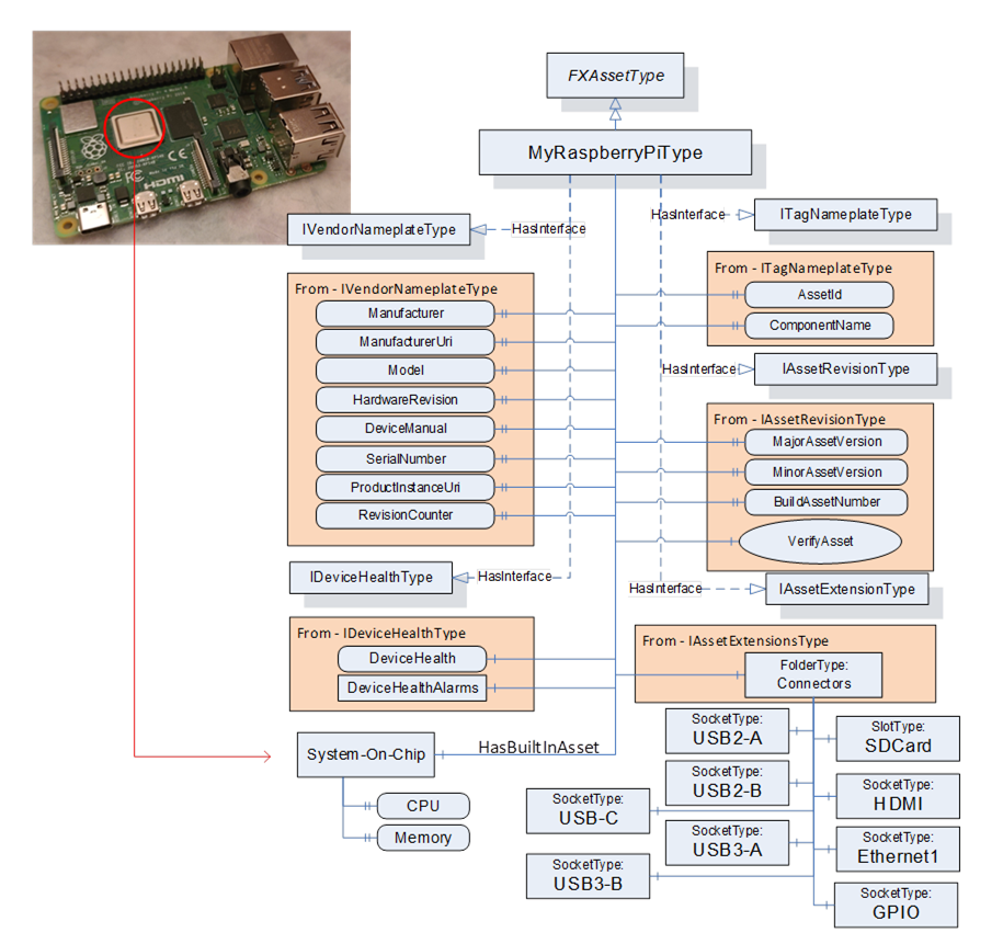
Figure D.1 – Raspberry Pi Asset type example
The MyRaspberryPiType is a subtype of FxAssetType. It mandates some of the Optional IVendorNameplateType Properties (all items listed), and it omits other Optional Properties from the interfaces that do not apply to MyRaspberryPiType. The model includes a number of Connectors that are used to add additional peripherals. The MyRaspberryPiType includes a System-On-Chip Object as an illustration of a HasBuiltInAsset. This Object contains information about the CPU and memory. It contains two Variables: one for the CPU Clock rate (can be 1.5 GHz or 1.8 GHz) that is used in the single board computer, and the other is an enumeration of the memory (can be 2, 4, or 8 GB).
The model does not include all the connectors that are available in a Raspberry Pi, but it does show the USB connectors and the external asset that is connected via a cable. See Figure D.2, showing the cable being attached to one of the USB ports. The figure also illustrates the resulting instance model. This figure only includes the instance information related to the ConnectedTo Reference; it does not include all of the other mandatory items that would be in the instance. The USB cable is represented by the ConnectedTo Reference. The Adaptor is its own Asset and might have its own configuration that is omitted here.
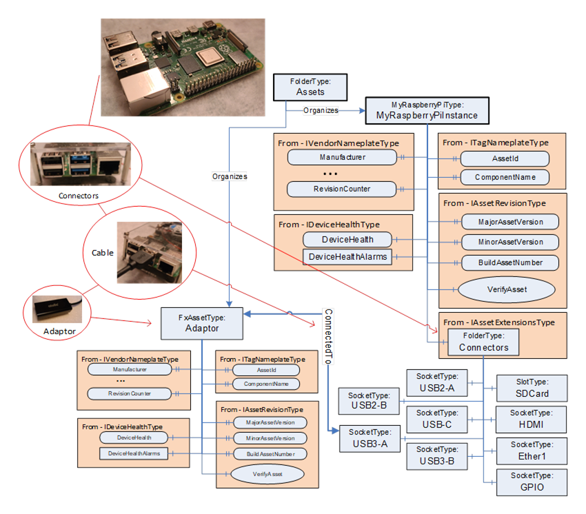
Figure D.2 – MyRaspberryPiType Instance with connection
The Raspberry Pi also has a slot for an SD card, which is also modelled (see Figure D.3). The SD card is visible from the outside and can be removed. It is modelled as a HasAttachedComponent. The SD card can also be updated; thus, the SD card model includes the optional SoftwareUpdate component. The SD card is not a top-level Asset, and thus, it does not implement the IDeviceHealthType interface.
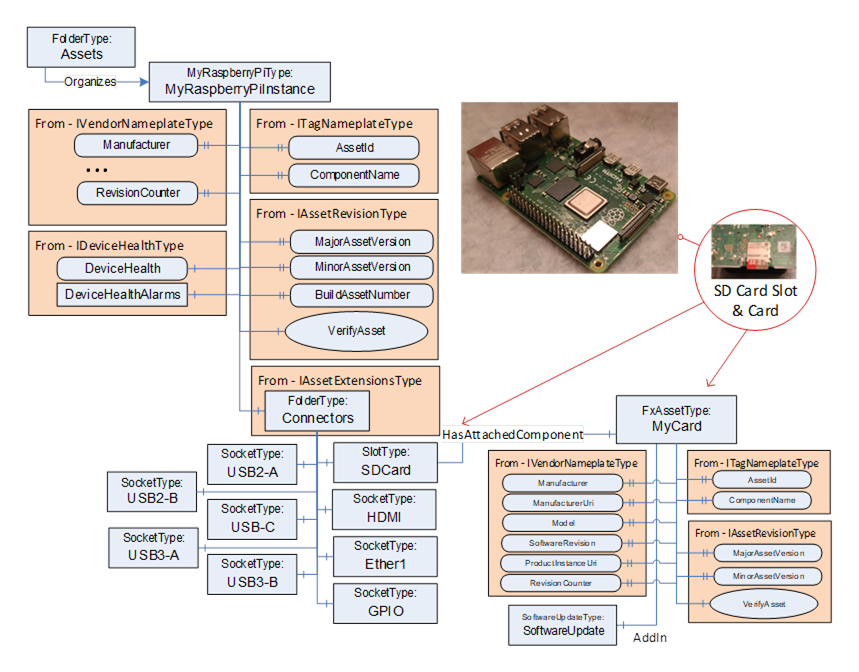
Figure D.3 – MyRaspberryPiType Instance with SD card Slot
An alternate manner in which the SD Card could have been modelled is illustrated in Figure D.4. This model does not show the slot since it is assumed that the card is always present. Vendors can generate multiple models, all of which are correct.
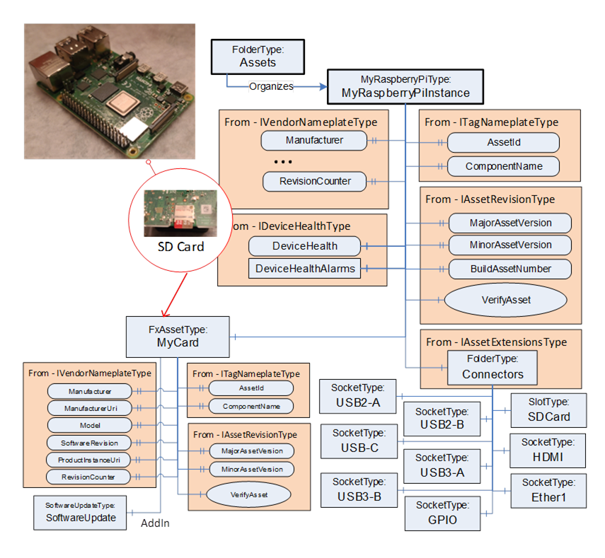
Figure D.4 – MyRaspberryPiType Instance with SD Card
The Raspberry Pi might also include extension boards such as the Sense HAT (see https://www.raspberrypi.com/products/sense-hat/ for more information) that is illustrated in Figure D.5. This removable type of extension board could be modelled using a HasPart Reference. In the resulting model, the SenseHat is not a top-level Asset but just a child of the GPIO connector that it is attached to. This addition provides a number of sensors – a gyroscope, accelerometer, magnetometer, humidity sensor, barometric sensor, temperature sensor and an LED display.
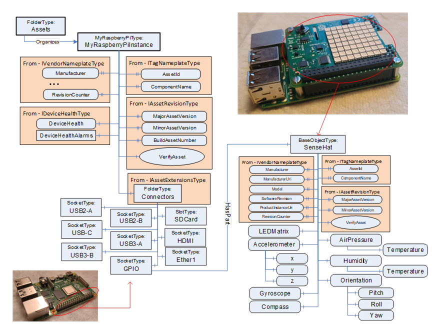
Figure D.5 – MyRaspberryPiType Instance with a Sensor Hat
The Raspberry Pi can also be enclosed in a case which also contains a fan (see Figure D.6). The fan is wired to the single-board computer. Both the Raspberry Pi and the fan are physically attached to the case. The case is not modelled as an Asset, but it can still make use of the References defined in OPC 10000-23.
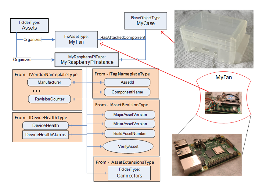
Figure D.6 – MyRaspberryPiInstance as part of larger model
Figure D.7 illustrates the entire Information Model for the Raspberry Pi described in this annex.
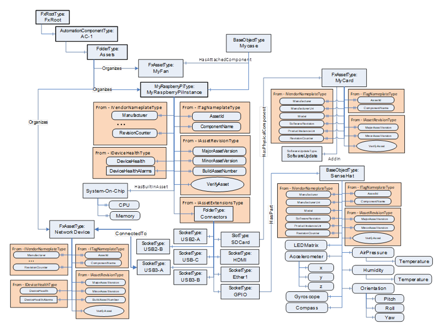
Figure D.7 – Raspberry Pi complete Asset model
Let’s look at a possible asset model for a rack into which controllers, power supplies and I/O modules are inserted. The rack may be cabled to an extension rack, where the extension rack holds additional I/O modules. The rack is illustrated in Figure D.8.
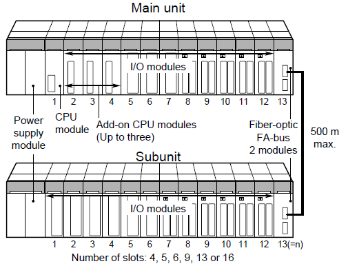
Figure D.8 – Rack based device illustration
This main rack could be modelled in a number of manners. Figure D.9 illustrates one possibility. The figure is not complete in that not all subcomponents or details are included. The model has a base rack model (MyRackType) that can represent any rack, including the Subunit. The base rack does include redundant power supplies. The main unit is modelled (MyMainRackType) as a subtype of this rack. The main unit includes a CPU, which is mandatory and always sits in Slot1.
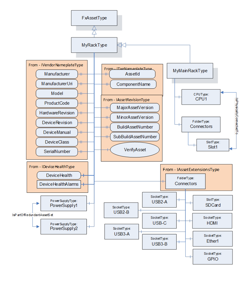
Figure D.9 – Rack model illustration
Figure D.10 illustrates the model for the CPU module. This model is based on interfaces and includes software update functionality. It also provides a variable that represents the temperature of the CPU (and the engineering units associated with the temperature). The CPU model also provides an enumeration that represents the status of the CPU module (Failed, Degraded, Normal). This status is used as an indicator light on the module.
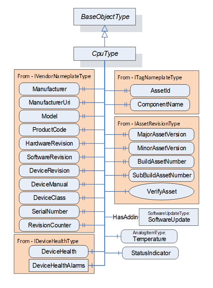
Figure D.10 – CPU Model illustration
Figure D.11 illustrates the IO Module model. This IOModuleType is a subtype of FxAssetType. The model includes a StatusIndicator that behaves exactly the same as the CPU Model StatusIndicator (Figure D.10). The model also supports software updates. The model includes a folder for connectors, where the connector provides connections to external IO. These connectors may be of any type, depending on the type of connected IO device. It is expected to be further subtyped. This model reflects specific types of external IO connections and devices.
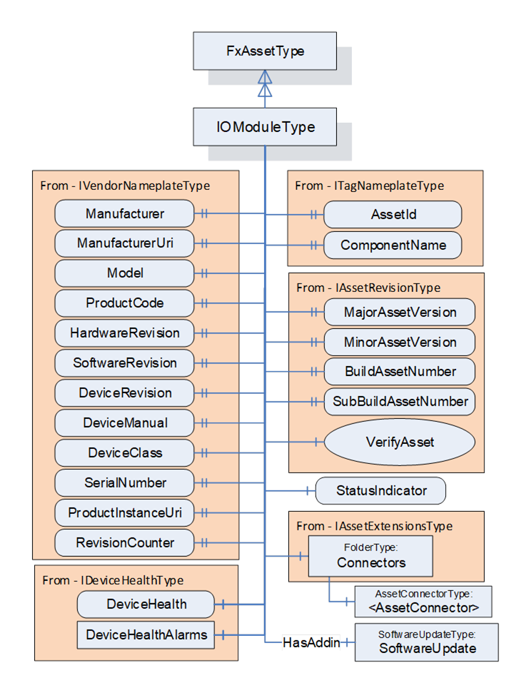
Figure D.11 – IO Model illustration
Figure D.12 illustrates the power supply module. This model is just a base object that exposes the required interfaces. The PowerSupplyType has a reduced set of IVendorNameplate properties. PowerSupplyType provides a Variable that reflects the power output of the supply. PowerSupplyType also has a variable that reflects the temperature. PowerSupplyType, as with all of the modules, includes a status indicator.
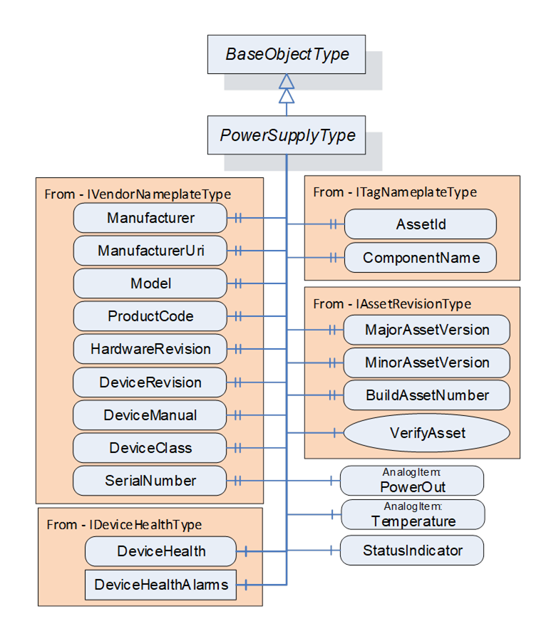
Figure D.12 – Power supply model illustration
Figure D.13 provides an illustration of a deployment of this model. The instance provides an additional CPU and includes several IO modules. The figure also illustrates the values of some of the variables in the various models. The figure omits many variables and values for simplicity. These variables would exist in the actual complete model. The model does not describe the devices that are connected to the IOP modules. This model is used for additional examples.
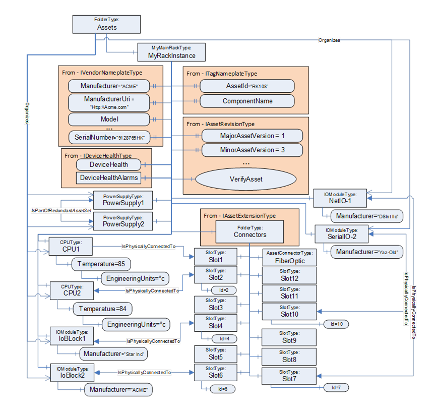
Figure D.13 – Instance of Rack example
A Client may verify whether an Asset meets the expectations of system engineering. This example demonstrates how to use verification. It uses the rack example.
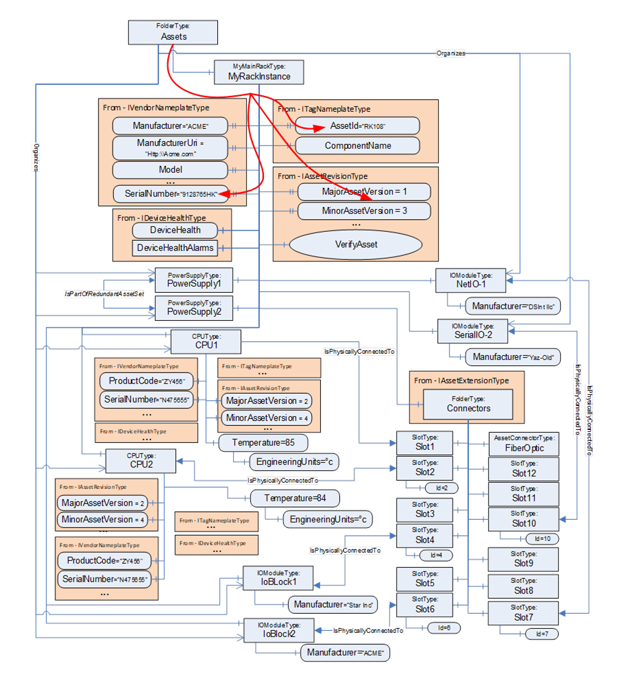
Figure D.14 – Sample for Assets of a chassis-based controller
Figure D.14 illustrates the Assets of a rack-based controller. The vendor modelled a 12-slot rack with Connectors, a communications module, and two controllers (CPU) modules. The IsPhysicallyConnectedTo Reference indicates that the modules are plugged into slots 1 & 2, whereas slot 3 is unused. IO modules are plugged into slot 4, slot 6, slot 7 and slot 10.
Assume that all CPU Assets are manufactured by the same manufacturer as the rack and have their ManufacturerUri set “http://ACME.com”.
Assume that the Descriptor contains for CPU1: ProductCode “ZY456”, MajorAssetVersion “2”, MinorAssetVersion”4”, and SerialNumber “N475655”, and for CPU2: ProductCode “YY544”, MajorAssetVersion “2”, MinorAssetVersion”7”, and SerialNumber “Z234545”.
A Client checking for compatibility of the Assets Controller1 and Controller2 by using VerificationMode AssetCompatibility will set the ExpectedVerificationVariables in VerifyAsset to the values as stated above, without the given SerialNumbers. The SerialNumbers should be added when using VerificationMode AssetIdentityAndCompatibility.
If the verified Assets match the expected values exactly, i.e., ManufacturerUri, ProductCode, MajorAssetVersion, and MinorAssetVersion are identical, Match will be returned. For example, if Controller2’s actual MinorAssetVersion is set to “9” but the Asset is still compatible with MinorAssetVersion “7”, Compatible will be returned.
The VerifyAsset Method allows doing additional verification besides verifying the Asset itself using ExpectedAdditionalVerificationVariables.
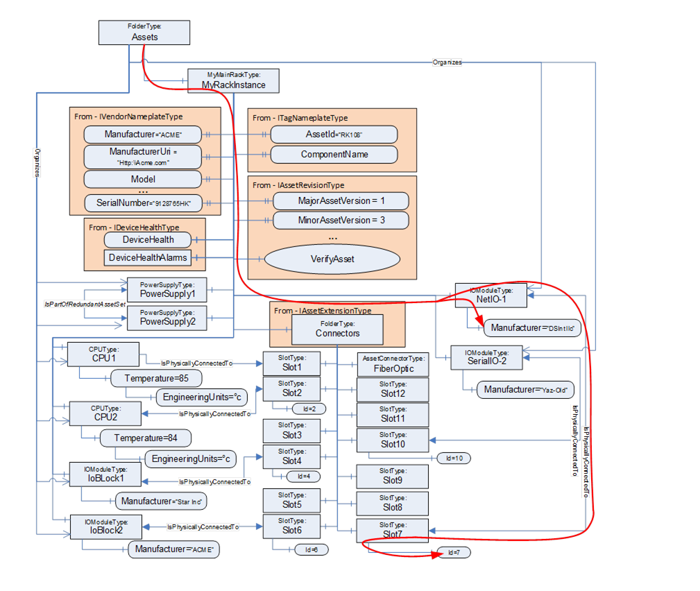
Figure D.15 – Asset Verification example – Asset location
Consider, for example, verifying whether an IOModule (NetIO-1) is plugged into Slot7. This can be done, as illustrated in Figure D.15, by using a relative path as:
<HasComponent>Assets
<Organizes>NetIO-1
<IsPhysicallyConnectedTo>Slot7
<HasVariable>Id
The Client can verify that NetIo-1 is physically connected to Slot7 by resolving this relative path. The VerifyAsset Method may now be used by the Client to verify that the resolved Node has a value of 7.
Figure D.16 – Verify Asset example – external device
This same concept can also be used to verify Assets that might not be directly linked to the AutomationComponent, i.e., they are not in the Assets folder but only referenced from existing Assets( see Figure D.16). In this example, the BrowsePath would look like:
<HasComponent>Assets
<Organizes>IoBlock2
<HasComponent>Connectors
<HasComponent>Slot1
<IsPhysicallyConnectedTo>DeviceX
This process could also be used to verify the values of configuration settings such as EngineeringUnits.