
9 System requirements (SafetyProvider and SafetyConsumer)
9.1 Constraints on the SPDU parameters
9.1.1 SafetyBaseID and SafetyProviderID
The pair of SafetyProviderID and SafetyBaseID is used by the SafetyConsumer to check the authenticity of the ResponseSPDU. SafetyProviderID and SafetyBaseID are usually assigned during engineering or during commissioning. It is in the responsibility of the end user or OEM to assign unique SafetyProviderID to individual SafetyProviders whenever this is reasonable possible. For instance, a machine builder should assign unique SafetyProviderIDs within a single machine containing multiple devices which run implementations of this document.
As the effort for the administration of unique SafetyProviderIDs will reach its limits when the system becomes large, this document uses the SafetyBaseID for cases where guaranteeing unique SafetyProviderIDs is not possible.
A SafetyBaseID is a universal unique identifier version4 (UUIDv4, also called globally unique identifier (GUID)), as described in ISO/IEC 9834-8:2014, Clause 15.It is a 128-bit number where at least 96 bits were chosen randomly. The probability that two randomly generated UUIDs are identical is extremely low (2-96 < 10-28), and can therefore be neglected, even when considering applications with a safety integrity level of 4.
It is not necessary to generate an individual SafetyBaseIDs for all SafetyProviders. If two SafetyProviders can be discriminated by their SafetyProviderIDs, they may share the same SafetyBaseID. For instance, a machine builder could generate a unique SafetyBaseID for each instance of a machine, which is reused for all SafetyProviders within a machine.
When implementing or using a generator for the UUIDs, it shall be ensured that each possible value is generated with equal probability (discrete uniform distribution), and that any two values are independent from each other. When a pseudo random number generator (PNRG) is used, it is ‘seeded’ with a random source having enough collision entropy (e.g. seeds of at least 128 bits that are uniformly distributed, too; and all seeds being pairwise independent from each other).
Most commercial systems offer random number generators for applications within a cryptographic context. These applications pose even harder requirements on the quality of random numbers than the ones mentioned above. Hence, cryptographically strong random number generators are applicable to this document as well. See References [2] to [5], as well as OPC 10000-2, for detailed information.
Table 38 shows implementations of cryptographically strong random number-generators that can be used to calculate the random part of the UUIDv4:
| Environment | Function |
|---|---|
| Microsoft® Windows® Operating Systems | BCryptGenRandom found in Bcrypt.dll |
| Unix®-like OS (e.g. Linux® / FreeBSD® / Solaris®) | Read from the file: /dev/urandom/ |
| .NET® | RandomNumberGenerator from System.Security.Cryptography |
| JavaScript® | Crypto.getRandomValues() |
| Java® | java.security.SecureRandom |
| Python® | os.urandom(size) |
While being evaluated from a security point of view, probably none of these implementations has been validated with safety in mind. Therefore, there is a remaining risk that these implementations are subject to systematic implementation errors which could decrease the effectiveness of these random numbers. To overcome this problem, the output of the random number generator is not used directly, but a SHA256-hash is calculated over (1) the generator’s output, (2) a timestamp (wall-clock-time or persistent logical clock) and (3) a unique domain name. Any bits of the SHA256-hash can then be used to construct the random parts of the UUIDv4.
[RQ9.1] The parameters SafetyBaseID and SafetyProviderID shall be stored in a non-volatile, i.e. persistent, way.
9.1.2 SafetyConsumerID
The SafetyConsumerID allows for discrimination between RequestSPDUs and ResponseSPDUs belonging to different SafetyConsumers. It is mainly used for diagnostic purposes, such as detecting unintentional concurrent access of a single SafetyProvider by multiple SafetyConsumers. Safety-related communication errors which are detected by checking the SafetyConsumerID would also be detected by other mechanisms, including the MNR, the SafetyProviderID, and the SafetyConsumerTimeout.
From a safety point of view, there are no qualitative requirements regarding the generation or administration of the SafetyConsumerID. It may be assigned during engineering, commissioning, at startup, and may even change during runtime. It is not required to check for uniqueness of SafetyConsumerIDs.
However, assigning identical SafetyConsumerIDs to multiple consumers is not recommended because fault localization can become more difficult.
9.2 Initialization of the MNR in the SafetyConsumer
The MNR is used to discriminate messages stemming from the same SafetyProvider and is therefore used to detect timeliness errors such as outdated messages, messages received out-of-order, or streams of messages erroneously repeated by a network storing element (e.g. a router).
To be effective, the set of used MNR values shall not be restricted to a small set. This could happen for connections which are restarted frequently, and which start counting from the same MNR value each time.
There are at least two ways to address this potential problem:
Option 1: [RQ9.2a] Whenever the connection is terminated, the current value of the MNR shall be safely stored within non-volatile memory of the SafetyConsumer. After restart, the previously stored MNR is used for initialization of the MNR (i.e. in state S12 of the SafetyConsumer state machine).
Option 2: [RQ9.2b] Whenever the SafetyConsumer is restarted (i.e. in state S12 of the SafetyConsumer state machine), the MNR is initialized with a 32-bit random number.
Either requirement RQ9.2a or requirement RQ9.2b, or an equivalent solution shall be fulfilled.
9.3 Constraints on the calculation of system characteristics
9.3.1 Probabilistic considerations (informative)
Following IEC 61784-3, this document detects all communication errors which can possibly occur in the underlying standard transmission system, including the OPC UA stack. If an error is detected, the erroneous data is discarded. Moreover, this document is designed in such a way that a safety function becomes practically unusable if the failure rate in the underlying, standard transmission system is higher than one error per safety error interval limit (6, 60, or 600 minutes), depending on the desired SIL of the safety function (see Table 26 and Table 39).
Thus, for operational safety functions a failure rate of 0,1 h-1, 1 h-1, or 10 h-1 can be assumed for communication errors occurring in the OPC UA stack. In order to obtain the communication’s contribution to the PFH value of the safety function, this value has to be multiplied by the so-called conditional residual error probability Pre,cond. For the CRC mechanism used in this document, it holds:
Pre,cond ≤ 4,0 × 10⁻¹⁰
This leads to the PFH and PFD values shown in Table 39.
The value 4,0 × 10⁻¹⁰ was justified by extensive numerical evaluation of the 32-bit CRC generator polynomial in use (0xF4ACFB13). The results of this evaluation, executed for all relevant data lengths and all relevant values for the bit error probability p up to p = 0,5, is shown in Figure 26. As can be seen, Pre,cond never exceeds the value 4,0 × 10⁻¹⁰.
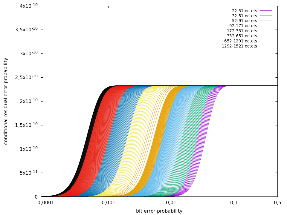
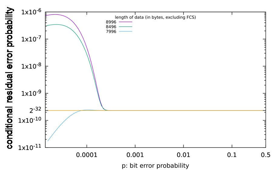
An explanation that it is indeed necessary to calculate Pre,cond for all data lengths and all relevant values of p can be found in Figure 27. For the data lengths shown in this figure, Pre,cond exceeds the desired value by several orders of magnitudes. The maximum value of Pre,cond is not obtained when p becomes maximal.
9.3.2 Safety related assumptions (informative)
The boundary conditions and assumptions for safety assessments and calculations of residual error rates are listed here.
Generally:
Number of retries in the underlying standard transmission system :
No restrictionsCRC polynomials used inside the underlying standard transmission system(e.g. Ethernet, TCP, …):
No restrictionsMessage storing elements:
No restrictions; any number of message storing elements is permittedSize of SafetyData within one ResponseSPDU:
≤ 1 500 octets
Even for safety functions that do not require manual operator acknowledgment for restart, manual operator acknowledgment is mandatory whenever the SafetyConsumer has detected certain types of errors and indicates this using OperatorAckRequested. Hence, operator acknowledgment is expected to be implemented by the safety application whenever OPC UA Safety is used. For details, see 6.3.4.3 and Clause B.2.
9.4 PFH and PFD values of a logical safety communication link
The PFH value of a logical safety communication link according to this document depends on the parameter of SafetyErrorIntervalLimit (see Table 26) of the link’s SafetyConsumer. Whenever the SafetyConsumer detects a mismatch of the SafetyConsumerID, SPDU_ID, MNR or CRC, it will only continue operating if the last occurrence of such an error happened more than SafetyErrorIntervalLimit time units ago. Otherwise, it will make a transition to fail-safe values, which can only be left by manual operator acknowledgment, see 6.3.4.3.
This directly limits the rate of detected errors, and indirectly limits the rate of undetected (residual) errors.
See Table 39 for numeric PFH and PFD values.
| SafetyErrorIntervalLimit | Allowed for SIL range | Total residual error rate for one logical connection of the safety function (PFH) | Total residual error probability for one logical connection of the safety function, for a mission time of 20 years (PFDavg) |
|---|---|---|---|
| 6 min | Up to SIL2 | < 4,0 × 10⁻⁹ / h | < 1,0 × 10⁻⁶ |
| 60 min | Up to SIL3 | < 4,0 × 10⁻¹⁰ / h | < 2,5 × 10⁻⁷ |
| 600 min | Up to SIL4 | < 4,0 × 10⁻¹¹ / h | < 8,0 × 10⁻⁸ |
The parameter SafetyErrorIntervalLimit affects either the PFH or the PFD, or both of only the safety communication channel. There is no effect on the PFH and PFD values of the components the SafetyProviders and SafetyConsumers are running on. The requirements for the implementation of these components are specified in the IEC 61508 series.
9.5 Safety manual
[RQ9.3] According to IEC 61508-2, the suppliers of equipment implementing an implementation of this document shall provide a safety manual. The instructions, information and parameters of Table 40 shall be included in that safety manual unless they are not relevant for a specific device.
| Item | Instruction or parameter | Remark | |
|---|---|---|---|
| 1 | Safety handling | Instructions on how to configure, parameterize, commission and test the device safely in accordance with the IEC 61508 series and IEC 61784-3. | |
| 2 | PFH, respectively PFDavg | The PFH, respectively PFDavg, per logical connection of the safety function. | See 9.3.2 and 9.4 |
| 3 | SFRTOPCSafety | Information on how this value can be calculated by the end user or OEM. | See 8.1 The implementation and error reaction of ConsumerCycleTime is in the responsibility of the either the vendor or the integrator, or both. |
| 4 | SafetyBaseID / SafetyProviderID | Information on how the SafetyBaseID and SafetyProviderID are generated and assigned. | See 9.1.1 |
| 5 | Commissioning | Either the end user or the OEM, or both, are responsible for verification and validation of correct cabling and assignment of network addresses. The safety manual shall address how this can be accomplished. | |
| 6 | Operator acknowledgment | If the SafetyConsumers makes a transition to fail-safe substitute values requiring operator acknowledgment “frequently”, this is an indication that a check of the installation (for example electromagnetic interference), network traffic load, or transmission quality is required. It shall be mentioned in the manual that it is potentially unsafe to simply omit these checks. – more than once per day in SIL2 and SIL3 applications – more than once per week in SIL4 applications | |
| 7 | High demand and low demand applications | The SafetyConsumer shall be executed cyclically within a shorter time frame than the SafetyConsumerTimeout. | |
| 8 | Maintenance | Specific requirements for device repair and device replacement. | |
| 9 | Relevant safety standards | A safety device according to this document shall fulfill the requirements of the relevant safety standards, such as the IEC 61508 series (according to the SIL as described) when used in live operation. | For usage in live operation |
9.6 Indicators and displays
[RQ9.4] The device a SafetyConsumer is running on shall be able to indicate if SAPI.OperatorAckRequested is enabled. This can be done for example by an indicator LED or by using an HMI.
[RQ9.5] If an LED is used for indication, it shall blink in green colour with frequency of 0,5 Hz whenever the output SAPI.OperatorAckRequested is true of at least one of the SafetyConsumers running on the device.
This LED may also be used for other purposes. For instance, normal operation may be indicated by a non-flashing LED, or erroneous behaviour may be indicated by an LED blinking with a frequency higher than 0,5 Hz. Thus, this document does not contain any requirements for the behaviour of the LED if SAPI.OperatorAckRequested is false.
The message shown on an HMI is application-specific. For instance, the text “machine has stopped for safety reasons. For restart, please check for obstacles and press the green button.” can be shown.