Figure 13 shows the structure of a RequestSPDU which originates at the SafetyConsumer and contains a SafetyConsumerID, a MonitoringNumber (MNR), and one byte of (non-safety-related) flags (Flags).
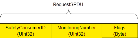
NOTE: The RequestSPDU does not contain a CRC-checksum.
Figure 14 shows the structure of a ResponseSPDU which originates at the SafetyProvider and contains the safety data (1 – 1500 Byte) and additional 25 Byte safety code (STrailer) as described in the subsequent sections, and the non-safety related data.
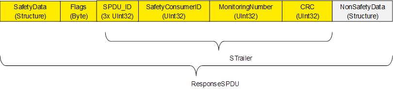
NOTE: In order to avoid spurious trips, the ResponseSPDU is transmitted in an atomic (consistent) way from the OPC UA platform interface of the SafetyProvider to the OPC UA platform interface of the SafetyConsumer. This is the task of the respective OPC UA mapper, see Figure 2.
Identifier of the SafetyConsumer instance, for diagnostic purposes, see Clause 11.1.2.
The SafetyConsumer uses the MNR to detect mis-timed SPDUs, e.g. such SPDUs which are continuously repeated by an erroneous network storing element. A different MNR is used in every RequestSPDU of a given SafetyConsumer, and a ResponseSPDU will only be accepted, if its MNR is identical to its matching RequestSPDU.
The checking for correctness of the MNR is performed by the SafetyConsumer, only.
[RQ8.1] The flags of the Safety Consumer (RequestSPDU.Flags) shall be used as shown in Table 18.
Table 18 – Structure of RequestSPDU.Flags
|
Bit nr. |
Identifier |
Description |
|
LSB = Bit 0 |
CommunicationError |
0: No error 1: An error was detected in the previous ResponseSPDU. |
|
Bit 1 |
OperatorAckRequested |
Used to inform the SafetyProvider that operator acknowledgment is requested. |
|
Bit 2 |
FSV_Activated |
Is used for conformance test of SafetyConsumer.SAPI.FSV_Activated |
|
Bit 3......7 |
Reserved for future use |
Always set to zero, not evaluated. |
NOTE: CommunicationError can be used as a trigger, e.g. for a communication analysis tool.
Flags reserved for future use shall be set to zero by the SafetyConsumer and shall not be evaluated by the SafetyProvider.
[RQ8.2] SafetyData shall contain the safety-related application data transmitted from the SafetyProvider to the SafetyConsumer. It may comprise multiple basic OPC UA variables (see Clause 6.4). For the sake of reducing distinctions of cases, SafetyData shall always be a structure, even if it contains a single basic OPC UA variable, only.
For the calculation of the CRC Signature, the order in which this data is processed by the calculation is important. SafetyProvider and SafetyConsumer must agree upon the number, type and order of application data transmitted in SafetyData. The sequence of SafetyData is fixed.
NOTE SafetyData may contain qualifier bits for a fine-grained activation of fail-safe substitute values. For a valid process value, the respective qualifier is set to 1 (good), whereas the value 0 (bad) is used for invalid values. Invalid process values are replaced by a fail-safe substitute value in the consumer’s safety application. See Clause 5.3.
[RQ8.3] The flags of the SafetyProvider (ResponseSPDU.Flags) shall be used as shown in Table 19.
Table 19 – Structure of ResponseSPDU.Flags
|
Bit nr. |
Name |
Description |
|
LSB = Bit 0 |
Operator acknowledgment at the provider, hereby forwarded to the SafetyConsumer, see OperatorAckProvider in the SAPI of the SafetyProvider, Clause 7.3.1. |
|
|
Bit 1 |
Activation of fail-safe values by the safety application at the SafetyProvider, hereby forwarded to the SafetyConsumer, see ActivateFSV in the SAPI of the SafetyProvider, Clause 7.3.1. |
|
|
Bit 2 |
Enabling and disabling of test mode in the SafetyProvider, hereby forwarded to the SafetyConsumer, see EnableTestMode in the SAPI of the SafetyProvider, Clause 7.3.1. |
|
|
Bit 3 ...... 7 |
Reserved for future use |
Always set to zero, not evaluated. |
[RQ8.4] Flags reserved for future use shall be set to zero by the SafetyProvider and shall not be evaluated by the SafetyConsumer.
This field is used by the SafetyConsumer to check whether the ResponseSPDU is coming from the correct SafetyProvider. For details, see Clause 8.1.3.1.
[RQ8.5] The SafetyConsumerID in the ResponseSPDU shall be a copy of the SafetyConsumerID received in the corresponding RequestSPDU. See Clause 8.1.3.1.
[RQ8.6] The MonitoringNumber in the ResponseSPDU shall be a copy of the MonitoringNumber received in the corresponding RequestSPDU. See Clause 8.1.3.1.
The SafetyConsumer uses the ResponseSPDU.MonitoringNumber to detect mis-timed SPDUs, e.g. such SPDUs which are continuously repeated by an erroneous network storing element. A different MonitoringNumber is used in every RequestSPDU of a given SafetyConsumer, and a ResponseSPDU will only be accepted, if its MonitoringNumber is identical to its matching RequestSPDU.
[RQ8.7] This CRC-checksum shall be used to detect data corruption. See Clause 8.1.3.5 on how it is calculated in the SafetyProvider and how it is checked in the SafetyConsumer.
[RQ8.8] This structure shall be used to transmit non-safety data values (e.g. diagnostic information) together with safe data consistently. Non-safety data is not CRC-protected and may stem from an unsafe source. [RQ8.9] When presented to the safety application (e.g. at an output of the SafetyConsumer), non-safety values shall clearly be indicated as “non-safety”, by an appropriate vendor-specific mechanism (e.g. by using a different color).
To avoid possible problems with empty structures, the dummy structure NonSafetyDataPlaceholder shall be used when no non-safety data is used.