Figure 9 gives an overview of the safety communication layer and its interfaces. It thereby also shows the scope of this part. The main function of the OPC UA Safety layer services is the state machine which handles the protocol. The state machines interact with the following interfaces:
- The Safety Application Program Interface (SAPI) is accessed by the safety application for exchanging safety data during runtime.
- The Safety Parameter Interface (SPI) is accessed during commissioning for setting safety parameters such as IDs or the timeout value in the SafetyConsumer.
- The non-safety related Diagnostics Interface (DI) can be accessed at runtime for troubleshooting the safety communication.
- the OPC UA platform interface (OPC UA PI) connects the SCL to the non-safe OPC UA stack and is used during runtime.
The interfaces (SAPI, SPI, DI and OPC UA PI) described in this clause are abstract and informative. They represent logical data inputs and outputs to this layer that are necessary for the proper operation of the state machine. No normative, concrete mappings are specified. The concrete implementations are vendor specific and may not exactly match the abstract interfaces described.
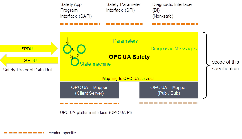
Figure 9 – Safety communication layer overview
The state machines of OPC UA Safety are independent from the actual OPC UA services used for data transmission. This is accomplished by introducing a so-called OPC UA Mapper, serving as an interface between the safety communication layer and the OPC UA stack.
This first version of the specification describes only a single mapper, which makes use of OPC UA client/server and remote method invocation
Figure 10 shows an overview of the SafetyProvider interfaces. The SAPI is specified in Clause 7.3.1, the SPI is specified in Clause 7.3.2.
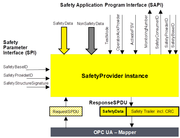
Figure 10 – SafetyProvider interfaces
[RQ7.1] The SAPI of the SafetyProvider represents the Safety communication layer services of the SafetyProvider. Table 13 lists all inputs and outputs of the SAPI of the SafetyProvider. Each SafetyProvider shall implement the SAPI as shown in Table 13, however, the details are vendor specific.
Table 13 – SAPI of the SafetyProvider
|
SAPI Term |
Type |
Definition |
|
Structure |
This input is used to accept the user data which is then transmitted as SafetyData in the SPDU. NOTE: Whenever a new MNR is received from a SafetyConsumer, the state machine of the SafetyProvider will read a new value of the SafetyData from its corresponding Safety Application and use it until the next MNR is received. NOTE: If no valid user data is available at the Safety Application, ActivateFSV is expected to be set to "1" by the Safety Application. |
|
|
Structure |
Used to consistently transmit non-safety data values (e.g. diagnostic information) together with safe data, see Clause 8.1.1.10 |
|
|
|
Boolean |
By setting this input to "1" the remote SafetyConsumer is informed (by Bit 2 in ResponseSPDU.Flags, see Table 19) that the SafetyData are test data, and is not to be used for safety related decisions. NOTE: The OPC UA Safety stack is intended for implementation in safety devices exclusively, see Clause 4.2. |
|
Boolean |
This input to is used to implement an operator acknowledgment on the provider side. The value will be forwarded to the consumer, where it can be used to trigger a return from fail-safe substitute values (FSV) to actual process values (PV), see Annex B.2.4.
|
|
|
ActivateFSV(Fail-safeSubstituteValues) |
Boolean |
By setting this input to "1" the SafetyConsumer is instructed (via Bit 1 in ResponseSPDU.Flags, see Table 19) to deliver FSV instead of PV to the safety application program. NOTE: If the replacement of process values by FSV should be controllable in a more fine-grained way, this can be realized by using qualifiers within the SafetyData, see Clause 5.3. |
|
UInt32 |
This output yields the ConsumerID used in the last access to this SafetyProvider by a SafetyConsumer see Clause 176.1.1. NOTE: all safety-related checks are executed by OPC UA Safety. The safety application is not required to check this SafetyConsumerID. |
|
|
UInt32 |
This output yields the monitoring number (MNR). It is updated whenever a new request comes in from the SafetyConsumer. NOTE: all safety-related checks are executed by OPC UA Safety. The safety application is not required to check this Monitoring number. |
|
|
UInt32 |
By changing this input to a non-zero-value, the SafetyProvider uses this variable instead of the SPI-Parameter SafetyProviderID. If it is changed to “0”, the parameter SafetyProviderID will become activated.See Figure 10, Clause 3.2.26, and Clause 11.1.1. |
|
|
GUID |
By changing this input to a non-zero-value, the SafetyProvider uses this variable instead of the SPI-Parameter SafetyBaseID. If it is changed to “0”, the parameter SafetyBaseID will become activated.See Figure 10, Clause 3.2.25, and Clause 11.1.1. |
[RQ7.2] Each SafetyProvider shall implement the parameters as shown in Table 11 which can be set via the SPI. The mechanisms for setting these parameters are vendor specific.
Table 14 – SPI of the SafetyProvider
|
Identifier |
Type |
Range |
Note |
|
SafetyBaseID |
GUID |
See GUID |
Base-ID of the SafetyProvider, which is normally used, see Clause 3.2.25. and Clause 11.1.1. For dynamic systems, the safety application program can overwrite this ID by providing a non-zero value at the input SafetyBaseID of the SafetyProvider’ s SAPI. |
|
SafetyProviderID |
UInt32 |
1 - 0xFFFFFFFF |
Provider-ID of the SafetyProvider, see Clause 3.2.26 and Clause 11.1.1. |
|
SafetyStructureSignature |
UInt32 |
1 – 0xFFFFFFFF |
Signature of the SafetyData structure, for calculation see Clause 8.1.3.4 |
[RQ7.3] Each SafetyProvider shall implement constants as shown in Table 12 whose values depend on the way the SafetyProvider is implemented. They never change and are therefore not writable via any of the interfaces. The constant SafetyProviderDelay has no influence on the functional behavior of the SafetyProvider. However, it will be provided in the OPC UA information model of a SafetyProvider to inform about its worst-case delay time. The value can be used during commissioning to check whether the timing behavior of the SafetyProvider is suitable to fulfill the watchdog delay of the corresponding SafetyConsumer.
Table 15 – Properties of SafetyProvider
|
Identifier |
Type |
Range |
Note |
|
SafetyProviderDelay |
UInt32 |
0x1 – 0xFFFFFFFF |
In microseconds (µs). It can be set in the engineering phase of the SafetyProvider or set during online configuration as well. SafetyProviderDelay is the maximum time at the SafetyProvider from receiving the RequestSPDU to start the transmission of ResponseSPDU, see Clause 10.2. |
|
SafetyProviderLevel |
Byte |
0x01 - 0x04 |
The maximal SIL the SafetyProvider implementation (hardware & software) is capable of, see Figure 11. It is used to inform the SafetyConsumer to parametrize the appropriate SafetyProviderLevel and then to generate the appropriate SafetyProviderLevel_ID.NOTE: It is independent from the generation of the SafetyData at SAPI. |
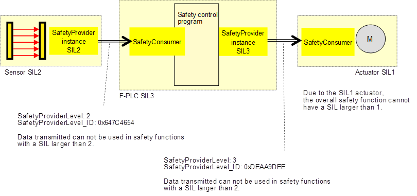
Figure 11 – Example combinations of SIL capabilities
The constant SafetyProviderLevel determines the value which is used for SafetyProviderLevel_ID when calculating the SPDU_ID, see Clause 8.1.3.3.
Note: SafetyProviderLevel is defined as the maximal SIL the SafetyProvider implementation (hardware & software) is capable of. It should not be confused with the SIL-level of the implemented safety function. For instance, Figure 11 shows a safety function which is implemented using a SIL2-capable sensor, a SIL3-capable PLC, and a SIL1-capable actuator. The overall SIL of the safety function is considered to be SIL1. Nevertheless, the SafetyProvider implemented on the sensor will use the constant value “2” as SafetyProviderLevel, whereas the SafetyProvider implemented on the PLC will use the constant value “3” as SafetyProviderLevel.
The respective SafetyConsumers (on the PLC and the actuator) need to know the SafetyProviderLevel of their providers for being able to check the SPDU_ID (see Clause 8.1.3.2).
The Figure 12 shows an overview of the SafetyConsumer interfaces. The SAPI is specified in Clause 7.4.1, the SPI is specified in Clause 7.4.3.
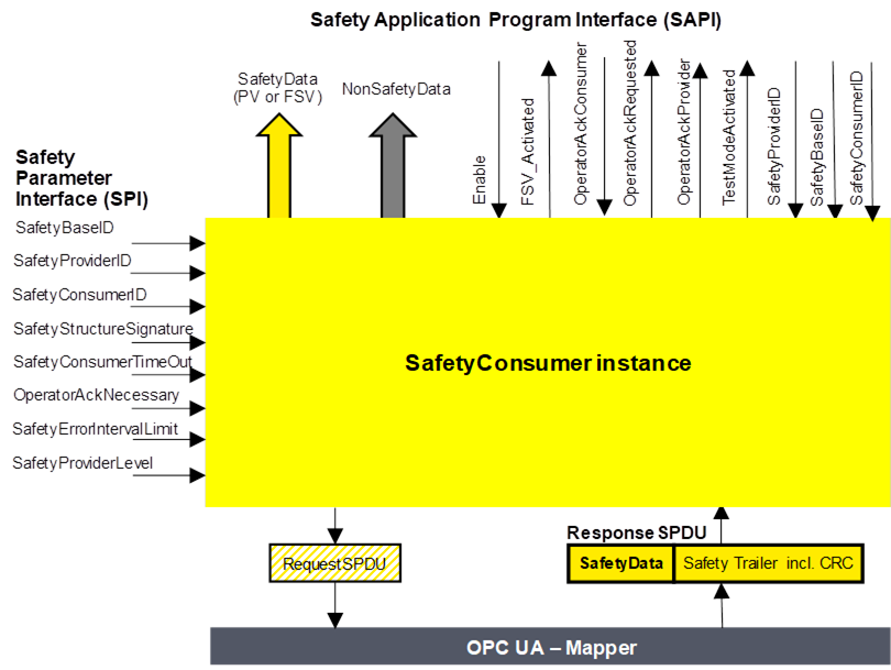
Figure 12 – SafetyConsumer interfaces
The SAPI of the SafetyConsumer represents the Safety communication layer services of the SafetyConsumer. Table 16 lists all inputs and outputs of the SAPI of the SafetyConsumer. [RQ7.4] Each SafetyConsumer shall implement the SAPI as shown in Table 16, however, the details are vendor specific.
Table 16 – SAPI of the SafetyConsumer
|
SAPI Term |
Type |
Definition |
|
Structure |
This output either delivers the process values received from the SafetyProvider in the SPDU field SafetyData, or FSV. |
|
|
Structure |
Used to consistently transmit non-safety data values (e.g. diagnostic information) together with safe data, see Clause 8.1.1.10 |
|
|
Boolean |
By changing this input to "0" the SafetyConsumer will change each and every variable of the SafetyData to "0" and stop sending requests to the SafetyProvider. When changing Enable to "1" the SafetyConsumer will restart safe communication. The variable can be used to delay the start of the OPC UA Safety communication, after power on until "OPC UA connection ready" is set. The delay time is not monitored while enable is set to “0”. |
|
|
Boolean |
This output indicates via "1", that on the output SafetyData FSV (all binary "0") are provided. NOTE: If an application needs different FSV than “all binary 0”, it is expected to use appropriate constants and ignore the output of SafetyData whenever FSV_Activated is set.
NOTE: If the ResponseSPDU is checked with error: ActivateFSV is set. |
|
|
OperatorAckConsumer
|
Boolean |
For motivation, see Clause 7.4.2. After an indication of OperatorAckRequested this input can be used to signal an operator acknowledgment. By changing this input from “0” to "1" (rising edge) the SafetyConsumer is instructed to switch SafetyData from FSV to PV. OperatorAckConsumer is processed only if this rising edge arrives after OperatorAckRequested was set to “1”, see Figure 18. If a rising edge of OperatorAckConsumer arrives before OperatorAckRequested becomes 1, this rising edge is ignored.
|
|
OperatorAckRequested |
Boolean |
This output indicates the request for operator acknowledgment. The bit is set to “1” by the SafetyConsumer, when three conditions are met:
The bit is reset to “0” when a rising edge at OperatorAckConsumer is detected. |
|
Boolean |
This output indicates that an operator acknowledgment has taken place on the SafetyProvider. If operator acknowledgment at the SafetyProvider should be allowed, this output is connected to OperatorAckConsumer, see Annex B.2.4 and B.2.5. NOTE: If the ResponseSPDU is checked with error, this output remains last value. |
|
|
Boolean |
The safety application program is expected to evaluate this output for determining whether the communication partner is in test mode or not. A value of “1” indicates that the communication partner (source of data) is in test mode, e.g. during commissioning. Data coming from a device in test mode may be used for testing but is not intended to be used to control safety-critical processes. A value of “0” represents the “normal” safety-related mode. Motivation: Test mode enables the programmer and commissioner to validate the safety application using test data.NOTE: If the ResponseSPDU is checked with error: TestModeActivated is reset. |
|
|
UInt32 |
By changing this input to a non-zero value, the SafetyConsumer uses this variable instead of the SPI-Parameter SafetyProviderID. This input is only read in the first cycle, or when a rising edge occurs at the input Enable. See also Table 17. If it is changed to “0”, the parameter SafetyProviderID will become activated. |
|
|
GUID |
By changing this input to a non-zero-value the SafetyConsumer uses this variable instead of the SPI-Parameter SafetyBaseID. This input is only read in the first cycle, or when a rising edge occurs at the input Enable. See also Table 17. If it is changed to “0”, the SPI-parameter SafetyBaseID will become activated. |
|
|
UInt32 |
By changing this input to a non-zero-value the SafetyConsumer uses this variable instead of the SPI-Parameter SafetyConsumerID. This input is only read in the first cycle, or when a rising edge occurs at the input Enable. See also Table 17. If it is changed to “0”, the SPI-parameter SafetyConsumerID will become activated. |
The safety argumentation assumes that random errors in the underlying OPC UA stack including its communication links are not too frequent, i.e. that its failure rate is lower than a given threshold, depending on the desired SIL.
Whenever the SafetyConsumer detects a faulty telegram, it checks whether the assumption is still valid, and switches to fail-safe substitute values otherwise. Returning to process values then requires an operator acknowledgment.
Operator Acknowledge is expected to be initiated by a human operator who is responsible to check the installation, see “Table 32, row Operator Acknowledge”. For this reason, the OperatorAckConsumer is delivered to the safety application program to deal with.
Timeout errors do only require an operator acknowledgment if operator acknowledgment is required by the safety function itself. In this case, SafetyOperatorAckNecessary is set to indicate that operator acknowledgments required.
[RQ7.5] Each SafetyConsumer shall implement the parameters shown in Table 17 which can be set via the SPI. The mechanisms for setting these parameters are vendor specific. The SPI of the SafetyConsumer represents the parameters of the Safety communication layer management of the SafetyConsumer.
Table 17 – SPI of the SafetyConsumer
|
Identifier |
Type |
Valid range |
Initial Value (before parametrization) |
Note |
|
SafetyBaseID |
GUID |
See Clause 11.1.1 |
0x0 |
The default SafetyBaseID of the SafetyProvider this SafetyConsumer uses to make a connection, see Clause 3.2.25. For dynamic systems, the safety application program can overwrite this ID by providing a non-zero value at the input SafetyBaseID of the SafetyConsumer’ s SAPI. |
|
SafetyProviderID |
UInt32 |
0x1 - 0xFFFFFFFF |
0x0 |
The SafetyProviderID of the SafetyProvider this SafetyConsumer normally connects to, see Figure 10 and Clause 3.2.26. For dynamic systems, the safety application program can overwrite this ID by providing a non-zero value at the input SafetyProviderID of the safety Consumer’s SAPI.
|
|
SafetyConsumerID |
UInt32 |
0x1 - 0xFFFFFFFF |
0x0 |
ID of the SafetyConsumer, see Clause 11.1.2. |
|
SafetyStructureSignature |
UInt32 |
0x1 – 0xFFFFFFFF |
0x0 |
Signature over the SafetyData structure, see Clause 8.1.3.4 |
|
SafetyConsumerTimeOut |
UInt32 |
0x1 – 0xFFFFFFFF |
0x1 |
Watchdog-time in microseconds (µs). Whenever the SafetyConsumer sends a request to a SafetyProvider, its watchdog timer is set to this value. The expiration of this timer prior to receiving an error-free reply by the SafetyProvider indicates an unacceptable delay. See Clause 10.2 |
|
SafetyOperatorAckNecessary |
Boolean |
0x0 / 0x1Default 1 |
0x1 |
This parameter controls whether an operator acknowledgment (OA) is necessary in case of errors of type “unacceptable delay” or “loss”, or when the SafetyProvider has activated FSV (ActivateFSV). 1: FSV are provided at the output SafetyData of the SAPI until OA. 0: PV are provided at SafetyData of the SAPI as soon as the communication is free of errors. In case of ActivateFSV the values change from FSV to PV as soon as ActivateFSV returns to “0”.
Note: This parameter does not have an influence on the behavior of the SafetyConsumer following the detection of other types of communication errors, such as data corruption. For these types of errors, OA is mandatory, see Clause 7.4.2. |
|
SafetyErrorIntervalLimit
|
UInt16 |
6, 60, 600 |
600 |
Value in minutes. The parameter SafetyErrorIntervalLimit determines the minimum distance two consecutive communication errors must have for not triggering a switch to FSV in the SafetyConsumer. It affects the availability and the PFH of this OPC UA Safety link, see Clause 7.4.2 and Clause 11.4. |
|
SafetyProviderLevel
|
Byte |
0x01 - 0x04 |
0x1 |
SafetyConsumer’s expectation on the maximal SIL the SafetyProvider implementation (hardware & software) is capable of. See Clause 7.3.3, Clause 8.1.3.3, and Figure 11. |
NOTE: the engineering system can use the initial value to set a parameter to a safe value.
This parameter determines whether automatic restart is possible for the safety function or not. It is expected to be set to 1 for safety functions where automatic restart is not allowed and restart always requires human interaction.
If automatic restart of the safety function is safe, the parameter can be set to 0.