The two SCL-services “SafetyProvider” and “SafetyConsumer” are specified using state diagrams.
Figure 15 shows the sequence of request and response with SafetyData and the timeouts for OPC UA Safety.
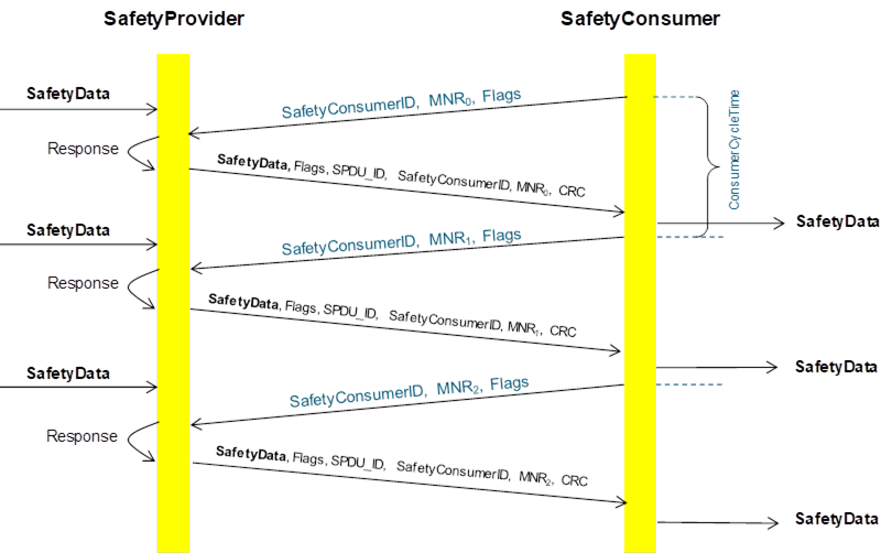
NOTE: Transmission errors are handled within the OPC UA stack (e.g. when using client/server over TCP) and do not have to be corrected or re-transmitted by OPC UA Safety.
Figure 15 – Sequence diagram for OPC UA Safety
The SafetyConsumerTimeout is the watchdog time checked in the SafetyConsumer. The watchdog is restarted whenever a new RequestSPDU is generated (transitions T14 and T26 of the SafetyConsumer). If an appropriate ResponseSPDU is received in time, and the checks for data integrity, authenticity, and timeliness are all valid, the timer will not expire before it is restarted.
Otherwise, the watchdog timer expires, and the SafetyConsumer triggers a safe reaction. To duly check its timer, the SafetyConsumer is executed cyclically, with period ConsumerCycleTime. ConsumerCycleTime is expected to be smaller than SafetyConsumerTimeout.
The ConsumerCycleTime is the maximum time for the cyclic update of the SafetyConsumer. It is the timeframe from one call of the SafetyConsumer to the next call of the SafetyConsumer. The implementation and error reaction of ConsumerCycleTime is not part of OPC UA Safety; it is vendor specific.
[RQ8.10] Figure 16 shows a simplified representation of the state diagram of the SafetyProvider. The exact behavior is described in Table 21, Table 22, and Table 23. The SafetyProvider shall implement that behavior. It is not required to literally follow the entries given in the tables, if the behavior does not change.
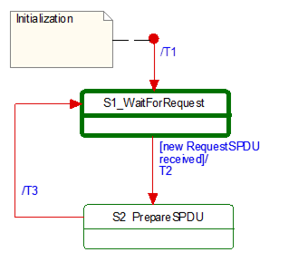
Figure 16 – Simplified representation of the state diagram for the SafetyProvider
|
Graphical representation |
Type |
Description |
|
|
Activity State |
Within these interruptible "activity" states the SafetyProvider waits for new inputs. |
|
|
Action State |
Within these non-interruptible "action" states events like new request is deferred until the next "activity" state is reached, see [1]. |
The transitions are fired in case of an event, for example receiving a SPDU. In case of several possible transitions, so-called guard conditions (refer to […] in UML diagrams) define which transition to fire
The diagram consists of activity and action states. Activity states are surrounded by bold lines, action states are surrounded by thin lines. While activity states may be interruptible by new events, action states are not. External events occurring while the state machine is in an action state, are deferred until the next activity state is reached.
Table 20 – Symbols used for state machines.
Table 21 – SafetyProvider instance internal items
|
INTERNAL ITEMS |
TYPE |
DEFINITION |
|
RequestSPDU_i |
Variable |
Local Memory for RequestSPDU (required to react on changes). |
|
<Get RequestSPDU> |
Macro |
Instruction to take the whole RequestSPDU from the OPC UA Mapper. |
|
<Set ResponseSPDU> |
Macro |
Instruction to transfer the whole ResponseSPDU to the OPC UA Mapper |
|
<build ResponseSPDU> |
Macro |
Take the MNR and the SafetyConsumerID of the received RequestSPDU. Add the SPDU_ID_1, SPDU_ID_2, SPDU_ID_3, Flags, and SafetyData, as well as the calculated CRC. See Clause 8.1.3.1 |
Table 22 – States of SafetyProvider instance
|
STATE NAME |
STATE DESCRIPTION |
|
Initialization |
// Initial state SAPI.SafetyData:= 0SAPI.MonitoringNumber:= 0SAPI.SafetyConsumerID:= 0 RequestSPDU_i:= 0 |
|
S1_WaitForRequest |
// waiting on next RequestSPDU from SafetyConsumer <Get RequestSPDU> |
|
S2_PrepareSPDU |
ResponseSPDU.Flags.ActivateFSV := SAPI.ActivateFSVResponseSPDU.Flags.OperatorAckProvider := SAPI.OperatorAckProvider Response.Flags.TestModeActivated := SAPI.EnableTestMode <build ResponseSPDU> // see Clause 8.1.3.1 |
Table 23 – SafetyProvider driver transitions
|
TRAN-SITION |
SOURCE STATE |
TARGET STATE |
GUARD CONDITION |
ACTIVITY |
|
T1 |
Init |
1 |
- |
|
|
T2
|
1
|
2 |
// RequestSPDU received <Get RequestSPDU> When: [RequestSPDU_i<> RequestSPDU] |
// Process Request RequestSPDU_i:= RequestSPDU SAPI.MonitoringNumber:= RequestSPDU.MonitoringNumber SAPI.SafetyConsumerID := RequestSPDU.SafetyConsumerID |
|
T3 |
2 |
1 |
// SPDU is prepared - |
<Set ResponseSPDU> |
[RQ8.11] Figure 17 shows a simplified representation of the state diagram of the SafetyConsumer. The exact behavior is described in Table 24, Table 25, and Table 26. The SafetyConsumer shall implement that behavior. It is not required to literally follow the entries given in the tables, if the behavior does not change.
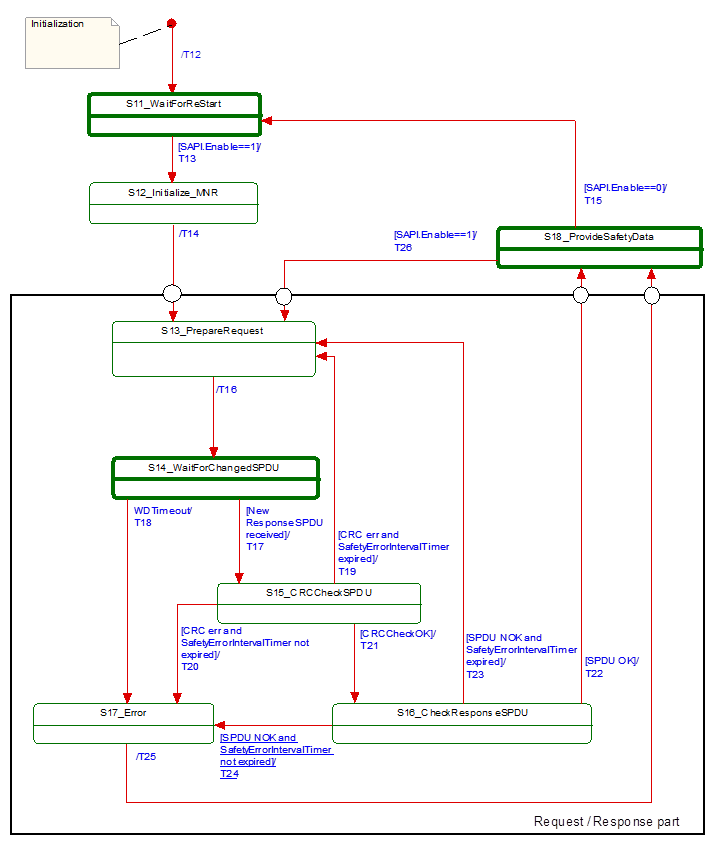
Figure 17 – Principle state diagram for SafetyConsumer
Table 24 – SafetyConsumer driver internal items
|
INTERNAL ITEMS |
TYPE |
DEFINITION |
|
Constants |
|
|
|
MNR_min := 0x100 |
UInt32 |
// 0x100 is the start value for MNR, also used after wrap-around. // The values 0…0xFF are reserved for future use. |
|
Variables |
|
|
|
FaultReqOA_i |
Boolean |
Local memory for errors which request operator acknowledgment. |
|
MNR_i |
UInt32 |
Local Monitoring Number (MNR). |
|
prevMNR_i |
UInt32 |
Local memory for previous MNR |
|
SafetyProviderID_i |
UInt32 |
Local memory for SafetyProviderID in use. |
|
CRCCheck_i |
Boolean |
Local variable used to store the result of the CRC-check. |
|
SPDUCheck_i |
Boolean |
Local variable used to store the result of the additional SPDU-checks. |
|
SPDU_ID_1_i |
UInt32 |
Local variable to store the expected SPDU_ID_1 |
|
SPDU_ID_2_i |
UInt32 |
Local variable to store the expected SPDU_ID_2 |
|
SPDU_ID_3_i |
UInt32 |
Local variable to store the expected SPDU_ID_3 |
|
Timers |
|
|
|
ConsumerTimer |
Timer |
This timer is used to check whether the next valid ResponseSPDU has arrived on time. It is initialized using the parameter SPI.SafetyConsumerTimeOut. |
|
ErrorIntervalTimer |
Timer |
This timer is initialized using the parameter SPI.SafetyErrorIntervalLimit. See Table 17, Clause 7.4.2, and Clause 11.4 for more information.
|
|
Macros <...><...> |
|
|
|
<risingEdge x> |
Macro |
// detection of a rising edge: If x==true && tmp==false Then result:= trueElse result := falseEndif tmp := x |
|
<Get ResponseSPDU> |
Macro |
Instruction to take the whole ResponseSPDU from the OPC UA Mapper. |
|
<Use FSV> |
Macro |
SafetyData is set to binary 0 SAPI.FSV_Activated := 1 RequestSPDU.Flags.FSV_Activated := 1
NOTE: If a safety application prefers different fail-safe values than binary 0, this can be implemented in the safety application by querying SAPI.FSV_Activated. |
|
<Use SafetyData> |
Macro |
SAPI.SafetyData is set to ResponseSPDU. SafetyData SAPI.FSV_Activated := 0 RequestSPDU.Flags.FSV_Activated := 0 RequestSPDU.Flags.CommunicationError:=0 |
|
<Set RequestSPDU> |
Macro |
Instruction to transfer the whole RequestSPDU to the OPC UA Mapper |
|
<(Re)Start ConsumerTimer> |
Macro |
Restarts the consumer timer. |
|
<(Re)Start ErrorIntervalTimer> |
Macro |
Restarts the error interval timer. |
|
<ConsumerTimer expired?> |
Macro |
Yields “true” if the timer is running longer than SPI.SafetyConsumerTimeOut since last restart, “false” otherwise. |
|
<ErrorIntervalTimer expired?> |
Macro |
Yields “true” if the timer is running longer than SPI.SafetyErrorIntervalLimit since last restart, “false” otherwise. |
|
<Build RequestSPDU> |
Macro |
RequestSPDU.SafetyConsumerID := SPI.SafetyConsumerID RequestSPDU.MonitoringNumber := MNR_i
|
|
<Calc SPDU_ID_i> |
Macro |
uint128 BaseID uint32 ProviderID const uint32 SafetyProviderLevel_ID := … // see Clause 8.1.3.3 If(SAPI.SafetyBaseID == 0) thenBaseID := SPI.SafetyBaseIDElse BaseID := SAPI.SafetyBaseID Endif If(SAPI.SafetyProviderID == 0) thenProviderID := SPI.SafetyProviderIDElse ProviderID := SAPI.SafetyProviderID Endif SPDU_ID_1_i := BaseID (bytes 0…3) XOR SafetyProviderLevel_ID SPDU_ID_2_i := BaseID (bytes 4…7) XOR SPI.SafetyStructureSignature SPDU_ID_3_i := BaseID (bytes 8…11) XOR BaseID (bytes 12…15) XOR ProviderID // see Clause 8.1.3.2 for clarification |
|
<Set Diag(ID, Boolean permanent)> |
Macro |
// ID is the identifier for the type of diagnostic output, see Table 29// permanent is used to indicate a permanent error. // Only one diagnostic message is created for multiple permanent // errors in sequence If(RequestSPDU.Flags.CommunicationError == 0) Then <do vendor-specific function for diagnostic output using ID>Else //do nothingEndif
RequestSPDU.Flags.CommunicationError:= permanent // Note: See for possible values for “ID” and their codes. |
|
External Event |
|
|
|
Restart Cycle |
Event |
The external call of SafetyConsumer can be interpreted as event “Restart Cycle” |
Note: A macro is a shorthand representation for operations described in the according definition.
Table 25 – SafetyConsumer driver states
|
STATE NAME |
STATE DESCRIPTION |
|
Initialization |
// Initial state of the SafetyConsumer driver instance. <Use FSV> SAPI.OperatorAckRequested := 0RequestSPDU.Flags.OperatorAckRequested :=0SAPI.OperatorAckProvider := 0FaultReqOA_i :=0SAPI.TestModeActivated := 0RequestSPDU.Flags.CommunicationError:= 0 |
|
S11_Wait for (Re)Start |
// Safety Layer is waiting (Re)Start |
|
S12_initialize MNR |
// Use previous MNR if known// or random MNR within the allowed range (e.g. after cold start), see Clause 11.2. MNR_i := (previous MNR_i if known) or (random MNR) MNR_i := max(MNR_i, MNR_min) |
|
S13_PrepareRequest |
// Build RequestSPDU and send (done in T16) |
|
S14_WaitForChangedSPDU |
// Safety Layer is waiting on next ResponseSPDU from SafetyProvider |
|
S15_CRCCheckSPDU |
// Check CRC
uint32 CRC_calcCRCCheck_i := (CRC_calc == ResponseSPDU.CRC) // see Clause 8.1.3.5 on how to calculate CRC_calc |
|
S16_CheckResponseSPDU |
// Check SafetyConsumerID and SPDU_ID and MNR (see T22, T23, T24)
SPDUCheck_i := ResponseSPDU.SPDU_ID_1== SPDU_ID_1_i && ResponseSPDU.SPDU_ID_2== SPDU_ID_2_i && ResponseSPDU.SPDU_ID_3== SPDU_ID_3_i && ResponseSPDU.SafetyConsumerID== SPI.SafetyConsumerID && ResponseSPDU.MNR==MNR_i |
|
S17_Error |
SAPI.TestModeActivated := 0 |
|
S18_ProvideSafetyData |
// Provide SafetyData to the application program |
Table 26 – SafetyConsumer driver transitions
|
TRANSITION |
SOURCE STATE |
TARGET STATE |
GUARD CONDITION |
ACTIVITY |
|
T12 |
Init |
S11 |
- |
|
|
T13 |
S11 |
S12
|
//Start [SAPI.Enable==1] |
<(Re)Start ErrorIntervalTimer><calc SPDU_ID>// see Clause 8.1.3.2 for clarification |
|
T14 |
S12 |
S13 |
// MNR initialized |
<(Re)Start ConsumerTimer> |
|
T15 |
S18 |
S11 |
// Termination [SAPI.Enable==0] |
<Use FSV> |
|
T16 |
S13 |
S14 |
// Build Request SPDU and send
|
prevMNR_i := MNR_i, If MNR_i== 0xFFFFFFFFFThen MNR_i := MNR_min,Else MNR_i := MNR_i + 1Endif <Build RequestSPDU> <Set RequestSPDU> |
|
T17 |
S14 |
S15 |
// New ResponseSPDU received <Get ResponseSPDU> [ResponseSPDU.MNR<>prevMNR_i] |
- |
|
T18 |
S14 |
S17 |
// WDTimeout [<ConsumerTimer expired?>] |
<Set Diag(CommErrTO,1)><use FSV> If SPI.SafetyOperatorAckNecessary == 1Then FaultReqOA_i := 1Else // do nothingEndif |
|
T19 |
S15 |
S13 |
// When CRC err and SafetyErrorIntervalTimer expired[(crcCheck_i == 0 ) && <ErrorIntervalTimer expired?>] |
<(Re)Start ErrorIntervalTimer><Set Diag(CRCerrIgn,0)> |
|
T20 |
S15 |
S17 |
// When CRC err and SafetyErrorIntervalTimer not expired [(crcCheck_i == 0 ) && not <ErrorIntervalTimer expired?>] |
<(Re)Start ErrorIntervalTimer><Set Diag(CRCerrOA,1)><use FSV> FaultReqOA_i:= 1
|
|
T21 |
S15 |
S16 |
// When CRCCheckOK [crcCheck_i == 1 ] |
- |
|
T22 |
S16 |
S18 |
// SPDU OK [SPDUCheck_i==1] |
// For clarification, refer to Figure 18
// indicate OA from provider SAPI.OperatorAckProvider := ResponseSPDU.Flags.OperatorAckProvider
// OA requested due to edge at ActivateFSV? If (<risingEdge ResponseSPDU.Flags.ActivateFSV>&& SPI.SafetyOperatorAckNecessary == 1)Then FaultReqOA_i:=1;<Set Diag(FSV_Requested,1)> Else // do nothing Endif // Set Flags if OA requested: If FaultReqOA_i==1 Then SAPI.OperatorAckRequested:= 1, RequestSPDU.Flags.OperatorAckRequested:=1, FaultReqOA_i:= 0Else //do nothingEndif // Reset flags after OA: If (<risingEdge SAPI.OperatorAckConsumer >) Then SAPI.OperatorAckRequested:=0, RequestSPDU.Flags.OperatorAckRequested:=0Else // do nothingEndif If SAPI.OperatorAckRequested==1 || ResponseSPDU.ActivateFSV==1Then <use FSV> Else <use SafetyData>Endif
// Notify safety application that SafetyProvider is in test mode: SAPI.TestModeActivated:= ResponseSPDU.Flags.TestModeActivated |
|
T23 |
S16 |
S13 |
// SPDU NOK and SafetyErrorIntervalTimer expired[SPDUCheck_i == 0 && <ErrorIntervalTimer expired?>] |
<(Re)Start ErrorIntervalTimer>,// Send diagnostic message according the// detected error: If ResponseSPDU.SafetyConsumerID<> SPI.SafetyConsumerIDThen <Set Diag(CoIDerrIgn,0)>ElseIf ResponseSPDU.MNR<>MNR_iThen <Set Diag(MNRerrIgn,0)> Else //do nothing EndIf If ResponseSPDU.SPDU_ID_1<> SPDU_ID_1_i || ResponseSPDU.SPDU_ID_2<> SPDU_ID_2_i || ResponseSPDU.SPDU_ID_3<> SPDU_ID_3_iThen <Set Diag(SD_IDerrIgn,0)> Else // do nothing Endif Endif
|
|
T24 |
S16 |
S17 |
// SPDU NOK and SafetyErrorIntervalTimer not expired [SPDUCheck_i == 0 && not <ErrorIntervalTimer expired?>] |
<(Re)Start ErrorIntervalTimer>// Send diagnostic message according the // detected error: If ResponseSPDU.SafetyConsumerID<> SPI.SafetyConsumerIDThen <Set Diag(CoIDerrIgn,1)>Else If ResponseSPDU.MNR<>MNR_iThen <Set Diag(MNRerrIgn,1)> Else //do nothing Endif If ResponseSPDU.SPDU_ID_1<> SPDU_ID_1_i || ResponseSPDU.SPDU_ID_2<> SPDU_ID_2_i || ResponseSPDU.SPDU_ID_3<> SPDU_ID_3_iThen <Set Diag(SD_IDerrIgn,1)> <use FSV> Else //do nothing Endif Endif FaultReqOA_i:= 1 |
|
T25 |
S17 |
S18 |
// SPDU NOK - |
|
|
T26 |
S18 |
S13 |
// Restart Cycle [SAPI.Enable==1] |
<(Re)Start ConsumerTimer> |
Figure 18 shows the sequence after a second ResponseSPDU error was detected before the timer SafetyErrorIntervalTimer stops.
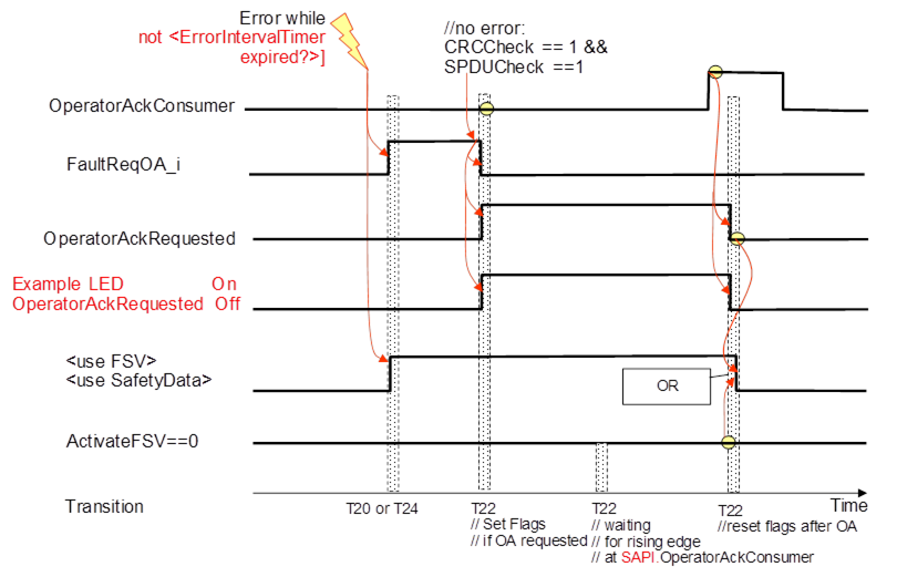
Figure 18 – Sequence diagram for OA
After the error is gone the sequence follows the logic of T22 in Table 26.