Table 128 defines the namespace metadata for this document. The Object is used to provide version information for the namespace and an indication about static Nodes. Static Nodes are identical for all Attributes in all Servers, including the Value Attribute. See OPC 10000-5 for more details.
The information is provided as Object of type NamespaceMetadataType. This Object is a component of the Namespaces Object that is part of the Server Object. The NamespaceMetadataType ObjectType and its Properties are defined in OPC 10000-5.
The version information is also provided as part of the ModelTableEntry in the UANodeSet XML file. The UANodeSet XML schema is defined in Table 128.
Table 128 – NamespaceMetadata Object for this Document
|
Attribute |
Value |
||
|
BrowseName |
|||
|
Property |
DataType |
Value |
|
|
NamespaceUri |
String |
||
|
NamespaceVersion |
String |
1.01 |
|
|
NamespacePublicationDate |
DateTime |
2025-08-25 |
|
|
IsNamespaceSubset |
Boolean |
False |
|
|
StaticNodeIdTypes |
IdType [] |
0 |
|
|
StaticNumericNodeIdRange |
NumericRange [] |
|
|
|
StaticStringNodeIdPattern |
String |
|
|
Note: The IsNamespaceSubset Property is set to False as the UANodeSet XML file contains the complete Namespace. Servers only exposing a subset of the Namespace need to change the value to True.
Namespaces are used by OPC UA to create unique identifiers across different naming authorities. The Attributes NodeId and BrowseName are identifiers. A Node in the UA AddressSpace is unambiguously identified using a NodeId. Unlike NodeIds, the BrowseName cannot be used to unambiguously identify a Node. Different Nodes may have the same BrowseName. They are used to build a browse path between two Nodes or to define a standard Property.
Servers may often choose to use the same namespace for the NodeId and the BrowseName. However, if they want to provide a standard Property, its BrowseName shall have the namespace of the standards body although the namespace of the NodeId reflects something else, for example the EngineeringUnits Property. All NodeIds of Nodes not defined in this document shall not use the standard namespaces.
Table 129 provides a list of mandatory and optional namespaces used in an OPC UA for Robotics Server.
Table 129 – Namespaces used in a OPC Robotics Server.
|
NamespaceURI |
Description |
Use |
|
Namespace for NodeIds and BrowseNames defined in the OPC UA specification. This namespace shall have namespace index 0. |
Mandatory |
|
|
Local Server URI |
Namespace for nodes defined in the local server. This namespace shall have namespace index 1. |
Mandatory |
|
Namespace for NodeIds and BrowseNames defined in OPC 10000-100. The namespace index is Server specific. |
Mandatory |
|
|
Namespace for NodeIds and BrowseNames defined in OPC UA for Machinery. The namespace index is Server specific. |
Optional |
|
|
Namespace for NodeIds and BrowseNames defined in this document. The namespace index is Server specific. |
Mandatory |
|
|
Vendor specific types |
A Server may provide vendor-specific types like types derived from ObjectTypes defined in this document in a vendor-specific namespace. |
Optional |
|
Vendor specific instances |
A Server provides vendor-specific instances of the standard types or vendor-specific instances of vendor-specific types in a vendor-specific namespace. It is recommended to separate vendor specific types and vendor specific instances into two or more namespaces. |
Mandatory |
Table 130 provides a list of namespaces and their indices used for BrowseNames in this document. The default namespace of this document is not listed since all BrowseNames without prefix use this default namespace.
Table 130 – Namespaces used in this document.
|
NamespaceURI |
Namespace Index |
Example |
|
0 |
0:EngineeringUnits |
|
|
2 |
2:DeviceRevision |
|
|
3 |
3:MachineIdentificationType |
(normative) OPC UA for Robotics Namespace and mappings
The Robotics Information Model is identified by the following URI:
http://opcfoundation.org/UA/Robotics/
Documentation for the NamespaceUri can be found here.
The NodeSet associated with this version of specification can be found here:
https://reference.opcfoundation.org/nodesets/?u=http://opcfoundation.org/UA/Robotics/&v=1.01.3&i=1
The NodeSet associated with the latest version of the specification can be found here:
https://reference.opcfoundation.org/nodesets/?u=http://opcfoundation.org/UA/Robotics/&i=1
Supplementary files for the Robotics Information Model can be found here:
https://reference.opcfoundation.org/nodesets/?u=http://opcfoundation.org/UA/Robotics/&v=1.01.3&i=2
The files associated with the latest version of the specification can be found here:
https://reference.opcfoundation.org/nodesets/?u=http://opcfoundation.org/UA/Robotics/&i=2
The capability identifier for this document shall be:
Robotics
___________
This chapter describes examples for motion device systems, motion devices, axes, and power trains.
In addition, this chapter contains examples of how to use the references contained in this specification.
Typically, a motion device system consists of at least one manipulator and one control unit. Manipulators shown in Figure B.1, Figure B.2, Figure B.3, Figure B.4, Figure B.5, Figure B.6 and Figure B.7 normally have only one control unit.
Figure B.8 shows an example with four motion devices which can be controlled by one control unit.
The motion device system illustrated in Figure B.9 consists of three motion devices and may have one or more control units regarding the motion devices. When a safety PLC is integrated in this motion device system, it can be described as an own instance of a ControllerType. This Instance would have no Reference to an instance of a motion device because the safety PLC doesn´t control a manipulator. It could however have a Reference to the instantiated SafetyStates.
The motion devices shown in Figure B.8 are typically controlled by one controller unit. Each motion device IsControlledBy the same controller.
The system illustrated in Figure B.9 may have two control units. For example, one controller Controls both articulated robots and the mobile platform IsControlledBy the other controller.
A motion device can be any manipulator e.g. a robot, a linear unit, or a turn table. For each motion device which has an own type plate an instance of a MotionDeviceType shall be created.
The kind of motion device shall be described with the Property MotionDeviceCategory of the ParameterSet of the MotionDeviceType by the MotionDeviceCategoryEnumeration, which is based on definitions of ISO 8373:2012.
The Figures Figure B.1 and Figure B.2 show examples of cartesian manipulators.
Figure B.2 shows a portal manipulator, a variant of a cartesian manipulator. Axis 1 in this example is driven with master-slave and a robot-hand is mounted at the flange of the cartesian manipulator.
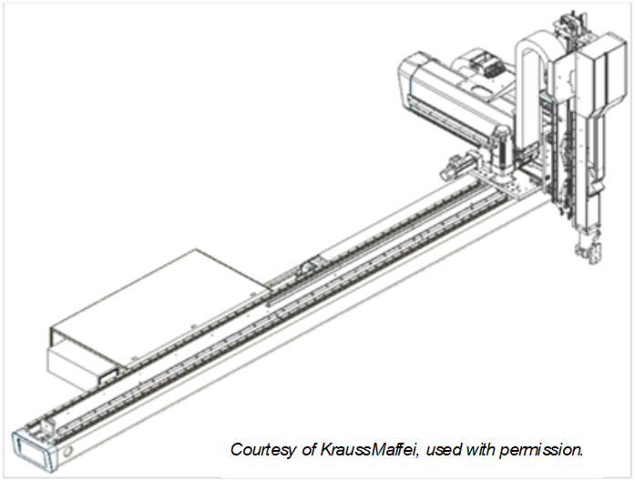
Figure B.1 – Cartesian manipulator
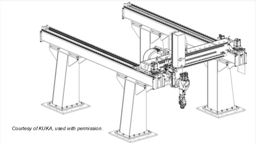
Figure B.2 – Portal manipulator
Figure B.3 shows an example of a parallel manipulator. So called delta robots, as shown in Figure B.4, are also parallel manipulators.
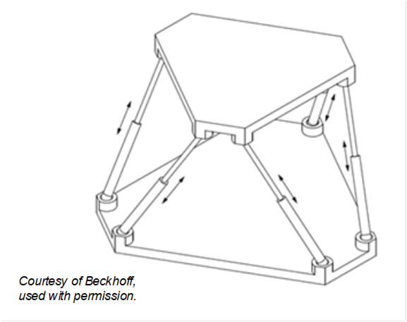
Figure B.3 – Stewart platform or Hexapod
Figure B.4 shows an abstract example of a delta robot.
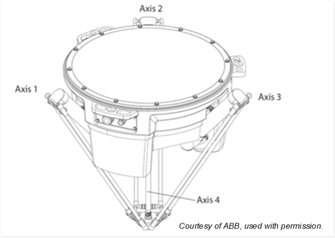
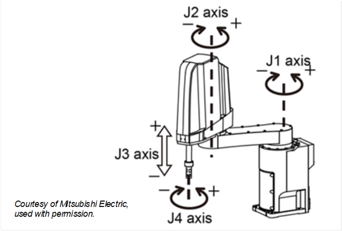
Figure B.5 shows an abstract example of a SCARA robot.
A typical example of an articulated robot is shown in Figure B.6.
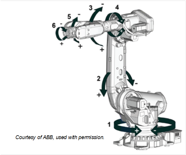
Figure B.6 – Articulated robot
Another example of an articulated robot is a so-called humanoid robot as Figure B.7 schematically shows.
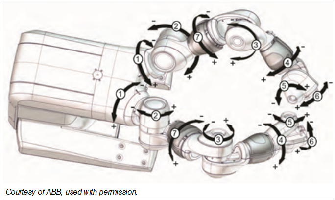
Figure B.7 – Schematic of a humanoid robot
Figure B.8 shows four motion devices integrated in one motion device system: an articulated robot on a linear unit with two turntables.
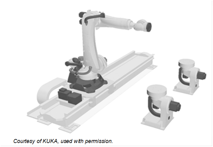
Figure B.8 – Motion device system 1
Figure B.9 shows three motion devices in one motion device system: two articulated robots on a mobile platform.
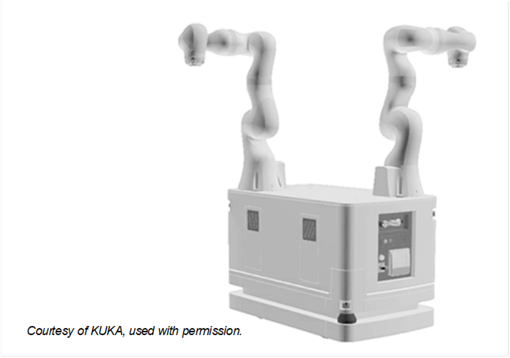
Figure B.9 – Motion device system 2
An axis of a motion device is the mechanical joint of a manipulator that performs a linear or a rotational movement.
Power trains, consisting of gears, motors, and drives, are responsible for the movement of axes. Drives can be integrated in the manipulator or inside a controller cabinet. References describe the relationships between the components of the power train.
Figure B.10 shows two possibilities for a realization of a linear two-dimensional motion device. While in the left figure there is a 1:1 relation between power train and mechanical axis in the right figure power train 1 and power train 2 have effect on the movement of axis 1 and on axis 2. An additional load is located on the mechanical axis 2 but has effect on both power trains.
References describe the relationships between the movement of axes and the power trains that initiate the movement.
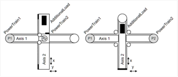
Figure B.10 – Axis and power train coupling
If there is the need to show information about virtual axes, which are not actively run by a power train, then these axes shall be provided, but they don´t have References to a power train. An example for a virtual axis is, when a robot control calculates the movement of an external axis in accordance with the robot movement, e.g. for a servo welding gun mounted at the robot flange, but doesn´t control actively the movement of this axis with an internal power train.
Another example for a virtual axis can be found in a delta robot. When the fourth axis is driven through a telescope shaft and cardan joints, then the length of the telescope shaft is depending on the positions of axes 1, 2 and 3. This length can be seen as a virtual axis, as it has constraints similar to a real axis, e.g. position limits. But it is not possible to actively move this axis.
Figure B.1 and Figure B.2 show different versions of Cartesian robots. Figure B.1 shows a three-axis robot which has one dedicated power train for each axis: A power train Moves exactly one axis and so an axis only Requires one dedicated power train. One motor of a power train IsDrivenBy a drive and IsConnectedTo a gear.
Figure B.2 shows a three-axis robot with a master-slave driven axis 1. The first and second power train Moves axis 1. The first power train HasSlave the second power train. Axis 1 Requires the first and the second power train. For axis 2 and 3 one power train Moves exactly one axis and so an axis only Requires one dedicated power train.
This chapter describes different examples for the usage of DriveType or a SubType of ComponentType defined in OPC 10000-100 inclusive the references described in this specification.
All views show only the instances and references necessary to better illustrate the examples described.
This appendix provides informal examples on how the building blocks defined in OPC UA for Machinery
Part 1: Basic Building Blocks can be used merged with the Robotics Information Model.
Apart from the Machine and Component Identification building blocks, the usage of which are shown in C.2 and C.3 respectively, this companion specification recommends the use of the Operation Counters building block defined in OPC UA for Machinery. The entities in the Motion Device System address place that can make good use of the Operation Counters has been left to the judgement and discretion of the implementer.
In Figure C.21 an example is given, showing the identification and Nameplate and Finding all Machines in Server use cases. The server provides information about a Robotics system.
As this Robotics specification Part 1 already defines some Properties for identification directly, those are only referenced from the Identification functional group.
Note that a Robotics system typically contains several machine parts with own nameplates. E.g. the Declaration of Incorporation of Partly Completed Machinery according Machinery Directive 2006/42/EU for robots provides the Model and the SerialNumber for the robot and for the controller.
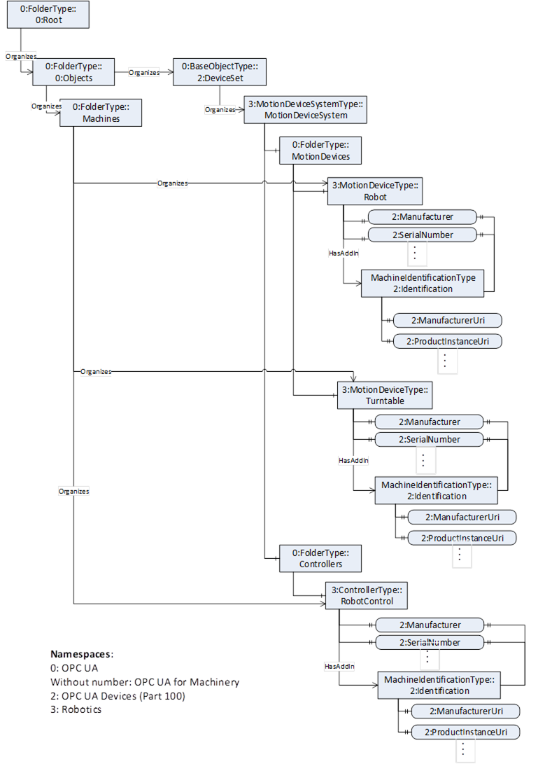
Figure C.21 – Example Finding all Machines and Machine Identification
In Figure C.22, a partially view on an example Robotics system is shown and the components are organized according to the Robotics specification. And in addition, the figure shows according to the OPC UA for Machinery Part 1: Basic Building Blocks the Component Identification and Nameplate and Finding all Components and Machines of a Robotics system.
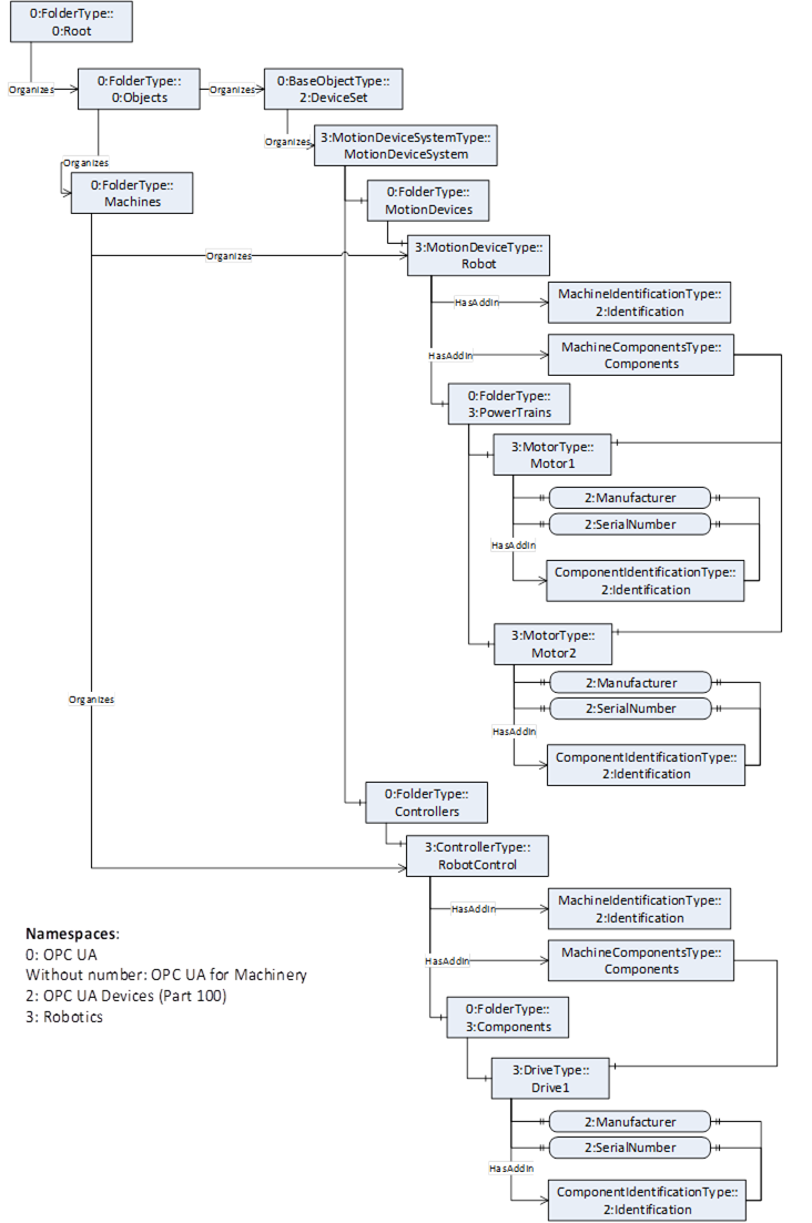
Figure C.22 – Example Finding all Machines and Components and Component Identification