The LoadType is for describing loads mounted on the motion device typically by an integrator or a customer and is formally defined in Table 47. Instances of this ObjectType definition are used to describe the load mounted on one of several mounting points. A very common mounting point is the flange of a motion device. Typically a motion device has additional mounting points on some of the axis. The provided values can either be determined by the robot controller or can be set up by an operator.
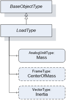
Table 47 – LoadType Definition
|
Attribute |
Value |
||||
|
BrowseName |
LoadType |
||||
|
IsAbstract |
False |
||||
|
References |
Node Class |
BrowseName |
DataType |
TypeDefinition |
Modelling Rule |
|
Subtype of the BaseObjectType defined in OPC Unified Architecture |
|||||
|
HasComponent |
Variable |
Mass |
Double |
AnalogUnitType |
Mandatory |
|
HasComponent |
Variable |
CenterOfMass |
3DFrame |
3DFrameType |
Optional |
|
HasComponent |
Variable |
Inertia |
3DVector |
3DVectorType |
Optional |
The variable Mass provides the weight of the load mounted on one mounting point.
The EngineeringUnits of the Mass shall be provided.
The variable CenterOfMass provides the position and orientation of the center of the mass related to the mounting point using a 3DFrameType. X, Y, Z define the position of the center of gravity relative to the mounting point coordinate system. A, B, C define the orientation of the principal axes of inertia relative to the mounting point coordinate system. Orientation A, B, C can be "0" for systems which do not need these values.
3DFrameType and 3DFrame are defined in OPC 10001-11 (SpatialTypes).
If the instance of the LoadType describes the flange load of a motion device the mounting point coordinate system is the flange coordinate system. If the instance of the LoadType describes an additional load of an axis the mounting point coordinate system is vendor specific and it is up to the vendor to model this coordinate system.
The variable Inertia uses the 3DVektorType to describe the three values of the principal moments of inertia with respect to the mounting point coordinate system. If inertia values are provided for rotary axis the CenterOfMass shall be completely filled as well. Table 48 describes the possible degrees of modelling from a minimal one e.g. only the weight of the mass to a complete one comprising weight, center of mass, principal axes and inertia.
3DVectorType and 3DVector are defined in OPC 10001-11 (SpatialTypes).
Table 48 – LoadType possible degrees of modelling
|
|
Mass |
CenterOfMass |
Inertia |
X, Y, Z |
A, B, C |
|
|
Mass only |
Used |
- |
- |
- |
|
Mass with center of gravity |
Used |
Used |
0, 0, 0 |
- |
|
Mass with inertia |
Used |
Used |
Used |
Used |