4 Concept
4.1 Overview
When the ANSI/ISA-88.01-1995: standard was applied to applications across a plant, there was a need to align the terminologies, models and key definitions between different process types: continuous, batch, and discrete processes. Discrete processes involve machines found in the packaging, converting, and material handling applications. The operation of these machines is typically defined by the OEM, system integrator, end user, or is industry specific.
OMAC (Organization for Machine Automation and Control) created a task group with members from technology providers, OEMs, system integrators, and end users to generate the PackML guidelines as a method to show how the ANSI/ISA-88.01-1995: concepts could be extended into packaging machinery and other types of machines typically used in assembly lines, filling lines, and other production lines.
The purpose of PackML is to:
Define a standard state-based model for automated machines.
Identify definitions for common terminology.
Explain to practitioners how to use state programming for automated machines.
Provide references to actual implementation examples and templates from automation and control vendors.
Identify a common tag structure for automated machines in order to:
Provide for "connect & pack" functionality
Provide functional interoperability and a consistent look and feel across the plant floor.
Provide consistent tag structure for connection to plant MES and enterprise systems.
If automated machinery is modelled in an ANSI/ISA-88.01-1995: physical hierarchy, the example mapping shown in Figure 1 is possible, from ISA-TR88.00.02-2015. The example in this document will assume that a machine can represent the unit level in the ISA88 hierarchy.
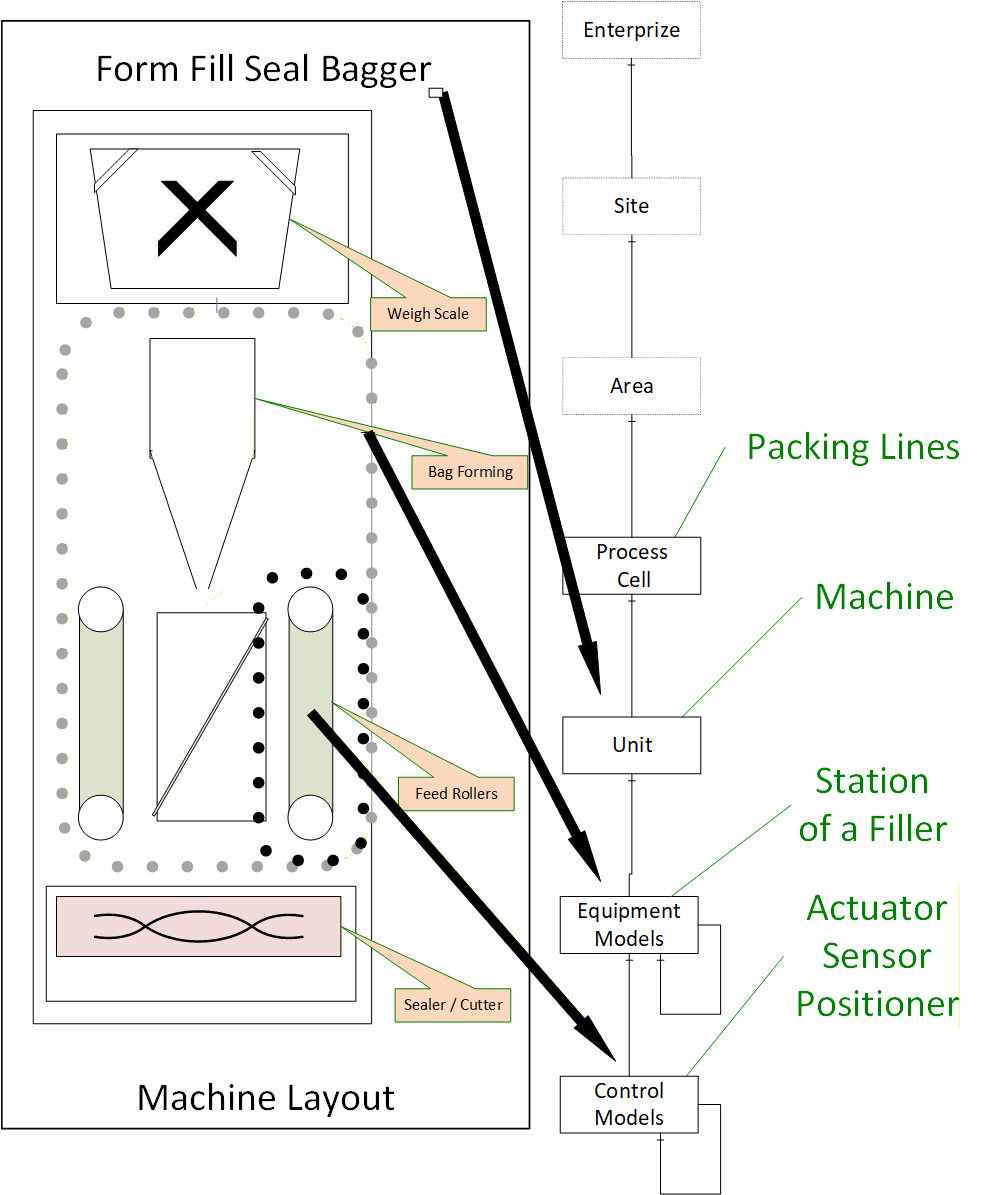
In the figure, the OPC UA interface and the PackML model might exist at the machine level. The communication and interactions below this level are machine specific. Some machines might have multiple Units which communicate using OPC UA / PackML, but they might also only expose the Machine using the OPC UA PackML interface to other Machines in packaging line or to the Packaging line controller.
4.2 PackML Overview
4.2.1 Introduction
For an OPC UA user that may not be familiar with PackML, the following section provides a brief overview of key features that PackML provides along with a little background related to PackML and the concepts behind it.
4.2.2 Why PackML?
The Organization for Machine Automation and Control (OMAC) was formed to help manufacturers work together to find new and innovative ways to be successful in their production operations. OMAC brought together leading manufacturers representing End-User Manufacturers, OEM Machine Builders, System Integrators, Technology Providers, and Non-Profit / Government Agency organizations to address issues that confront global manufacturing today. OMAC aims to collectively derive common solutions for both technical and non-technical issues in the development, implementation, and commercialization of open, modular architecture control technologies.
Manufacturing systems are made of collections of equipment, often from multiple suppliers, usually each with its own specific and custom interface. In order to make this collection of equipment operate together as a complete system, there is an integration effort required, and it is often time consuming and custom for each supplier.
PackML stands for Packaging Machine Language and is an interface standard originally used in batch manufacturing in the packaging industry but which is now used in multiple different types of production and assembly lines. The primary objective of PackML is to bring a common "look and feel" and operational consistency to all machines that make up a production line. PackML provides:
| • | Standard defined machine states and operational flow |
| • | Overall Equipment Effectiveness (OEE) data |
| • | Root Cause Analysis (RCA) data |
| • | Flexible recipe schemes and common SCADA or MES inputs |
PackML has been implemented in multiple formats for different industrial networks, with a proven benefit of reducing the integration time for adding new equipment to existing lines, or installing new lines.
4.2.3 PackML Elements
In order to provide a standard interface PackML defines three elements:
PackML Unit Modes - A standard model that is used to control which state is being used (Producing, Maintenance, Manual, ….).
PackML StateMachine - Standard state machine models that are used to represent the internal operational state of the machine/unit. [note: StateMachine may change for Units and for the Mode of the unit]
PackTags -A standard set of tag names and extension used to control the mode and state, send commands to the machine/unit, and monitor the status of the machine/unit.
These three aspects will be translated to OPC UA models
4.2.4 Standard Modes
A Unit can be in different modes, for example Producing, Maintenance, Manual, Clean, Calibration, etc. A Unit control mode is an ordered subset of states and commands that determines the strategy carried out by the Unit process, as shown in Figure 2. For example, the producing mode is used when the unit is producing, a manual mode may be used when the unit is being manually controlled for troubleshooting.
The states that a unit can be in depends on the mode. In the producing mode there is a state called SUSPENDED, where the equipment is not running due to an external event, but this state is not available in maintenance mode, neither is the COMPLETE state.
PackML includes a standard manner of changing modes as well as displaying the current mode. For additional information please see the ISA-TR88.00.02-2015.
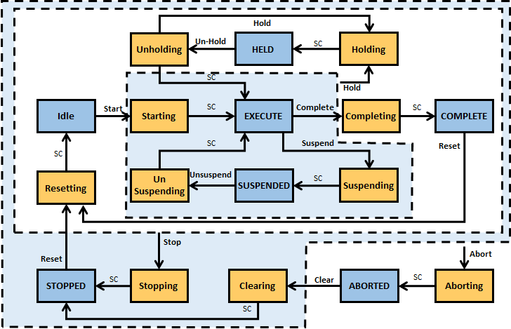
4.2.5 Standard States
PackML Interface State Model is used to visualize and control the state of a unit/machine. The PackML Interface State Model is a state model that represents the Unit/Machine State in a standardized manner. The interface description is based on a state model, a state description and related control commands. For additional information see ISA-TR88.00.02-2015.
4.2.6 Standard Tag Names
At its core, PackML is the definition of standard tag names and standard values for the tags. These are used to control the state model of the unit (command tags), determine the state and status of the equipment (status tags), and administer the equipment (admin tags).
4.2.7 PackML Object Model
4.2.7.1 Overview
The PackML object model is composed of a series of tags. These tags can be one of three general type of tags Command Tags, Status Tags and Administrative Tags.
4.2.7.2 Command Tags
Command tags allow interaction with the state machine and general functionality of the server. Command tags include changing units, changing state machines. For additional detail see ISA-TR88.00.02-2015. In OPC UA command tags are generally mapped to Methods.
4.2.7.3 Status Tags
Status tags provide information about the state of the machine or device. This includes feedback from the commands issued and the general status. For additional detail see ISA-TR88.00.02-2015.
4.2.7.4 Admin Tags
Admin tags provide information about alarming in the machines or device. This include Alarm history and some summary statistics about the machine or device. For additional detail see ISA-TR88.00.02-2015.
4.2.8 Standard Tag Values
4.2.8.1 Overview
Several PackTags have specific values defined.
4.2.8.2 Machine Speed
This describes the set point for the current speed of the unit/machine in primary packages per minute. Keeping speed in a primary package unit of measure (UOM) allows for easier control integration. The primary package UOM is the normalized rate for the machine, normalized to a value chosen on the line.
The following example is for a bottle line running at balance line speed of 1000 packages/minute. The UOM chosen is equivalent to be the actual count of the Filler, or Labeler.
| Machine | Actual Pack Counts | Primary Packages (UOM) |
| Bulk Depalletizer | 41.667 (24 pack => 1000/24 = 41.667) | 1,000 |
| Filler | 1,000 | 1,000 |
| Labeler | 1,000 | 1,000 |
| Packer | 66.667 (15 pack => 1000/15 = 66.667) | 1,000 |
| Bulk Depalletizer | 41.667 (24 pack => 1000/24 = 41.667) | 1,000 |
4.2.8.3 Material Interlock
Indicates materials are ready for processing. It is comprised of a series of bits with 1 equalling ready or not low, 0 equalling not ready, or low. Each bit represents a different user material. The word contains bits that indicate when a critical material or process parameter is ready for use. It can also be used for production, and/or indication of low condition. This information may be sent to the unit machine at any time as the interlock information changes.
The format and meaning of the material interlock bits are determined by the machine/unit supplier, as shown in the example below:
| Machine/Unit | Material Interlock Bit # | Material Description |
| Filler | 0 | 500 ml Bag |
| Filler | 1 | Flacked Cereal |
| Labeler | 0 | Small Box |
| Labeler | 1 | 500 ml Bag |
| Labeler | 2 | Small Box Label |
4.2.8.4 Remote Interface Structure
An array of structure elements used for coordinating upstream or downstream machines in a cell with multiple unit machines.
The array is a length that is equal to the number of machines that will be sending commands. This could be expanded if a machine is capable of receiving material from multiple upstream and/or downstream machines, thereby receiving multiple commands and parameters.
This can be used for machine to machine coordination without supervisory control, or for tightly controlled units under supervisory control. These tags are typically used for consumption within the unit machine procedure. Specifically, if a remote controller was issuing commands, the commands would be read by this tag and used in the unit machine.
4.3 OPC UA Overview
4.3.1 Introduction
For PackML users that may not be familiar with OPC UA the following section provides a brief overview of key features that OPC UA provides.
4.3.2 What is OPC UA?
OPC UA is an open and royalty free set of standards designed as a universal communications protocol. While there are numerous communication solutions available, OPC UA has several advantages:
A state of art security model (see OPC 10000-2).
A fault tolerant communication protocol.
An information modelling framework that allows application developers to represent their data in a way that makes sense to them.
OPC UA has a broad scope which delivers for economies of scale for application developers. This means that a larger number of high quality applications at a reasonable cost are available. When combined with powerful semantic models such as PackML, OPC UA makes it easier for end users to access data via generic commercial application.
The OPC UA model is scalable from small devices to ERP systems. OPC UA devices process information locally and then provide that data in a consistent format to any application requesting data - ERP, MES, PMS, Maintenance Systems, HMI, Smartphone or a standard Browser, for examples. For a more complete overview see OPC 10000-1.
4.3.3 Basics of OPC UA
As an Open Standard, OPC UA is based on standard Internet technologies - TCP/IP, HTTPS, Ethernet, and XML.
As an Extensible Standard, OPC UA provides a set of services (see OPC 10000-4) and a basic information model framework. This framework provides an easy manner for creating and exposing vendor defined information in a standard way. More importantly all OPC UA Clients are expected to be able to discover and use vendor defined information. This means OPC UA users can benefit from the economies of scale that come with generic visualization and historian applications. This specification is an example of an OPC UA Information Model designed to meet the needs of developers and users.
OPC UA Clients can be any consumer of data from another device on the network to browser based thin clients and ERP systems. The full scope of OPC UA applications are shown in Figure 3.
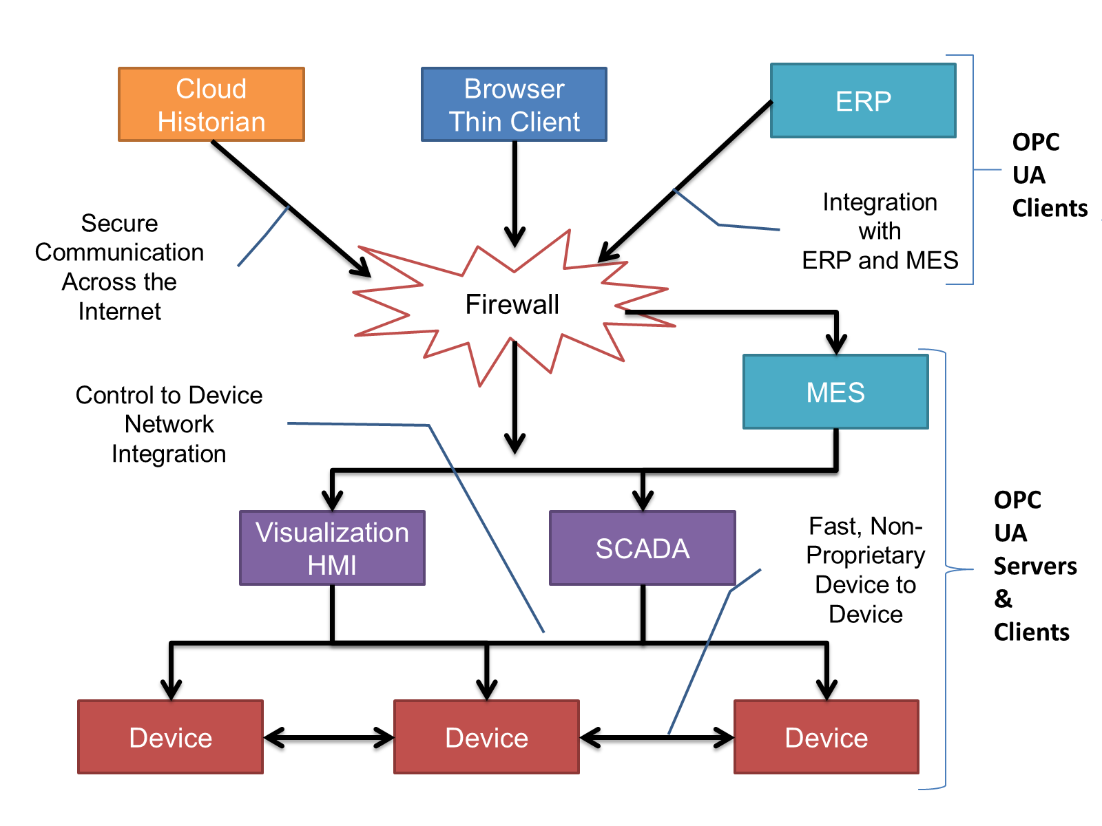
OPC UA provides a robust and reliable communication infrastructure having mechanisms for handling lost messages, failover, heartbeat, etc. With its binary encoded data, it offers a high-performing data exchange solution. Security is built into OPC UA as security requirements become more and more important especially since environments are connected to the office network or the internet and attackers are starting to focus on automation systems
4.3.4 Information Modelling in OPC UA
4.3.4.1 Concepts
OPC UA provides a framework that can be used to represent complex information as Objects in an address space which can be accessed with standard web services. These Objects consist of Nodes connected by References. Different classes of Nodes convey different semantics. For example, a Variable Node represents a value that can be read or written. The Variable Node has an associated DataType that can define the actual value, such as a string, float, structure etc. It can also describe the variable value as a variant. A Method Node represents a function that can be called. Every Node has a number of Attributes including a unique identifier called a NodeId and non-localized name called as BrowseName. An Object representing a 'Reservation' is shown in Figure 4.

Object and Variable Nodes are called Instance Nodes and they always reference a TypeDefinition (ObjectType or VariableType) Node which describes their semantics and structure. Figure 5 illustrates the relationship between an Instance and its Type Definition.
The Type Nodes are templates that define all of the children that can be present in an Instance of the Type. In the example in Figure 5 the PersonType ObjectType defines two children: First Name and Last Name. All instances of PersonType are expected to have the same children with the same BrowseNames. Within a Type the BrowseNames uniquely identify the child. This means Client applications can be designed to search for children based on the BrowseNames from the Type instead of NodeIds. This eliminates the need for manual reconfiguration of systems if a Client uses Types that multiple devices implement.
OPC UA also supports the concept of sub typing. This allows a modeller to take an existing Type and extend it. There are rules regarding sub typing defined in OPC 10000-3, but in general they allow the extension of a given type or the restriction of a DataType. For example, the modeller may decide that the existing ObjectType in some cases needs an additional variable. The modeller can create a Subtype of the object and add the variable. A Client that is expecting the parent type can treat the new Type as if it was of the parent Type. With regard to DataTypes, if a Variable is defined to have a numeric value, a sub type could restrict the value to a float.

References allow Nodes to be connected together in ways that describe their relationships. All References have a ReferenceType that specifies the semantics of the relationship. References can be hierarchical or non-hierarchical. Hierarchical References are used to create the structure of Objects and Variables. Non-Hierarchical are used to create arbitrary associations. Applications can define their own ReferenceType by creating Subtypes of the existing ReferenceType. Subtypes inherit the semantics of the parent but may add additional restrictions. Figure 6 depicts several references connecting different Objects.

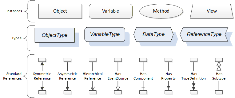
The figures above use a notation that was developed for the OPC UA specification. The notation is summarized in Figure 7. UML representations can also be used; however, the OPC UA notation is less ambiguous because there is a direct mapping from the elements in the figures to Nodes in the address space of an OPC UA server.
A complete description of the different types of Nodes and References can be found in OPC 10000-3 and the base OPC UA Address space is described in OPC 10000-5.
OPC UA specification defines a very wide range of functionality in its basic information model. It is not expected that all Clients or Servers support all functionality in the OPC UA specifications. OPC UA includes the concept of profiles, which segment the functionality into testable certifiable units. This allows the development of companion specification (such as OPC UA for ISA-95) that can describe the subset of functionality that is expected to be implemented. The profiles do not restrict functionality, but generate requirements for a minimum set of functionality (see OPC 10000-7).
The OPC Foundation also defines a set of information models that provide a basic set of functionality. The Data Access specification (see OPC 10000-8) provides a basic information model for typical data. The Alarm and Condition specification (see OPC 10000-9) defines a standard information model for Alarms and Conditions. The Programs specification (see OPC 10000-10) defines a standard information model for extending the functionality available via method calls and state machines. The Historical Access specification (see OPC 10000-11) defines the information model associated with Historical Data and Historical Events. The aggregates specification (see OPC 10000-13) defines a series of standard aggregate functions that allow a Client to request summary data. Examples of aggregates include averages, minimums, time in state, Standard deviation, etc.
4.3.4.2 Namespaces
OPC UA allows information from many different sources to be combined into a single coherent address space. Namespaces are used to make this possible by eliminating naming and id conflicts between information from different sources. Namespaces in OPC UA have a globally unique string called a NamespaceUri and a locally unique integer called a NamespaceIndex. The NamespaceIndex is only unique within the context of a Session between an OPC UA Client and an OPC UA Server. All of the web services defined for OPC UA use the NamespaceIndex to specify the Namespace for qualified values.
There are two types of values in OPC UA that are qualified with Namespaces: NodeIds and QualifiedNames. NodeIds are globally unique identifiers for Nodes. This means the same Node with the same NodeId can appear in many Servers. This, in turn, means Clients can have built in knowledge of some Nodes. OPC UA information models generally define globally unique NodeIds for the TypeDefinitions defined by the information model.
QualifiedNames are non-localized names qualified with a Namespace. They are used for the BrowseNames of Nodes and allow the same names to be used by different information models without conflict. The BrowseName is used to identify the children within a TypeDefinitions. Instances of a TypeDefinition are expected to have children with the same BrowseNames. TypeDefinitions are not allowed to have children with duplicate BrowseNames; however, instances do not have that restriction.
4.3.4.3 Companion Specifications
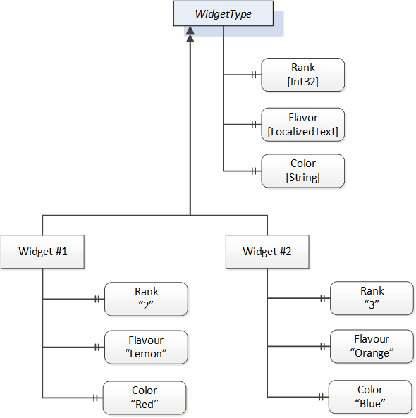
An OPC UA companion specification for an industry specific vertical market describes an information model by defining ObjectTypes, VariableTypes, DataTypes and ReferenceTypes that represent the concepts used in the vertical market. Table 1 contains an example of an ObjectType definition.
| Attribute | Value | ||||
| BrowseName | WidgetType | ||||
| IsAbstract | False | ||||
| Reference | NodeClass | BrowseName | DataType | TypeDefinition | ModellingRule |
|---|---|---|---|---|---|
| Subtype of the BaseObjectType from OPC 10000-5. | |||||
| HasProperty | Variable | Color | String | PropertyType | Mandatory |
| HasProperty | Variable | Flavor | LocalizedText | PropertyType | Mandatory |
| HasProperty | Variable | Rank | Int32 | PropertyType | Mandatory |
The BrowseName is a non-localized name for an ObjectType.
IsAbstract is a flag indicating whether instances of the ObjectType can be created.
The bottom of the table lists the child nodes for the type. The Reference is the type of reference between the Object instance and the child Node. The NodeClass is the class of Node. The BrowseName is the non-localized name for the child. The DataType is the structure of the Value accessible via the Node (only used for Variable NodeClass Nodes) and the TypeDefinition is the ObjectType or VariableType for the child.
The ModellingRule indicates whether a child is Mandatory or Optional. It can also indicate cardinality. Note that the BrowseName is not defined if the cardinality is greater than 1. Figure 8 visually depicts the ObjectType defined in Table 1 along with two instances of the ObjectType.