Ethernet POWERLINK is a communication profile for Real-Time Ethernet (RTE). It extends Ethernet according to the IEEE 802.3 standard with mechanisms to transfer data with predictable timing and precise synchronisation. The communication profile meets timing demands typical for high-performance automation and motion applications. It does not change basic principles of the Fast Ethernet Standard IEEE 802.3 but extends it towards RTE. Thus, it is possible to leverage and continue to use any standard Ethernet silicon, infrastructure component or test and measurement equipment like a network analyser.
POWERLINK provides mechanisms to achieve the following:
- Transmit time-critical data in precise isochronous cycles. Data exchange is based on a publish/subscribe relationship. Isochronous data communication can be used for exchanging position data of motion applications of the automation industry.
- Synchronise networked POWERLINK Devices with high accuracy.
- Transmit less time-critical data asynchronously on request. Asynchronous POWERLINK Data communication can be used to transfer IP-based protocols like TCP or UDP and higher layer protocols such as HTTP, FTP, etc.
POWERLINK manages the network traffic in a way that there are dedicated time-slots for Isochronous and Asynchronous POWERLINK Data. It takes care that always only one networked device gains access to the network media. Thus, transmission of Isochronous POWERLINK Data and Asynchronous POWERLINK Data will never interfere and precise communication timing is guaranteed. The mechanism is called Slot Communication Network Management (SCNM). SCNM is managed by one particular networked device – the POWERLINK Managing Node (MN) – which includes the MN functionality. All other nodes are called POWERLINK Controlled Nodes (CN).
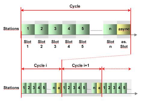
Figure 1 – Slot Communication Network Management (SCNM)
POWERLINK provides the following key features:
Ease-of-Use to be handled by typical automation engineers without in-depth Ethernet network knowledge.
Up to 240 networked real-time devices in one network segment
Deterministic communication guaranteed
Down to 100 μs cycle times
Ultra-low jitter (down to <1μs) for precise synchronisation of networked devices
Standard compliant
IEEE 802.3 Fast Ethernet
IP based protocols supported (TCP, UDP, etc.)
Integration with CANopen profiles EN 50325-4 for device interoperability
Implementation based on standard Ethernet chips - no special ASICs necessary
Direct peer-to-peer communication of all POWERLINK Devices (publish/subscribe)
Hot plugging
Seamless IT-integration – routing of IP protocols
POWERLINK supports Client/Server and Producer/Consumer communication relationships.
The POWERLINK communication profile is based on CANopen communication profiles DS301 and DS302. Based on these communication profiles, the multitude of CANopen device profiles can be used in a POWERLINK environment without changes.
A main focus of POWERLINK is ease of use. Ethernet technology can be quite complex and confusing for machine and plant manufacturers, which are not necessarily networking experts. The following features have thus been implemented:
Easy wiring, flexible topologies (line structures, tree structures or star structures). The network is adapting to the needs of the machine.
Utilisation of well-known industrial infrastructure components
Simple address assignment by switch is possible
Easy replacement of devices in case of failure
Straight-forward network diagnostics
Simple engineering separated from end user IT infrastructure
Easy integration of RTE network with IT infrastructure
A POWERLINK Device is structured as follows (see Figure 2):
Communication – This function unit provides the communication objects and the appropriate functionality to transport data items via the underlying network structure.
POWERLINK Object Dictionary – The POWERLINK Object Dictionary is a collection of all the data items that have an influence on the behaviour of the application objects, the communication objects and the state machine used on this device.
Application – The application comprises the functionality of the device with respect to the interaction with the process environment.
Thus the POWERLINK Object Dictionary serves as an interface between the communication and the application. The complete description of a device’s application with respect to the data items in the POWERLINK Object Dictionary is called the device profile.
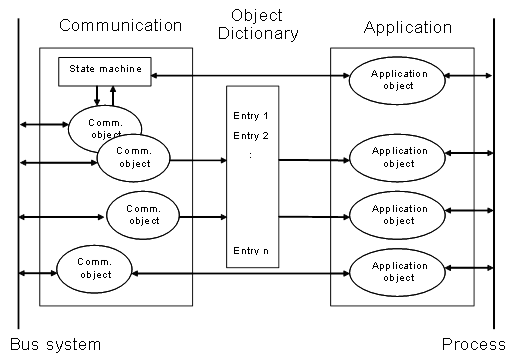
Figure 2 – POWERLINK device model
The most important part of a POWERLINK profile is the POWERLINK Object Dictionary. The POWERLINK Object Dictionary is essentially a grouping of POWERLINK Objects accessible via the network in an ordered, pre-defined fashion. Each object within the dictionary is addressed using a 16-bit index.
The overall layout of the standard POWERLINK Object Dictionary is shown by Table 8. This layout closely conforms to other industrial serial bus system concepts.
The POWERLINK Object Dictionary may contain a maximum of 65536 entries which are addressed through a 16-bit index.
The Static Data Types at indices 0001h through 001Fh contain type definitions for standard data types like BOOLEAN, INTEGER, floating point, string, etc. These entries are included for reference only; they cannot be read or written.
Table 8 – POWERLINK Object Dictionary structure
|
Index |
Object |
|
0000h |
not used |
|
0001h .. 001Fh |
Static Data Types |
|
0020h .. 003Fh |
Complex Data Types |
|
0040h .. 005Fh |
Manufacturer Specific Complex Data Types |
|
0060h .. 007Fh |
Device Profile Specific Static Data Types |
|
0080h .. 009Fh |
Device Profile Specific Complex Data Types |
|
00A0h .. 03FFh |
Reserved for further use |
|
0400h – 041Fh |
POWERLINK Specific Static Data Types |
|
0420h – 04FFh |
POWERLINK Specific Complex Data Types |
|
0500h .. 0FFFh |
Reserved for further use |
|
1000h .. 1FFFh |
Communication Profile Area |
|
2000h .. 5FFFh |
Manufacturer Specific Profile Area |
|
6000h .. 9FFFh |
Standardised Device Profile Area |
|
A000h .. BFFFh |
Standardised Interface Profile Area |
|
C000h .. FFFFh |
Reserved for further use |
Complex Data Types at indices 0020h through 003Fh are pre-defined structures that are composed of standard data types and are common to all devices.
Manufacturer Specific Complex Data Types at indices 0040h through 005Fh are structures composed of standard data types but are specific to a particular device.
Device Profiles may define additional data types specific to their device type. The static data types defined by the device profile are listed at indices 0060h - 007Fh, the complex data types at indices 0080h - 009Fh.
A device may optionally provide the structure of the supported complex data types (indices 0020h - 005Fh and 0080h - 009Fh) at read access to the corresponding index. Sub-Index 0 provides the number of entries at this index, and the following sub-indices contain the data type encoded as UNSIGNED16 according to 7.1 Primitive DataTypes.
POWERLINK Specific Static Data Types shall be described at indices 0400h – 041Fh. These entries are included for reference only; they cannot be read or written. POWERLINK Specific Complex Data Types shall be described at indices 0420h – 04FFh
The Communication Profile Area at indices 1000h through 1FFFh contains the communication specific parameters for the POWERLINK network. These entries are common to all devices and addressed by this companion specification.
A 16-bit index is used to address all entries within the POWERLINK Object Dictionary. In the case of a simple variable, the index references the value of this variable directly. In the case of records and arrays, however, the index addresses the whole data structure.
To allow individual elements of structures of data to be accessed via the network a Sub-Index is defined. For single POWERLINK Object Dictionary entries such as an UNSIGNED8, BOOLEAN, INTEGER32 etc. the value for the Sub-Index is always zero. For complex POWERLINK Object Dictionary entries such as arrays or records with multiple data fields the Sub-Index references fields within a data-structure pointed to by the main index. The fields accessed by the Sub-Index can be of differing data types.