
6 PROFINET GSD Generic Model Information Model overview
6.1 Information Model Creation
The following sequence of steps lays out a general procedure for the creation of a 'generic' Information Model for Devices the Server has access to by PROFINET means:
The Server reads Vendor-ID and Device-ID from the Device.
With Vendor-ID and Device-ID the Server finds the matching GSDML file. The GSDML file must have made accessible for the Server beforehand, see 4.1 also.
The Server reads the "RealIdentificationData" to obtain the IO Data available on the Device.
The Server reads the "ARData" record to obtain a list of all ARs active on the Device, then reads the "ExpectedIdentificationData" record (see [PN PROTOCOL]) for each AR to obtain a list of expected modules and Submodules.
For each Submodule found in the "RealIdentificationData" and the "ExpectedIdentificationData" records, the Server creates GsdGenSubmoduleApplicationType Objects in the Information Model accordingly (see 6.3). Missing Submodules (SubmoduleState.IdentInfo block contains "NoSubmodule") shall not be represented in the Information Model.
If the "ModuleDiffBlock" for each AR is empty or has a SubmoduleState.IdentInfo block containing "Substitute" or "OK" for the Submodule, the Submodule shall be represented with the CommunicationStatus Property set to INDATA (see 7.1) in the Information Model. If the SubmoduleState.IdentInfo block indicates a configuration mismatch for a Submodule ("Wrong"), it shall have the CommunicationStatus Property set to OFFLINE.
The ConfigurationStatus Property (see 7.1) is set to WRONG or SUBSTITUTE according to the content of the SubmoduleState.IdentInfo block. If the ModuleDiffBlock is empty or the SubmoduleState.IdentInfo block contains "OK", the ConfigurationStatus Property shall be set to OK.
Submodules found in the "RealIdentificationData" record which are not part of a configured AR (are not found an a "ExpectedIdentificationData" record) shall be represented with the CommunicationStatus Property set to OFFLINE and the ConfigurationStatus Property set to UNKNOWN.
The ARIdentifier Property (see 7.1) shall be provided for each Submodule belonging to an AR which is "InData".
The Server learns the structure of each represented Submodule's IO Data by reading the corresponding "(Virtual)SubmoduleItem/IOData" elements in the GSDML file and creates the GsdGenIoDataType Objects and their components representing the IO Data of the Submodule (see 6.3 and 6.4).
The Server evaluates the child-elements of the Submodule's "RecordDataList" element referencing the "ParameterRecordDataItem" elements describing the parameterization records of the Device and creates Variables in the Information Model accordingly (see 6.6).
The Server evaluates the child-elements of the Submodule's "AvailableRecordDataList" element referencing the "ParameterRecordDataItem" elements describing the Data Objects offered by the Device and creates Variables in the Information Model accordingly (see 6.7).
The Server might also find a "PROFIenergy" element (see [GSDML]). The Server shall evaluate the structure inside this element and build a PROFIenergy Information Model using the PESAP as defined in [OPC PE].
6.2 Application Object
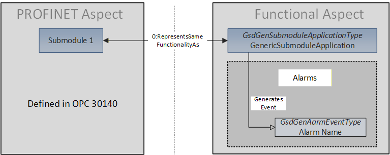
The GsdGenSubmoduleApplicationType is the root container for modelling of the Information Model belonging to one PN Submodule and relates to the PN Submodule Object with a 0:RepresentsSameFunctionalityAs ReferenceType. There shall be as many GsdGenSubmoduleApplicationType Objects as there are PN Submodules found on the Device.
The GsdGenSubmoduleApplicationType Object aggregates the representation of the elements found in the GSDML file. As specified in [OPC RIO], the Information Model is divided into a PROFINET aspect and a functional aspect. The PROFINET aspect offers detailed Telegram information (see [OPC RIO]), the functional aspect contains the generic Information Model by providing GsdGenSubmoduleApplicationType Objects. The Signal Objects (see [OPC RIO]) in the PROFINET aspect relate to components of the GsdGenIoDataType Objects in the functional aspect by dedicated 0:RepresentsSameEntityAs References.
The components of the GsdGenSubmoduleApplicationType are separated into four sub-aspects as shown in Figure 6.
The "IO Data" sub-aspect contains the generic IO Data mapping derived from the GSDML "(Virtual)SubmoduleItem/IOData" element.
The "Parameters" sub-aspect contains the generic Parameter record mapping from the GSDML "(Virtual)SubmoduleItem/RecordDataList" element. The "ParameterRecordDataRef" elements in this list refer to Parameter records described by "ParameterRecordDataItem" elements belonging to an API defined in the GSDML file.
The "Data Objects" sub-aspect contains the generic Data Object mapping from the GSDML "(Virtual)SubmoduleItem/AvailableRecordDataList" element. The "RecordDataRef" elements in this list refer to Data Objects described by "ParameterRecordDataItem" elements belonging to an API defined in the GSDML file. There may also exist a mapping of Parameters obtained using BMP Access.
The "Alarms" sub-aspect contains the generic Alarm data mapping from the various GSDML elements describing Alarms. The Server may generate Events containing Alarm data.
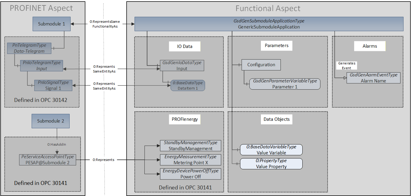
There may exist a "PROFIenergy" element for a Submodule in the GSDML. In this case a "PROFIenergy" sub-aspect containing the PROFIenergy Information Model as specified in [OPC PE is created. The PROFIenergy model directly relates to the Submodule Object in the PROFINET Aspect using a 0:HasAddIn ReferenceType and has no connection with a GsdGenSubmoduleApplicationType Object.
6.3 IO Data
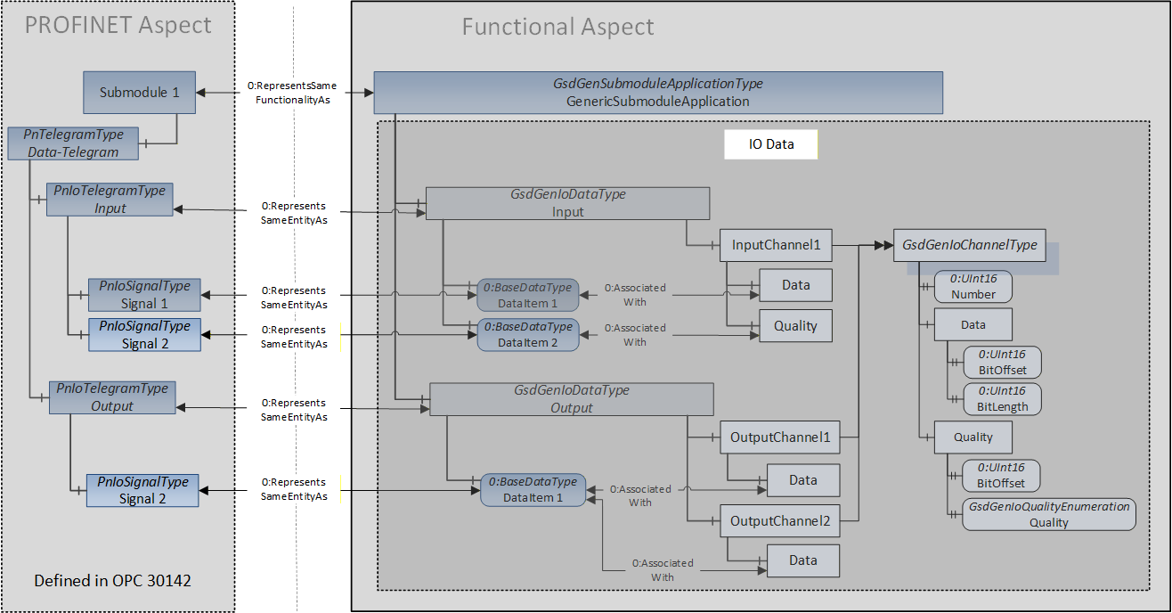
Figure 7 shows an IO Data model to demonstrate the basic principle of the relationships of the Objects in the PROFINET Aspect with the Objects and Variables representing IO Data in the Functional Aspect of the Information Model.
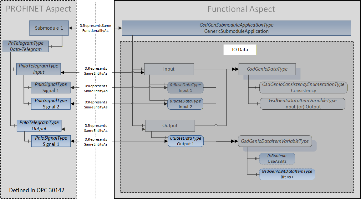
The "Submodule 1" Object in the PROFINET Aspect relates to the GsdGenSubmoduleApplicationType Object using a 0:RepresentsSameFunctionalityAs ReferenceType. The GsdGenIoDataItemVariableType Variables relate to the Signal Objects representing IO Data in the PROFINET Aspect using a 0:RepresentsSameEntityAs ReferenceType.
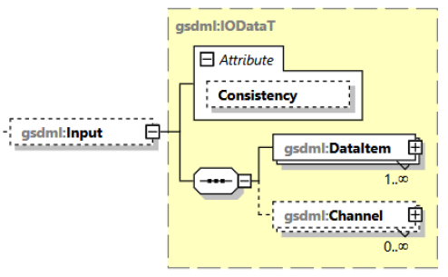
The IO Data is described using "DataItem" elements. In particular, the "DataItem" elements define the data types used and therefore together determine the size and layout of the memory allocated for IO Data (see [GSDML], 8.12 for a thorough description). Figure 9 shows the XML schema of the "DataItem" XML element.
If the "DataType" attribute describes an unsigned numeric data type or an "OctetString", the optional "UseAsBits" attribute may be present and set to "true" (see description of "UseAsBits" attribute in [GSDML], 8 ff.). The optional "BitDataItem" elements are present in this case and the definition of individual bits inside the DataItem data type.
If the "Subordinate" attribute is present (only allowed for "Input/DataItem" elements) and set to "true", the IO Data of the Submodule must be organized according to rules defined by RIOforFA (see [RIO FA]).
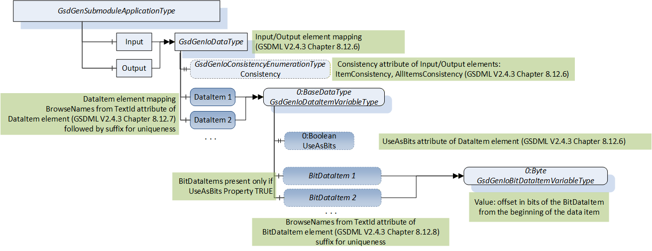
Figure 10 shows the mapping of the XML elements describing the IO Data to the representing Objects and Variables in the Information Model.
The GsdGenIoDataType represents the mapping of the content of the GSDML "Input" and "Output" child elements of the "IOData" element. For a detailed description see 7.2 and 9.1.
6.4 IO Channel
Figure 11 shows the "IO Data" Sub-Aspect in the Functional Aspect of the Information Model.
The GsdGenIoDataType Objects relate to the associated GsdGenIoChannelType Objects using the 0:HasComponent ReferenceType. The "Data" components of the GsdGenIoChannelType Objects relate to the data item elements representing the channel data using 0:AssociatedWith ReferenceTypes. The optional "Quality" component relates to the data item representing the part of the IO Data which contains the qualifier information of the respective channel. The "Data" components of the "OutputChannel1" and "OutputChannel2" Objects refer to the same data item ("Data Item 1").
Each channel specified has a unique channel number defined by the "Number" attribute. The mandatory "Data" element's attribute "BitOffset" (not shown in the figure) specifies an offset into the "DataItem" / "BitDataItem" elements and points to the start of the channel data. The channel data may be defined by a single "DataItem" element or by a sequence of consecutive "DataItem" elements. The BitOffset may point into a data item also (see channel "Data" element specification in [GSDML], 8 ff.). The mandatory "BitLength" attribute specifies the length of the channel data.
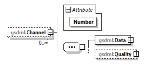
Figure 13 shows the mapping of the "Channel" elements and its child elements to Objects in the Information Model.
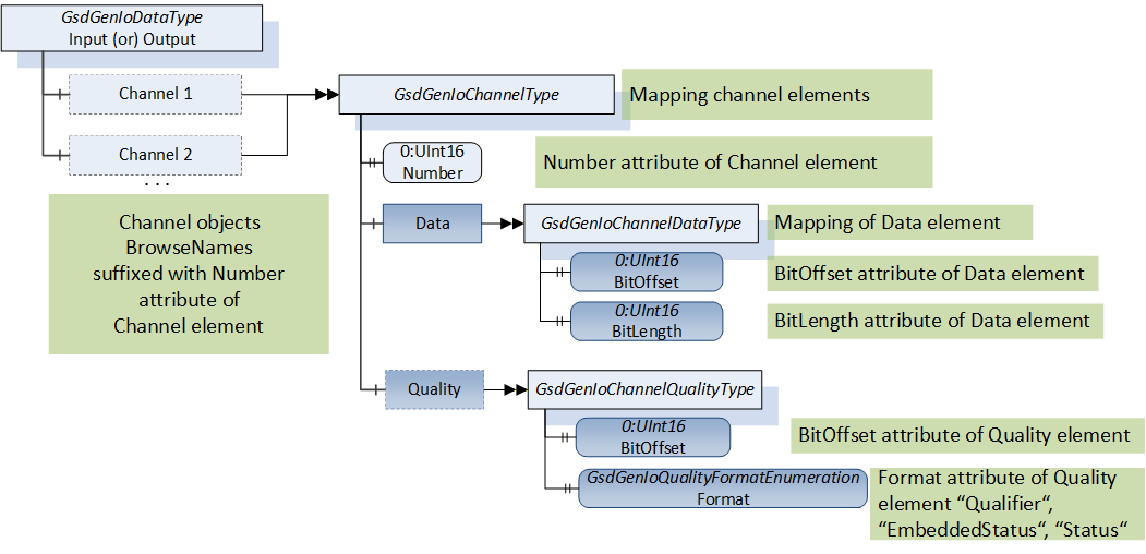
The BitOffset Property of the optional "Quality" Object points to the start of the channel quality data. This offset into the data may point into a data item also (no separate data item for quality information, see channel "Quality" element specification in [GSDML] chapter 8 ff.). The "Data" and the "Quality" components of the GsdGenIoChannelType Object are associated with the same data item using 0:AssociatedWith ReferenceTypes in this case.
The "Format" Property defines the size and layout of the quality information (see "Quality" element specification in [GSDML], 8 ff.).
6.5 IO Data Qualifier and StatusCode Relationship
If quality data is provided (see GsdGenIoChannelQualityType), the Server shall set the StatusCode member of the DataValue structures returned by the Read Service and the Publish Service consistent with the content of the quality data when returning the Value of GsdGenIoDataItemVariableType Variables representing IO Data.
The quality data format is specified by the Value of the Format Property of the GsdGenIoChannelQualityType Object. Dependent on the quality data format, the Server shall set the StatusCodes as specified in Table 16.
| Format Property Value | StatusCode |
| QUALIFIER | Set StatusCode as defined in [OPC RIO], sec. 6.8.2 Table 16 "RIOforFA StatusCodes" |
| EMBEDDED_STATUS | Set StatusCode as defined in [RIOforPA] sec. 4.1 "Status Information", see Table 17 also. |
| STATUS | Set StatusCode as defined in [OPC RIO], sec. 6.8.1.2 Table 14 "Condensed status with detailed information" |
If the "DataType" attribute of the "DataItem" element (see [GSDML]) specifies a data type with embedded status bits (see Table 58, "Unsigned16_S", "Integer16_S", "Unsigned8_S", "OctetString_S"), the Server shall set the StatusCode according to Table 17. The Value of the representing Variable in the Information Model shall not contain the status bits.
| Status Bits | StatusCode |
| 00 ('B') | Bad (0x80000000) |
| 01 ('S') | GoodEdited (0x00DC0000) |
| 10 ('U') | Uncertain (0x40000000) |
| 11 ('G') | Good (0x00000000) |
6.6 Parameters
Figure 14 shows the "Parameters" sub-aspect in the Functional Aspect of the Information Model.
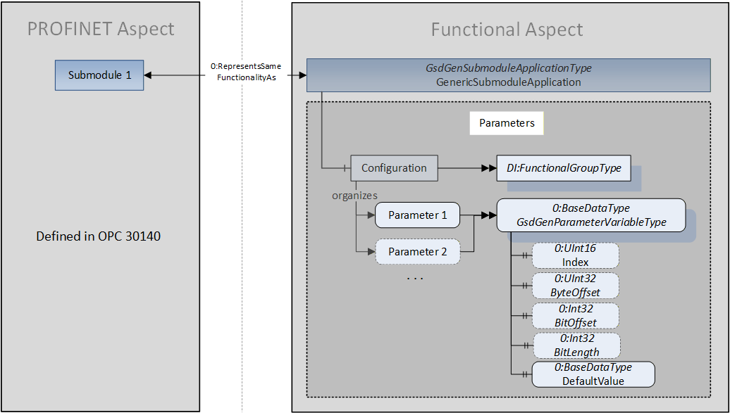
The GsdGenParameterVariableType Variable represents one Parameter as part of a parameter record described by the "ParameterRecordDataItem" element in the GSDML. Each GsdGenParameterVariableType Variable shall be part of the "Configuration" folder. The optional Index Property contains the PROFINET record number used to read the parameter record from the Device. The "Configuration" folder Object references as many GsdGenParameterVariableType Variables as there are separate Parameter values in the Parameter records referenced by the associated Submodule. The modelling of the Parameters as Variables allows Clients to obtain the Parameters without dissecting the Parameter record structure. Figure 15 shows the schema of the GSDML "ParameterRecordDataItem" elements describing Parameter records.
The Server shall use the "Index" attribute of the "ParameterRecordDataItem" element to read the actual value of the parameter record from the Device. The Server shall then use the attributes of the "Ref" elements describing single Parameters to obtain the values needed to create the GsdGenParameterVariableType Variables.
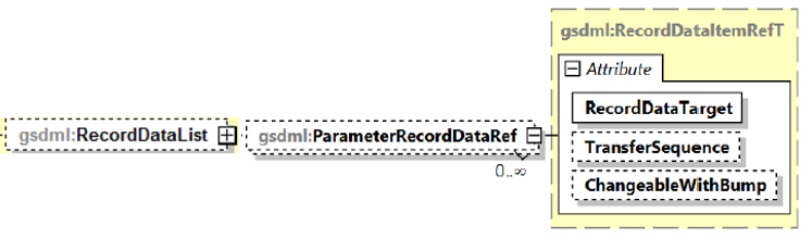
Only Parameters described by "ParameterRecordDataItem" elements contained in the "ApplicationProcess/RecordDataList" shall be represented in the Information Model. These "ParameterRecordDataItem" elements are referenced by "(Virtual)SubmoduleItem /RecordDataList/ParameterRecordDataRef" elements (see Figure 16 and [GSDML], 8.15.9).
Since only Parameter records readable from the Submodule are allowed (see above), the referenced "ParameterRecordDataItem" elements shall have an "Access" attribute containing at least the "prm" and the "read" tokens. Elements describing Parameter records which cannot be read from the Submodule shall not be referenced.
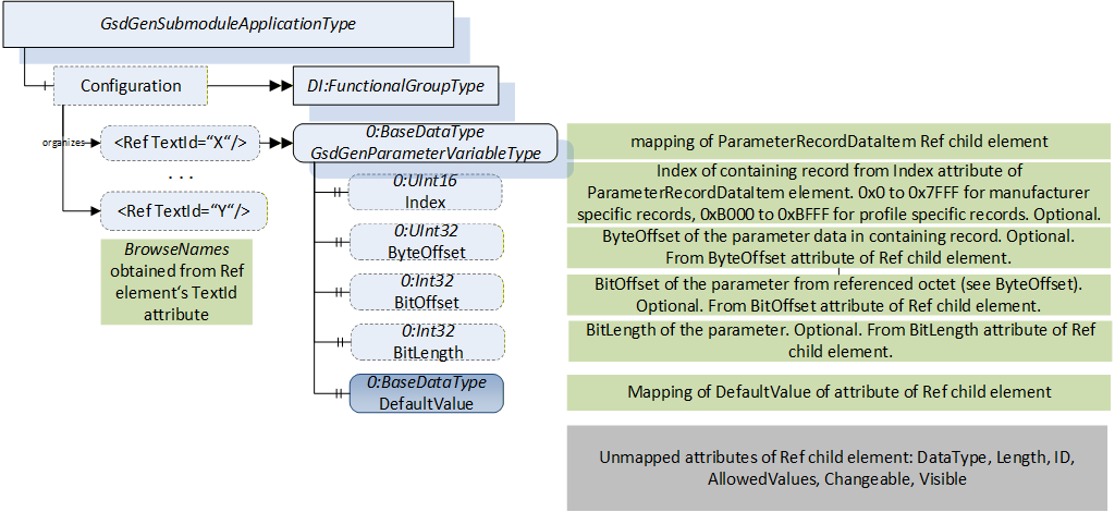
Figure 17 shows the mapping of the "ParameterRecordDataItem" elements and their "Ref" child elements to Variables and Properties in the Information Model. The "Const", "MenuList", "RefMeta" and "RecordMeta" elements are not used as well as most attributes of the "Ref" element.
The Server shall provide the "Configuration" folder Object only if there are readable Parameter records specified in the GSDML for the Submodule.
6.7 Data Objects
Figure 18 shows the "Data Objects" sub-aspect in the Functional Aspect of the Information Model.
This aspect contains additional data values modelled as Variables or Properties for one Submodule if the GSDML contains a "(Virtual)SubmoduleItem/AvailableRecordDataList".
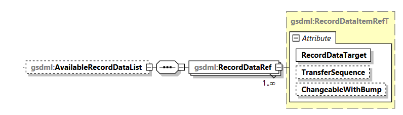
Figure 19 shows the schema of the "AvailableRecordDataList" XML elements in the GSDML. The "AvailableRecordDataList" element contains "RecordDataRef" elements referencing "ParameterRecordDataItem" elements in the "ApplicationProcess/RecordDataList" (see [GSDML], 8.9.4).
The record must be readable from the referencing Submodule with the record index found in the "Index" attribute of the "ParameterRecordDataItem" element. Vendors might allow write access also using the "Access" attribute of the "ParameterRecordDataItem" element (see [GSDML]). Elements used for parameterization ("Access" attribute contains "prm" or is not present) represent Parameter records (see 6.6) and are not represented as Data Objects.
Additional properties needed for Data Objects are described by "RefMeta" and "RecordMeta" child elements of the "ParameterRecordDataItem" elements. Figure 20 shows the XML schema defined for the "RefMeta" and "RecordMeta" elements.
The "MetaExtensionT" schema describes a way to enhance certain elements in the GSDML with content which is defined in a different specification. For the description of Data Objects, the "Ref" elements may be extended with a "RefMeta" child element. The "RefMeta" element shall have a "Prefix" attribute and "Meta" child elements as shown in the following XML snippet.
<RefMeta Prefix="<tag> <URI>">
	<Meta Property="tag:<property name>" Content="<property content>"/>
		...
</RefMeta>
The content of the "Prefix" attribute of the "RefMeta" element defines a tag name and the URI of the specification responsible for the definition of the required content of "Meta" child elements. The tag is used as prefix for the content of the "Property" attribute of all "Meta" child elements which are defined by the associated specification (see [GSDML], 8.28.1 "MetaExtension").
Annex C describes the required attributes of the "RefMeta" and "Meta" child elements describing a Data Object.
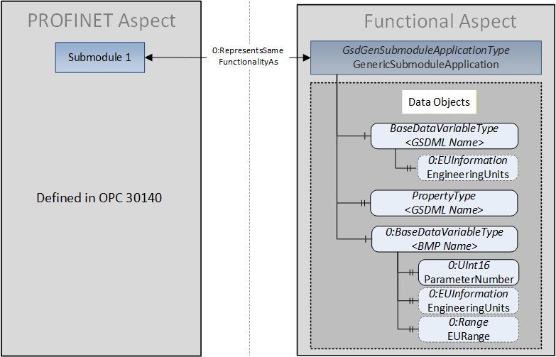
The Object representing the Submodule offering Data Objects in the PROFINET aspect of the Information Model relates to the GsdGenSubmoduleApplicationType Object providing the Variables and Properties for these Data Objects using the 0:RepresentsSameFunctionalityAs ReferenceType.
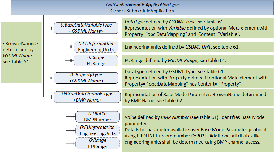
Figure 21 shows the mapping of "ParameterRecordDataItem" elements, their "Ref" and "RefMeta" child elements to Variables in the Information Model.
The default VariableType for representing parameters obtained using Base Mode Parameter Access shall be 0:BaseDataVariableType. The Base Mode Parameter (BMP) data record is specified using a "RecordMeta" child element of the "ParameterRecordDataItem" element. The individual BMPs and their representation in the Information Model are specified using RefMeta elements, see C.2 for details.
Additional Properties shall be created according to the parameter description obtained using BMP Access. The BMP Name (see Table 65) shall be used as BrowseName. See 7.1 for a detailed description.
6.7.1 BMPs with assigned text array
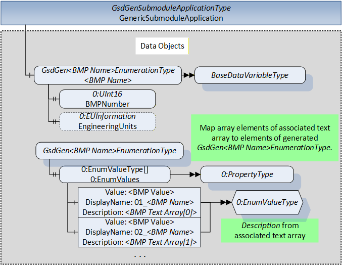
"Simple" BMPs with assigned text array (see [PDP], 6.2.1.4) can be represented by a 0:Enumeration DataType created by the Server, as shown in Figure 22. The array elements are assigned to the fields of the 0:EnumValueType structure as specified in Table 20. The representing Variable shall have the TypeDefinition 0:BaseDataVariableType and the Value shall have the 0:Enumeration DataType created as described above. The BMP Name (see Table 65) shall be used as part of the BrowseName, see 7.1, EnumerationVariable.
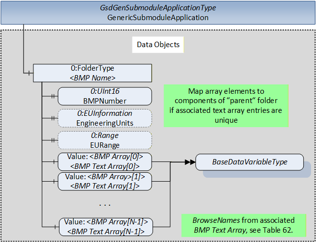
"Array" BMPs with assigned text array (see [PDP], sec. 6.2.1.4) can be represented by a folder Object with Variables as components, as shown in Figure 23. The BMP Name (see Table 65) shall be used as BrowseName of the parent folder Object. If the BMP has assigned engineering units and range, the folder Object shall have a 0:EUInformation and a 0:Range Property. The elements of the assigned text array shall be used as BrowseNames of the 0:BaseDataVariableType Variables representing the array elements. There shall be as many Variables as are needed to represent all array elements. Each Variable Value receives the array element value which has the same index as the assigned text array element which is used as BrowseName.
The intended usage of folder Objects is the representation of "small" array BMPs with assigned text array if the sequence is not of importance. This allows Clients to access array elements in the same way as elements of associative arrays using the assigned texts, since an array element is selected by a text identifier. For example, the first element would have the BrowsePath "<BMP Name>/<BMP Text Array[0]>".
Vendors can specify the desired representation of BMPs by providing "Meta" elements in the GSDML, as described in C.2. See the description of the <EnumerationVariable>, <OptionSetVariable> and <ArrayFolder> placeholders in 7.1 for details.
6.8 Data Object Qualifier and StatusCode Relationship
If the value of the "Ref" element's "DataType" attribute identifies a data type with appended status byte (see Table 58, "Unsigned16_S", "Integer16_S", "Unsigned8_S", "OctetString_S"), the Server shall set the StatusCode according to Table 17. If BMP Access fails for a parameter (request response of BMP Access returns error value, see [PDP], 6.2.3), the Server shall set the StatusCode to "Bad" (0x80000000).
6.9 Function Groups
Determined by "Meta" elements with Property="opc:FunctionGroupName" describing Data Objects the Variables and Properties may be organized as components of 2:FunctionalGroupType folder Objects. If the "Meta" elements with this attribute are missing, the Variables and Properties shall be organized as components at root level of the GsdGenSubmoduleApplicationType Object.
Figure 24 shows the usage of 2:FunctionalGroupType Objects as folders organizing the Data Objects.
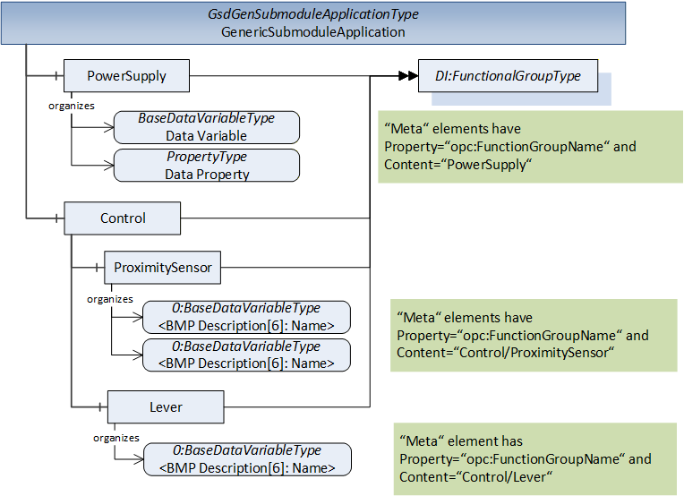
The "FunctionGroupName" property may define a hierarchical folder structure using file system path syntax: "RootFolder/SubFolder/…/Folder". The vendor shall provide path syntax strings yielding a consistent tree structure, as shown in Figure 24. See sample XML in Annex E.1 also.
6.10 Alarms
A Server supporting the "Alarms" sub-aspect shall detect the Alarms generated by the Devices (using PROFINET access) and generate GsdGenAlarmEventType Events. The Events are available for Subscription directly at the GsdGenSubmoduleApplicationType Object, as shown in Figure 25.
Servers providing GsdGenAlarmEventType Events shall read the "DiagnosisData" record to obtain the Alarm data. When processing the alarm data, the Server shall look up describing texts and help texts by evaluating the corresponding XML element.
The Server shall evaluate the "ChannelProcessAlarmList" GSDML element and its "ChannelProcessAlarmItem", "SystemDefinedChannelProcessAlarmItem" and "ProfileChannelProcessAlarmItem" child elements. Figure 26 shows the GSDML structure of the "ChannelProcessAlarmList" child element of the "ApplicationProcess" element (see [GSDML], 8.9.7 ChannelProcessAlarmList).
6.11 Security
Servers shall allow the invocation of the SetApplicationTag Method only for Sessions of user accounts to which the right for Method invocation is explicitly granted. There shall exist user accounts with restricted rights (that is, no Method invocation) for Clients performing data acquisition or diagnosis also.
If well-known Roles are supported by the Server, role-based security (see [OPC 10000-18]) shall be applied. Method invocation shall only be possible if the well-known "Operator" Role is granted to the Client's Session.
All Variables are read-only. Modifying the content of Variables shall only be possible by invoking a "Set-" Method.