
6 OPC UA for PROFINET Encoder Information Model overview
6.1 Introduction to OPC UA for PROFINET Encoder
The PROFINET Encoder Information Model aims to offer Clients Objects and Services based on the Encoder Profile as defined in [ENCP]. The Information Model defined in this specification can also be seen as an extension of the OPC UA for RIO Information Model as defined in [OPC RIO].
OPC UA for PROFINET Encoder consists of all Objects and types provided by an OPC UA Server allowing OPC UA Clients to access data and services of Encoder Objects. As specified in [OPC RIO], the Information Model is divided into a PROFINET aspect and a functional aspect. The PROFINET aspect offers detailed Telegram information (See [OPC RIO]), the functional aspect provides an Information Model for Encoder Objects by providing EncoderChannelType Objects. The Signal Objects (See [OPC RIO]) in the PROFINET aspect are connected with components of the Encoder Objects in the functional aspect by dedicated 0:RepresentsSameEntityAs References.
The EncoderChannelType serves as the root container for modelling of Encoder Objects. The functional aspect with PROFINET Encoder contains as many EncoderChannelType Objects as needed to represent the Encoder Objects of the P-Device. The components of the EncoderChannelType are separated into five different sub-aspects as shown in Figure 9.
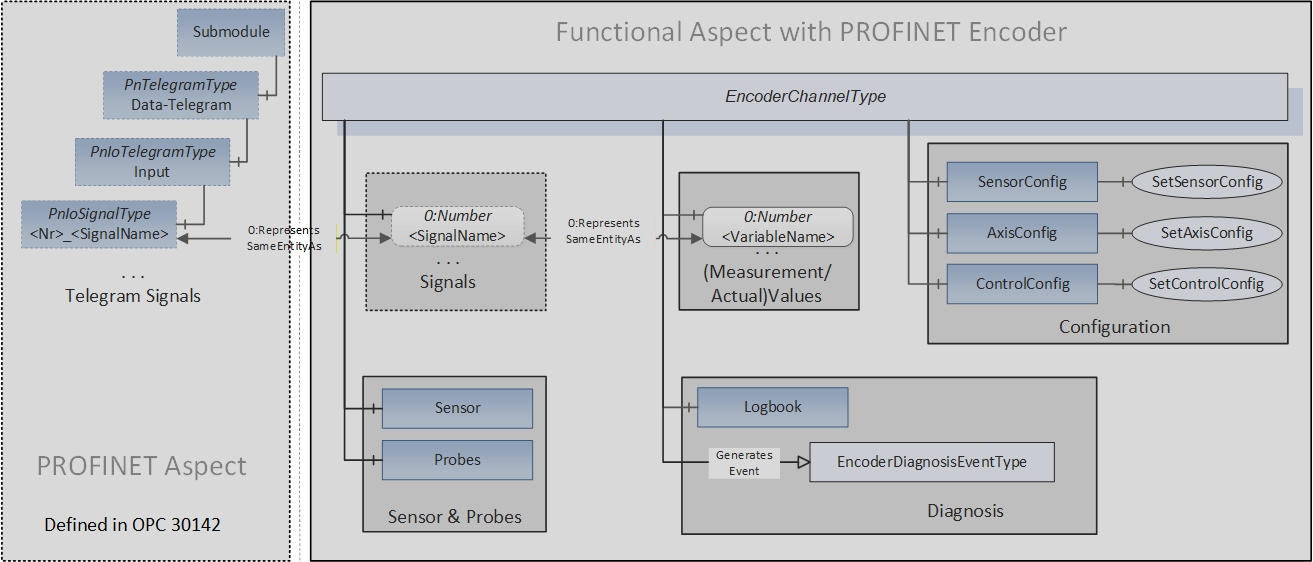
The “Signals” sub-aspect contains the Variables representing the Signal as transmitted in the PROFINET Telegram as Value.
In contrast, the “Measurement/Actual Values” sub-aspect is mainly consisting of Variables which contain the measurement values like position and velocity encoded as numeric data types. If containing information of the same Signal, Variables of these two sub-aspects may also be connected using the 0:RepresentsSameEntityAs Reference type.
The “Configuration” sub-aspect contains Objects holding configuration settings of the Encoder Object. There are also Methods available allowing Clients changing certain settings (See chapters 7.6, 7.7 and 7.8).
The “Sensor & Probes” sub-aspect gives access to sensor and probe data of the Encoder Object by providing the “Sensor” and “Probe” Objects. These Objects offer Variables, Methods, and Events for detailed control and information (See chapters 7.2 and 7.3).
The “Diagnosis” sub-aspect gives Clients access to the content of the Encoder Object’s fault buffer. The Logbook ObjectType provides information about present and transient error conditions (See chapter 7.5). The “Diagnosis” sub-aspect also provides the EncoderDiagnosisEventType offering fault and warning information information.
6.2 Encoder Channel Signals and Measurements
Figure 10 shows a reduced Encoder model with the relationship of the Signal Objects in the PROFINET aspect with the Variables providing concrete Values in the functional aspect. The figure shall give a basic understanding by demonstrating the model organization using three Standard Signals transmitted with Standard Telegram 89 (See [ENCP], chapter 5.6.2).
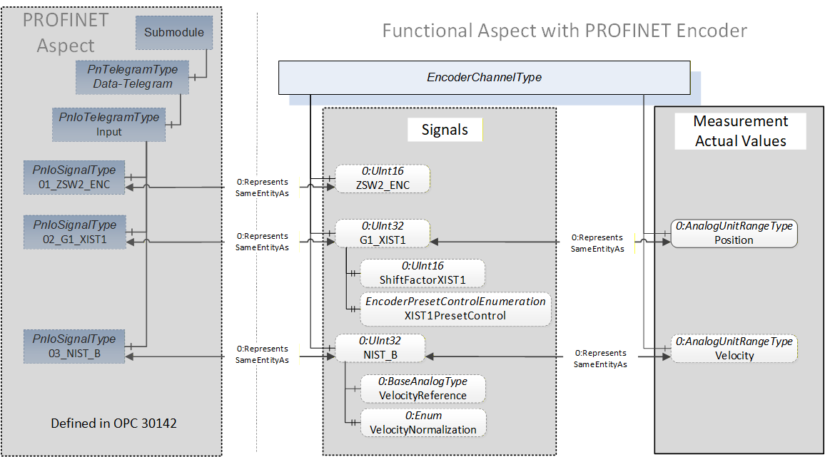
The “Position” and “Velocity” 0:AnalogUnitRangeType Variables in the “Measurement / Actual Values” sub-aspect contain the numeric representation of the “speed” and “position” Standard Signals (See [ENCP] Table 13) allowing Clients easy access to the numeric values of the represented Signals. These Variables are linked to their Signal Variable counterpart in the “Signals” sub-aspect using 0:RepresentsSameEntityAs References.
The “01_ZSW2_ENC”, “02_G1_XIST1” and “03_NIST_B” Signal Objects represent Standard Signals provided by an Encoder Object. These Standard Signals are linked to their counterpart Variables in the functional aspect of the Information Model using 0:RepresentsSameEntityAs References.
The “ZSW2_ENC”, “G1_XIST1” and “NIST_B” Variables in the “Signals” sub-aspect provide the raw Signal Values encoded as unsigned integer data types. Optional Properties of the G1_XIST1 and “NIST_B” Variables provide further Properties like “ShiftFactorXIST1” enabling Clients to gain additional understanding without dissecting all individual Signal bits.
6.3 Encoder Channel Configuration
Figure 11 shows the structure of the “Configuration” sub-aspect.
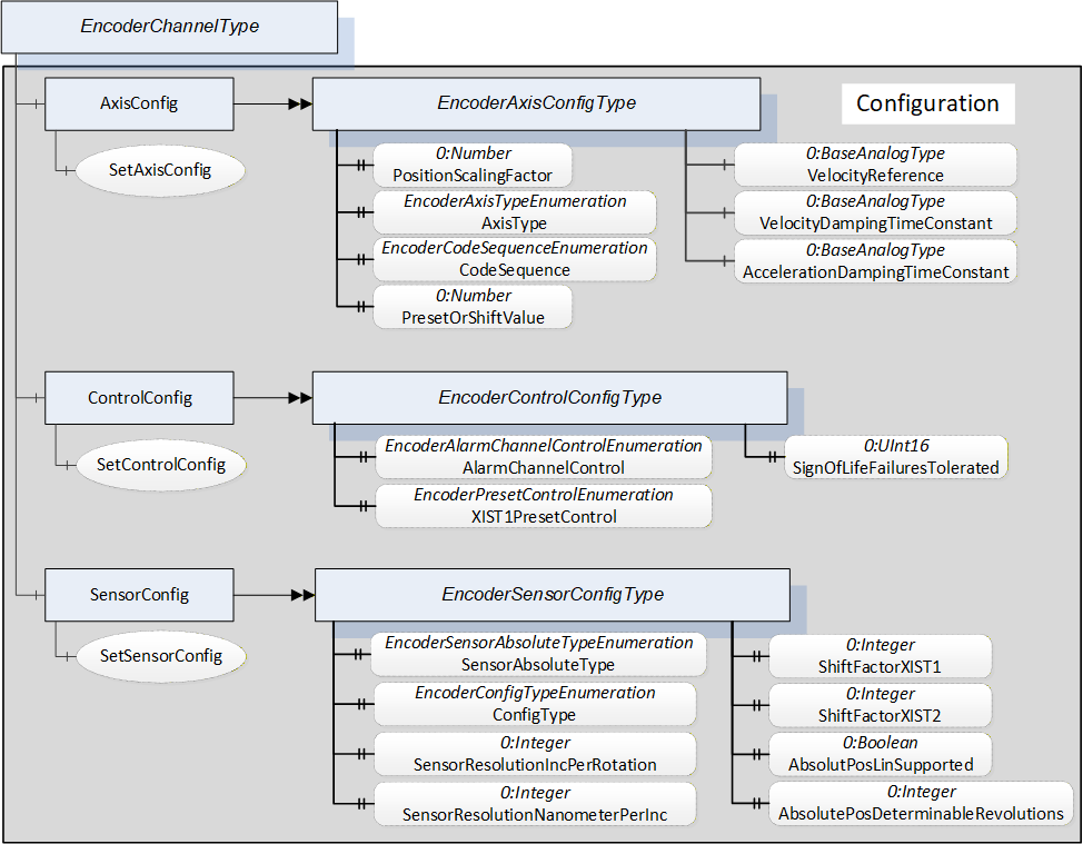
The “Configuration” sub-aspect contains different configuration ObjectTypes and associated Methods for configuration changes.
The AxisConfig EncoderAxisConfigType Object contains configuration Properties belonging to the Encoder’s axis and scaling functions. The SetConfigAxis Method allows changes of certain Properties (Server dependent).
The ControlConfig EncoderControlConfigType Object contains Properties for configuring the alarm channel, the effect of preset functions and the tolerated Sign-Of-Life failures. The SetConfigControl Method allows changes of certain Properties (Server dependent).
The SensorConfig EncoderSensorConfigType Object contains configuration Properties related to the Encoder’s sensor properties and settings. The SetConfigSensor Method allows changes of certain Properties (Server dependent).
6.4 Encoder Channel Sensor & Probes
Figure 12 shows the structure of the “Sensor & Probes” sub-aspect.

The EncoderSensorType Object offers Encoder sensor related Variables. This component of the EncoderChannelType Object also offers Methods for preset control and latch functionality.
The EncoderProbesType Object allows access to probe related functionality of the Encoder Object. Each probe is represented by an EncoderProbeType Object. The EncoderProbeType offers Variables and Methods allowing Clients to start the latch function and to obtain latch state and latch position values.
The “Sensor” and the “Probe1” Objects also generate EventTypes providing information about latch activity and latch position: EncoderRefLatchEventType and EncoderProbeLatchEventType.
6.5 Encoder Channel Diagnosis
Figure 13 shows the structure of the “Diagnosis” sub-aspect.
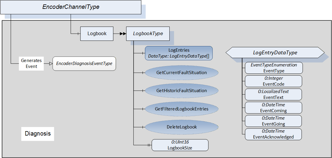
The “Diagnosis” sub-aspect consists of the “Logbook” Object- and EventTypes offering diagnosis related information.
The LogbookType ObjectType mainly consists of an array of LogEntryDataType structures. The size of the array is always given by the LogbookSize Property. There are additional optional Methods for gaining access to filtered subsets of the logbook and clearing the logbook content.
The LogEntryDataType structure has fields for classification of the event. The EventCode field contains an error number (See Table 69 fault codes), the EventType field classifies the error condition into categories like warning or fault. The EventText field contains a brief description of the event. The EventComing and EventGoing time stamp fields indicate the appearance and the disappearance times of the event.
6.6 Encoder Security
Servers shall allow Method invocation only for Sessions using user accounts with the right to invoke the Encoder Methods. There shall exist user accounts with restricted rights (that is, no Method invocation unless explicitly allowed for all users for a specific Method) for Clients performing data acquisition or diagnosis also.
If well-known Roles are supported by the Server, role-based security (see [OPC 10000-18] shall be applied. Method invocation shall only be possible if the well-known “Operator” Role is granted to the Client’s Session. This applies to all Methods except for those where the restriction is lifted explicitly.
All Variables are read-only. Modifying the content of Variables shall only be possible by invoking a “Set-” Method.