4 General information to IEC 61131-3 and OPC UA
4.1 Introduction to IEC 61131-3
IEC 61131-3 is the first real endeavour to standardize programming languages for industrial automation. With its worldwide support, it is independent of any single company.
IEC 61131-3 is the third part of the IEC 61131 family. This consists of: (1) General information, (2) Equipment requirements and tests, (3) Programming languages, (4) User guidelines, (5) Communications, (6) Safety, (7) Fuzzy control programming, and (8) Guidelines for the application and implementation of programming languages.
IEC 61131-3 basically describes the Common Elements and Programming Languages.
4.1.1 Common Elements
4.1.1.1 Data Typing
Within the common elements, the data types are defined. Data typing prevents errors in an early stage. It is used to define the type of any parameter used. This avoids for instance dividing a Date by an Integer.
Common data types are Boolean, Integer, Real and Byte and Word, but also Date, Time_of_Day and String. Based on these, one can define own personal data types, known as derived data types. In this way one can define an analogue input channel as data type, and re-use this over and over again.
4.1.1.2 Ctrl Variables
Ctrl Variables are only assigned to explicit hardware addresses (e.g. input and outputs) in Ctrl Configurations, Ctrl Resources or Ctrl Programs. In this way a high level of hardware independency is created, supporting the reusability of the software.
The scopes of the Ctrl Variables are normally limited to the organization unit in which they are declared, e.g. local. This means that their names can be reused in other parts without any conflict, eliminating another source of errors. If the Ctrl Variables should have global scope, they have to be declared as such (VAR_GLOBAL). Ctrl Variables can be assigned an initial value at start up and cold restart, in order to have the right setting.
4.1.1.3 Ctrl Configuration, Ctrl Resources and Ctrl Tasks
These elements are integrated within the software model as defined in the standard (see below).
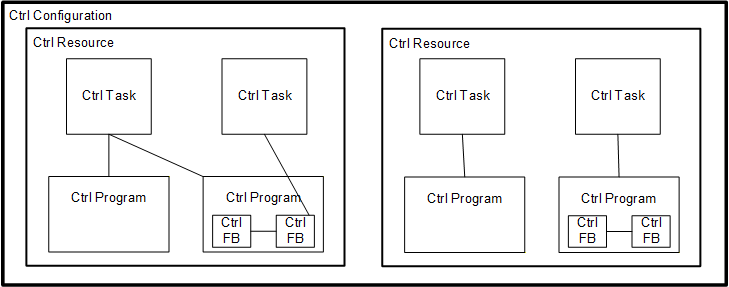
At the highest level, the entire software required to solve a particular control problem can be formulated as a Ctrl Configuration. A Ctrl Configuration is specific to a particular type of control system, including the arrangement of the hardware, i.e. processing resources, memory addresses for I/O channels and system capabilities.
Within a Ctrl Configuration one can define one or more Ctrl Resources. One can look at a Ctrl Resource as a processing facility that is able to execute IEC 61131-3 Ctrl Programs.
Within a Ctrl Resource, one or more Ctrl Tasks can be defined. Ctrl Tasks control the execution of a set of Ctrl Programs and/or Ctrl Function Blocks. These can either be executed periodically or upon the occurrence of a specified trigger, such as the change of a Ctrl Variable.
Ctrl Programs are built from a number of different software elements written in any of the IEC 61131-3 defined programming languages. Typically, a Ctrl Program consists of a network of Ctrl Functions and Ctrl Function Blocks, which are able to exchange data. Ctrl Functions and Ctrl Function Blocks are the basic building blocks, containing a data structure and an algorithm.
4.1.1.4 Ctrl Program Organization Units
Within IEC 61131-3IEC 61131-3, the Ctrl Programs, Ctrl Function Blocks and Ctrl Functions are called Ctrl Program Organization Units, POUs.
4.1.1.5 Ctrl Functions
IEC 61131-3IEC 61131-3 has defined standard Ctrl Functions and user defined Ctrl Functions. Standard Ctrl Functions are for instance ADD(addition), ABS(absolute), SQRT, SIN(sinus) and COS(cosinus). User defined Ctrl Functions, once defined, can be used over and over again.
4.1.1.6 Ctrl Function Blocks
Ctrl Function Blocks are the equivalent to integrated circuits, representing a specialized control function. They contain data as well as the algorithm, so they can keep track of the past (which is one of the differences w.r.t. Ctrl Functions). They have a well-defined interface and hidden internals, like an integrated circuit or black box. In this way they give a clear separation between different levels of programmers, or maintenance people.
A temperature control loop, or PID, is an excellent example of a Ctrl Function Block. Once defined, it can be used over and over again, in the same Ctrl Program, different Ctrl Programs, or even different projects. This makes them highly re-usable.
Ctrl Function Blocks can be written in any of the IEC 61131-3 languages, and in most cases even in "C". This way they can be defined by the user. Derived Ctrl Function Blocks are based on the standard defined Ctrl Function Blocks, but also completely new, customized Ctrl Function Blocks are possible within the standard: it just provides the framework.
The interfaces of Ctrl Functions and Ctrl Function Blocks are described in the same way.
4.1.1.7 Sequential Function Chart
Within the standard Sequential Function Chart (SFC) is defined as a structuring tool. This means that syntax and semantics have been defined, leaving no room for dialects. The language consists of a textual and a graphical version.
4.1.1.8 Ctrl Programs
A Ctrl Program is a network of Ctrl Functions and Ctrl Function Blocks. A Ctrl Program can be written in any of the defined programming languages.
4.1.2 Programming Languages
Within the standard four programming languages are defined. This means that their syntax and semantics have been defined, leaving no room for dialects. The languages consist of textual and graphical versions:
Instruction List, IL (textual)
Structured Text, ST (textual)
Ladder Diagram, LD (graphical)
Function Block Diagram, FBD (graphical)
4.2 Introduction to OPC Unified Architecture
4.2.1 What is OPC UA?
OPC UA is an open and royalty free set of standards designed as a universal communication protocol. While there are numerous communication solutions available, OPC UA has key advantages:
A state of art security model (see OPC 10000-2).
A fault tolerant communication protocol.
An information modelling framework that allows application developers to represent their data in a way that makes sense to them.
OPC UA has a broad scope which delivers for economies of scale for application developers. This means that a larger number of high-quality applications at a reasonable cost are available. When combined with semantic models such as IEC61131-3, OPC UA makes it easier for end users to access data via generic commercial applications.
The OPC UA model is scalable from small devices to ERP systems. OPC UA Servers process information locally and then provides that data in a consistent format to any application requesting data - ERP, MES, PMS, Maintenance Systems, HMI, Smartphone or a standard Browser, for examples. For a more complete overview see OPC 10000-1.
4.2.2 Basics of OPC UA
As an open standard, OPC UA is based on standard internet technologies, like TCP/IP, HTTP, Web Sockets.
As an extensible standard, OPC UA provides a set of Services (see OPC 10000-4) and a basic information model framework. This framework provides an easy manner for creating and exposing vendor defined information in a standard way. More importantly all OPC UA Clients are expected to be able to discover and use vendor-defined information. This means OPC UA users can benefit from the economies of scale that come with generic visualization and historian applications. This specification is an example of an OPC UA Information Model designed to meet the needs of developers and users.
OPC UA Clients can be any consumer of data from another device on the network to browser based thin clients and ERP systems. The full scope of OPC UA applications is shown in Figure 2.

OPC UA provides a robust and reliable communication infrastructure having mechanisms for handling lost messages, failover, heartbeat, etc. With its binary encoded data, it offers a high-performing data exchange solution. Security is built into OPC UA as security requirements become more and more important especially since environments are connected to the office network or the internet and attackers are starting to focus on automation systems.
4.2.3 Information modelling in OPC UA
4.2.3.1 Concepts
OPC UA provides a framework that can be used to represent complex information as Objects in an AddressSpace which can be accessed with standard services. These Objects consist of Nodes connected by References. Different classes of Nodes convey different semantics. For example, a Variable Node represents a value that can be read or written. The Variable Node has an associated DataType that can define the actual value, such as a string, float, structure etc. It can also describe the Variable value as a variant. A Method Node represents a function that can be called. Every Node has a number of Attributes including a unique identifier called a NodeId and non-localized name called as BrowseName. An Object representing a 'Reservation' is shown in Figure 3.

Object and Variable Nodes represent instances and they always reference a TypeDefinition (ObjectType or VariableType) Node which describes their semantics and structure. Figure 4 illustrates the relationship between an instance and its TypeDefinition.
The type Nodes are templates that define all of the children that can be present in an instance of the type. In the example in Figure 4 the PersonType ObjectType defines two children: First Name and Last Name. All instances of PersonType are expected to have the same children with the same BrowseNames. Within a type the BrowseNames uniquely identify the children. This means Client applications can be designed to search for children based on the BrowseNames from the type instead of NodeIds. This eliminates the need for manual reconfiguration of systems if a Client uses types that multiple Servers implement.
OPC UA also supports the concept of sub-typing. This allows a modeller to take an existing type and extend it. There are rules regarding sub-typing defined in OPC 10000-3, but in general they allow the extension of a given type or the restriction of a DataType. For example, the modeller may decide that the existing ObjectType in some cases needs an additional Variable. The modeller can create a subtype of the ObjectType and add the Variable. A Client that is expecting the parent type can treat the new type as if it was of the parent type. Regarding DataTypes, subtypes can only restrict. If a Variable is defined to have a numeric value, a sub type could restrict it to a float.

References allow Nodes to be connected in ways that describe their relationships. All References have a ReferenceType that specifies the semantics of the relationship. References can be hierarchical or non-hierarchical. Hierarchical references are used to create the structure of Objects and Variables. Non-hierarchical are used to create arbitrary associations. Applications can define their own ReferenceType by creating subtypes of an existing ReferenceType. Subtypes inherit the semantics of the parent but may add additional restrictions. Figure 5 depicts several References, connecting different Objects.

The figures above use a notation that was developed for the OPC UA specification. The notation is summarized in Figure 6. UML representations can also be used; however, the OPC UA notation is less ambiguous because there is a direct mapping from the elements in the figures to Nodes in the AddressSpace of an OPC UA Server.
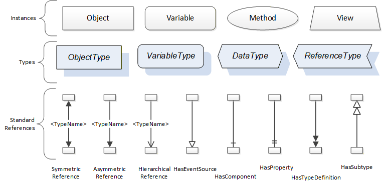
A complete description of the different types of Nodes and References can be found in OPC 10000-3 and the base structure is described in OPC 10000-5.
OPC UA specification defines a very wide range of functionality in its basic information model. It is not expected that all Clients or Servers support all functionality in the OPC UA specifications. OPC UA includes the concept of Profiles, which segment the functionality into testable certifiable units. This allows the definition of functional subsets (that are expected to be implemented) within a companion specification. The Profiles do not restrict functionality, but generate requirements for a minimum set of functionalities (see OPC 10000-7)
4.2.3.2 Namespaces
OPC UA allows information from many different sources to be combined into a single coherent AddressSpace. Namespaces are used to make this possible by eliminating naming and id conflicts between information from different sources. Namespaces in OPC UA have a globally unique string called a NamespaceUri and a locally unique integer called a NamespaceIndex. The NamespaceIndex is only unique within the context of a Session between an OPC UA Client and an OPC UA Server. The Services defined for OPC UA use the NamespaceIndex to specify the Namespace for qualified values.
There are two types of values in OPC UA that are qualified with Namespaces: NodeIds and QualifiedNames. NodeIds are globally unique identifiers for Nodes. This means the same Node with the same NodeId can appear in many Servers. This, in turn, means Clients can have built in knowledge of some Nodes. OPC UA Information Models generally define globally unique NodeIds for the TypeDefinitions defined by the Information Model.
QualifiedNames are non-localized names qualified with a Namespace. They are used for the BrowseNames of Nodes and allow the same names to be used by different information models without conflict. TypeDefinitions are not allowed to have children with duplicate BrowseNames; however, instances do not have that restriction.
4.2.3.3 Companion Specifications
An OPC UA companion specification for an industry specific vertical market describes an Information Model by defining ObjectTypes, VariableTypes, DataTypes and ReferenceTypes that represent the concepts used in the vertical market, and potentially also well-defined Objects as entry points into the AddressSpace.
4.2.3.4 Introduction to OPC UA Devices
The OPC 10000-100 specification is an extension of the overall OPC Unified Architecture specification series and defines the information model associated with Devices. The model is intended to provide a unified view of Devices irrespective of the underlying Device protocols. Controllers are physical or logical Devices and the Devices model is therefore used as base for the IEC 61131-3 information model.
The Devices information model specifies different ObjectTypes and procedures used to represent Devices and related components like the communication infrastructure in an OPC UA Address Space. The main use cases are Device configuration and diagnostic, but it allows a general and standardized way for any kind of application to access Device related information. The following examples illustrate the concepts used in this specification. See OPC 10000-100 for the complete definition of the Devices information model.
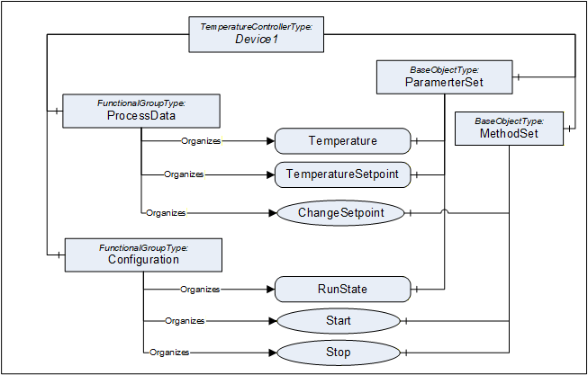
Figure 7 shows an example for a temperature controller represented as Device Object. The component ParameterSet contains all Variables describing the Device. The component MethodSet contains all Methods provided by the Device. Both components are inherited from the TopologyElementType which is the root Object type of the Device Object type hierarchy. Objects of the type FunctionalGroupType are used to group the Parameters and Methods of the Device into logical groups. The FunctionalGroupType and the grouping concept are defined in OPC 10000-100 but the groups are Device type specific i.e. the groups ProcessData and Configuration are defined by the TemperatureControllerType in this example.
Another OPC 10000-100 concept used in this specification is described in Figure 8. The ConfigurableObjectType is used to provide a way to group subcomponents of a Device and to indicate which types of subcomponents can be instantiated. The allowed types are referenced from the SupportedTypes folder. This information can be used by configuration clients to allow a user to select the type to instantiate as subcomponent of the Device.
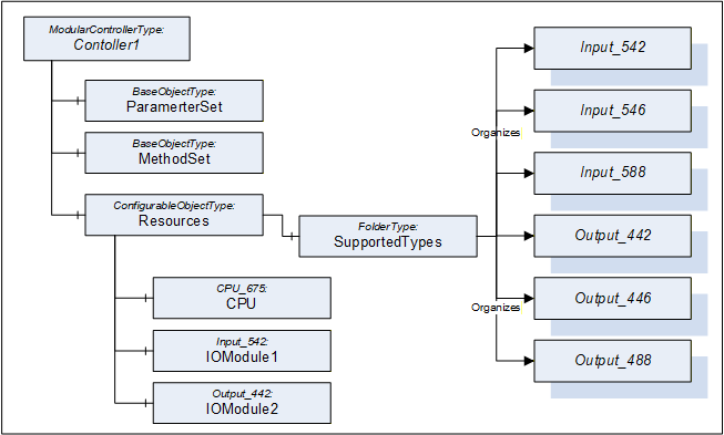
The SupportedTypes Folder can contain different subsets of ObjectTypes for different instances of the ModularControlerType depending on their current configuration since the list contains only types that can be instantiated for the current configuration. The example expects that only one CPU can be used in the ModularControlerType and this CPU is already configured. The SupportedTypes Folder on the ModularControlerType contains all possible types including CPU types that can be used in the ModularControlerType.
4.3 Introductory Example
A simple example shall be used to explain how the above introduced OPC UA concepts are used to represent IEC 61131-3 elements in an OPC UA Server.
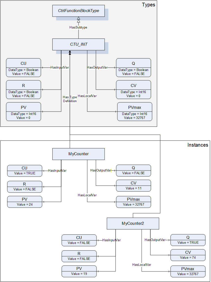
According to IEC 61131-3IEC 61131-3, Ctrl Function Blocks consist of a name, Ctrl Variables with associated data types (input, output, internal), and a body containing the algorithm to be executed. These data are represented by OPC UA ObjectTypes derived from the ObjectType CtrlFunctionBlockType (see Figure 11).
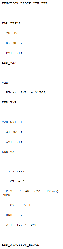
To start, IEC 61131-3IEC 61131-3 requires a Ctrl Function Block type declaration. Here an integer up-counter is used which follows the IEC 61131-3 standard counter Ctrl Function Block. CTU_INT contains three input Ctrl Variables (CU - counter up, R - reset, PV - primary value), one local Ctrl Variable (PVmax) and two output Ctrl Variables (Q, CV - counter value) with their respective data types. Furthermore, CTU_INT has a body containing the algorithm to do the actual counting. The formal declaration of CTU_INT using the Structured Text programming language is shown in Figure 9.
The OPC UA representation of CTU_INT is shown in Figure 11. The ObjectType CTU_INT is a subtype of the ObjectType CtrlFunctionBlockType. Its components are defined by instance declaration and referenced by HasInputVar, HasLocalVar, and HasOutputVar References.
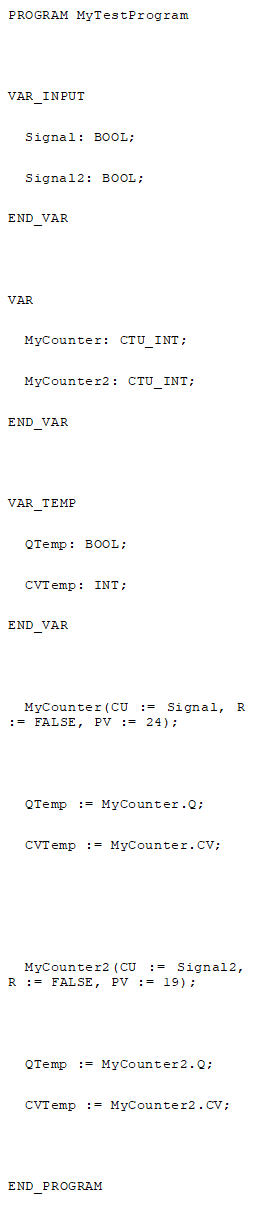
After declaration of CTU_INT it is instantiated twice (MyCounter, MyCounter2) and used within a Ctrl Program MyTestProgram shown in Figure 10. Signal and Signal 2 are counted, the Ctrl Function Block output Ctrl Variables are transferred to some temporary Ctrl Variables but are not further processed in this example.
The OPC UA representation of the Objects MyCounter and MyCounter2 is shown in Figure 11. The Objects are instances of the ObjectType CTU_INT which is indicated by the HasTypeDefinition References. The example specific ObjectType CTU_INT is derived from the ObjectType CtrlFunctionBlockType which is indicated by the HasSubType Reference. Current values at a certain point in time are provided by the instances, e. g. the current counter value of MyCounter equals 11. The Ctrl Program MyTestProgram is not represented in the figure.