This filter system has two identical filter units and two fans. Only one filter unit is in operation at a time. Both units have a common air inflow and outflow. The air flow can be routed through either of the filter units via switch-over flaps.
In this example, the ducting of the common air intake and outlet of the filter units is represented by the two air connections on the filter system. The total airflow is distributed to the two filter units via the switch flaps. The split airflow is represented by the two air connections on the filter units.
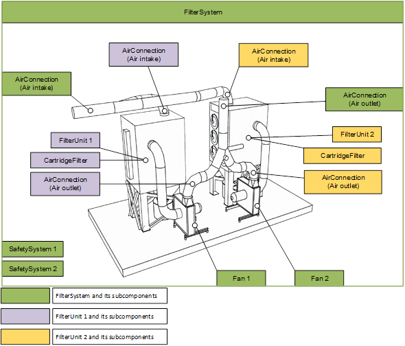
Figure 7 – Components installed in the air filtration system of example 1
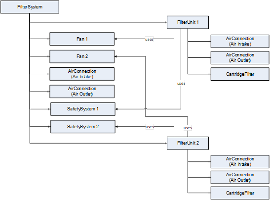
Figure 8 – Formal representation of example 1
This filter system is used for the filtration of laser dust. It is modelled as a filter system with one filter unit. Physically, three different filter types are installed: a cartridge filter (CartridgeFilter1), a HEPA storage filter (CartridgeFilter2), and a sorption filter (CartridgeFilter3). In the PAEFS data model, all three filters are represented by the cartridge filter type. Assigned to CartridgeFilter1 are a device for adding filter aids to bind sticky and very fine laser smoke, and a cleaning unit for removing dust from the cartridge filter.
The assignment in the PAEFS data model is done via the Uses reference. The system also has several safety systems that are connected to the component to be monitored via a Uses reference.
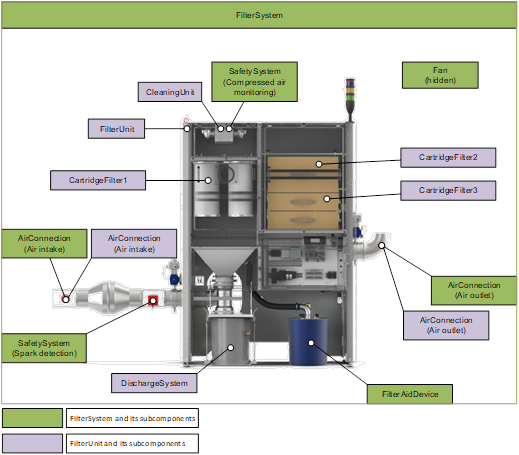
Figure 9 – Components installed in the air filtration system of example 2
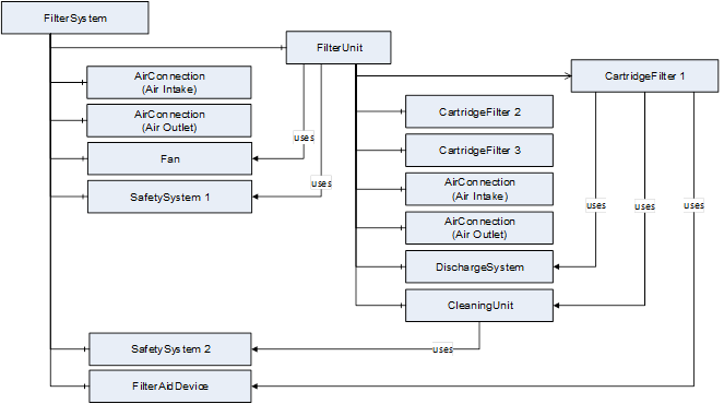
Figure 10 – Formal representation of example 2
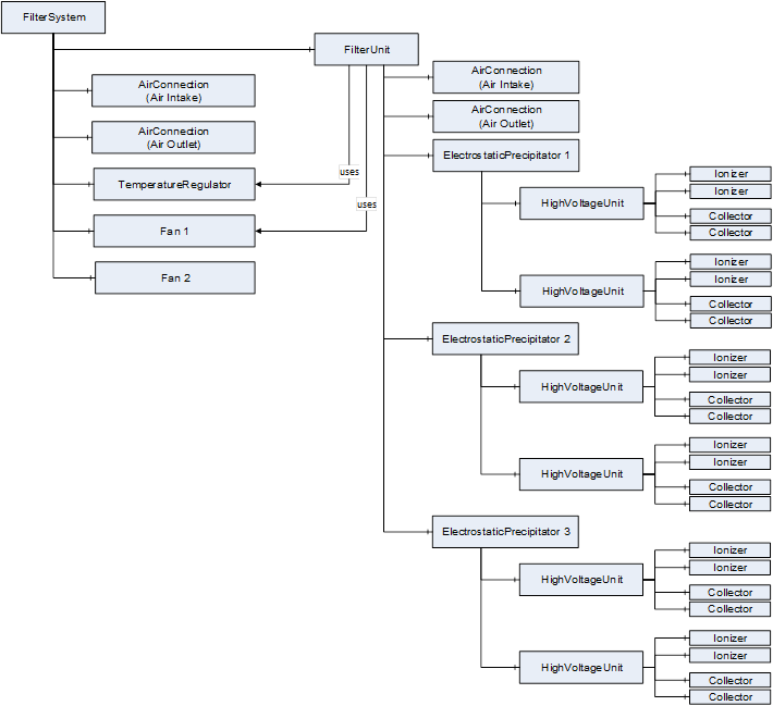
This filter system is used for the filtration of plasticizers using electrostatic precipitators. The polluted intake air is drawn in by a fan (Fan 1). The polluted air is mixed with fresh air before it is directed to the precipitator. The fresh air is preheated by a heat exchanger and a heater (temperature regulator). A second fan (Fan 2) is used for this purpose. The actual separation is performed by three electrostatic precipitators, each with two high-voltage units. Each high-voltage unit has two collectors and two ionizers. Each electrostatic precipitator is considered as one stage of the filter unit.
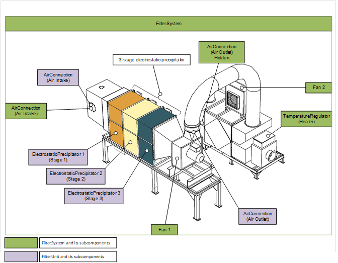
Figure 11 – Components installed in the air filtration system of example 3