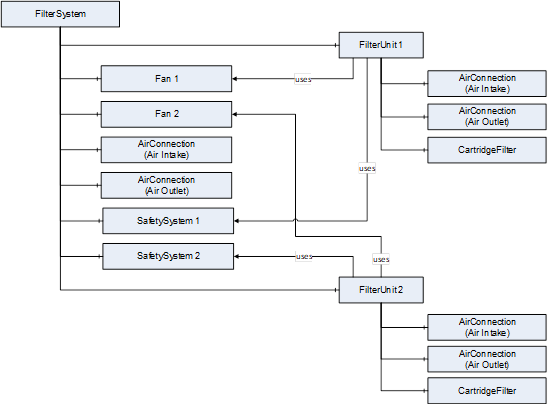
This filter system has two identical filter units and two fans. Only one filter unit is in operation at a time. Both units have a common air inflow and outflow. The air flow can be routed through either of the filter units via switch-over flaps.
In this example, the ducting of the common air intake and outlet of the filter units is represented by the two air connections on the filter system. The total airflow is distributed to the two filter units via the switch flaps. The split airflow is represented by the two air connections on the filter units.
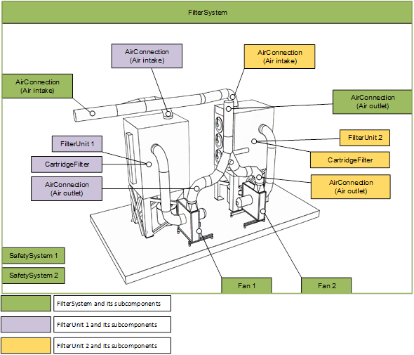
Figure 7 – Components installed in the air filtration system of example 1