A metal forming machine is described by an instance of the 8:MachineToolType defined in OPC 40501-1 Machine Tools and has various extensions for the metal forming specific values and process data. The 8:MachineToolType Instance can be extended by the following points through metal forming specific objects types (see Figure 10). The object type 8:ElementMonitoringType from the 0:BaseObjectType instance is extended by the Metal Forming ObjectTypes ProcessWorkingUnitType (7.4) and FormingProcessWorkingUnitType (7.5). The ObjectType 8:BaseToolType is supplemented by the ObjectTypes FormingToolType (7.6) and FormingMultiToolType (7.7). The example in Figure 9 also shows an extension of the 8:MachineToolType. To identify machines of different manufacturers, the information in the 2:Identification component of the 8:MachineToolType can be used.
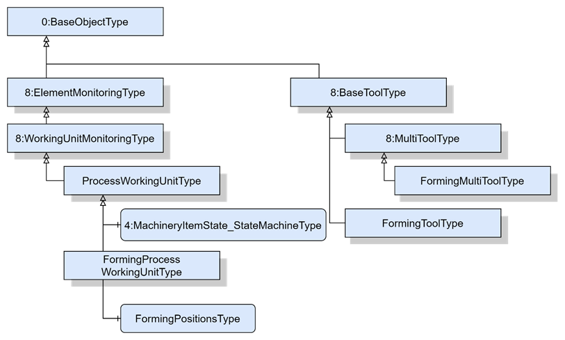
Figure 10 – Extension of the MachineTool
The CyclicProcessValueType (see Figure 11) is a subtype of the 7:ProcessValueType and is used if the monitoring of dependent on repetitive processes inside a run is done. Therefore, it is important to remind the differences between a job order, run and cycle defined in the Metal Forming terms 3.2. The CyclicProcessValueType describes a machining cycle of a forming process.
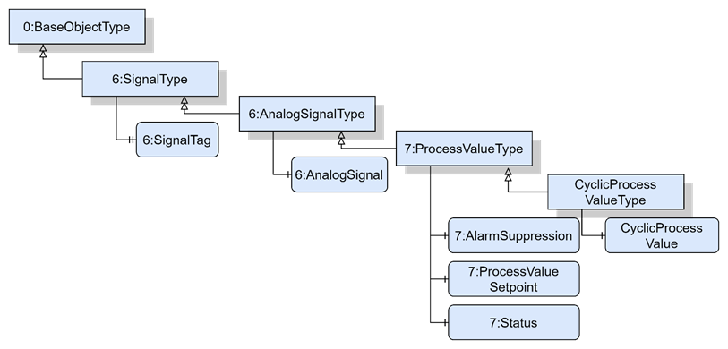
Figure 11 – CyclicProcessValueType
The CylicProcessValueType is formally defined in Table 15.
Table 15 – CyclicProcessValueType Definition
|
Attribute |
Value |
||||
|
BrowseName |
CyclicProcessValueType |
||||
|
IsAbstract |
False |
||||
|
References |
Node Class |
BrowseName |
DataType |
TypeDefinition |
Other |
|
Subtype of the 7:ProcessValueType defined in OPC 40001-2 i.e. inheriting the InstanceDeclarations of that Node. |
|||||
|
0:HasComponent |
Variable |
CyclicProcessValue |
CyclicProcessValueData Type |
CyclicProcessValue VariableType |
M |
|
Conformance Units |
|||||
|
MetalForming CyclicProcessValueType |
|||||
CyclicProcessValue describes the transactional context between the 6:AnalogSignal, 7:ProcessValueSetpoint and the CycleCount. The DataType CyclicProcessValueDataType is defined in 10.1. The corresponding TypeDefinition CyclicProcessValueVariableType is defined in 9.1.
The FormingPositionsType (see Figure 12) defines characteristic positions of a forming process and is formally defined in Table 16. For each cycle, the selected positions will get the ActualValue, Setpoint, EURange, EngineeringUnits and corresponding CycleCount as a CyclicProcessValueType, defined in 7.2. Figure 13 shows a hydraulic press machine with a cushion, indicating the positions of the characteristic points of a forming process.
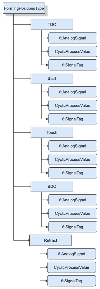
Figure 12 – FormingPositionsType
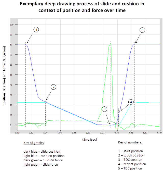
Figure 13 – Example of a characteristic forming diagram of a hydraulic press
Table 16 – FormingPositionsType definition
|
Attribute |
Value |
||||
|
BrowseName |
FormingPositionsType |
||||
|
IsAbstract |
False |
||||
|
References |
Node Class |
BrowseName |
DataType |
TypeDefinition |
Other |
|
Subtype of the 0:BaseObjectType defined in OPC 10000-5 i.e. inheriting the InstanceDeclarations of that Node. |
|||||
|
0:HasComponent |
Object |
TDC |
|
CyclicProcessValueType |
O |
|
0:HasComponent |
Object |
Start |
|
CyclicProcessValueType |
O |
|
0:HasComponent |
Object |
Touch |
|
CyclicProcessValueType |
O |
|
0:HasComponent |
Object |
BDC |
|
CyclicProcessValueType |
O |
|
0:HasComponent |
Object |
Retract |
|
CyclicProcessValueType |
O |
|
Conformance Units |
|||||
|
MetalForming FormingPositionsType |
|||||
TDC is defined in the Metal Forming terms 3.2.1.
Start defines the starting point of a forming process, which can be different to TDC.
Touch defines the position where the workpiece and tool have their first contact.
BDC is defined in the Metal Forming terms 3.2.1.
Retract defines the position where workpiece and tool separate from each other.
The ProcessWorkingUnitType (see Figure 14) provides an instance of a unit which is part of the forming and / or production process and is formally defined in Table 17.
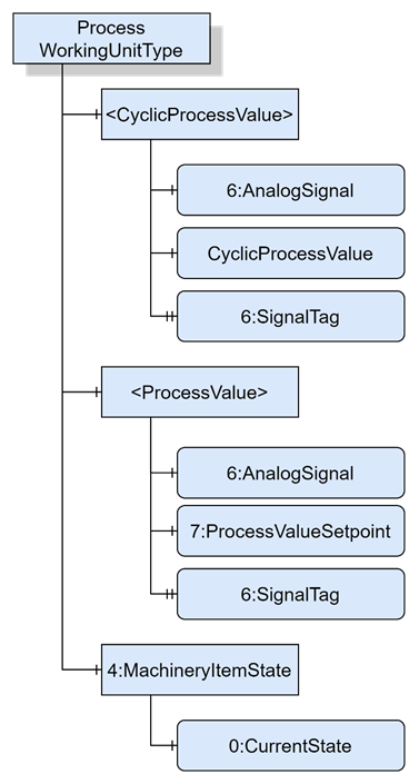
Figure 14 – ProcessWorkingUnitType
Table 17 – ProcessWorkingUnitType Definition
|
Attribute |
Value |
||||
|
BrowseName |
ProcessWorkingUnitType |
||||
|
IsAbstract |
False |
||||
|
References |
Node Class |
BrowseName |
DataType |
TypeDefinition |
Other |
|
Subtype of the 8:WorkingUnitMonitoringType defined in REF OPC40501_1 \h OPC 40501-1 Machine Tools |
|||||
|
0:HasComponent |
Object |
<ProcessValue> |
|
7:ProcessValueType |
OP |
|
0:HasComponent |
Object |
<CyclicProcessValue> |
|
CyclicProcessValue Type |
OP |
|
0:HasComponent |
Object |
4:MachineryItemState |
|
4:MachineryItemState_ StateMachineType |
M |
|
Conformance Units |
|||||
|
MetalForming ProcessWorkingUnitType |
|||||
<ProcessValue> describes the monitoring of a signal from the corresponding working unit. Since there are more than one monitoring signals available per working unit, the 7:ProcessValue is defined as an optional placeholder. The 7:ProcessValueType is defined in OPC 40001-2.
<CyclicProcessValue> is of type CyclicProcessValueType, which is a subtype of 7:ProcessValueType and is representing process values and a transactional context between the 6:AnalogSignal, 7:ProcessValueSetpoint and the actual cycle count of the last cycle. The CyclicProcessValueType is formally defined in 7.2.
4:MachineryItemState represents the current state of the working unit.
The FormingProcessWorkingUnitType (see Figure 15) represents a forming related working unit process, which needs to describe the actual forming position(s) of the last cycle, next to the processing parameters defined by the ProcessWorkingUnitType in Table 17. Therefore, FormingProcessWorkingUnitType is a subtype of ProcessWorkingUnitType and is formally defined in Table 18.
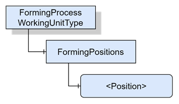
Figure 15 – FormingProcessWorkingUnitType
Table 18 – FormingProcessWorkingUnitType Definition
|
Attribute |
Value |
||||
|
BrowseName |
FormingProcessWorkingUnitType |
||||
|
IsAbstract |
False |
||||
|
References |
Node Class |
BrowseName |
DataType |
TypeDefinition |
Other |
|
Subtype of the ProcessWorkingUnitType defined in Table 17. |
|||||
|
0:HasComponent |
Object |
FormingPositions |
|
FormingPositionsType |
M |
|
Conformance Units |
|||||
|
MetalForming FormingProcessWorkingUnitType |
|||||
FormingPositions is representing an ObjectType, including a definition of optional positions which are most used in forming processes. The TypeDefintion for the FormingPositionsType is done in 7.3.
The FormingToolType (see Figure 16) is a subtype of the 8:BaseToolType and provides metal forming specific tool parameter in the Location Object. Therefore, the Location Object is overridden and adjusted with metal forming specific tool parameters. The FormingToolType is defined in Table 19.
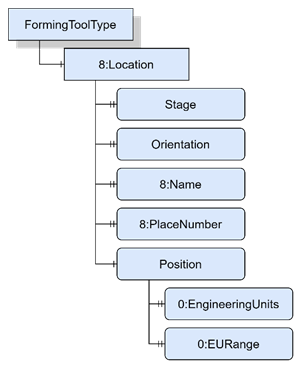
Table 19 – FormingToolType Definition
|
Attribute |
Value |
||||
|
BrowseName |
FormingToolType |
||||
|
IsAbstract |
False |
||||
|
References |
Node Class |
BrowseName |
DataType |
TypeDefinition |
Other |
|
Subtype of the 8:BaseToolType defined in REF OPC40501_1 \h OPC 40501-1 Machine Tools. |
|||||
|
0:HasComponent |
Object |
8:Location |
|
0:BaseObjectType |
O |
|
Conformance Units |
|||||
|
MetalForming FormingToolType |
|||||
The components of the FormingToolType have additional subcomponents which are defined in Table 20.
Table 20 – FormingToolType Additional Subcomponents
|
Source Path |
Reference |
NodeClass |
BrowseName |
DataType |
TypeDefinition |
Others |
|
8:Location |
0:HasProperty |
Variable |
Orientation |
String |
0:PropertyType |
O |
|
8:Location |
0:HasComponent |
Variable |
Position |
Double |
0:AnalogUnitRangeType |
O |
|
8:Location |
0:HasProperty |
Variable |
Stage |
UInt16 |
0:PropertyType |
O |
|
8:Location |
0:HasProperty |
Variable |
8:Name |
String |
0:PropertyType |
M |
|
8:Location |
0:HasProperty |
Variable |
8:PlaceNumber |
UInt16 |
0:PropertyType |
M |
The 8:Location parameter, formally defined in OPC 40501-1 UA for MachineTool, indicates, where the tool is located.
Orientation indicates the mounted direction of the tool if there are several possibilities (e.g. “Front” or “Back” at bending machines) to align the tool at the tool holder.
Position is a parameter which describes the absolute position of the central tool axis in dependency to the central middle axis of the complete tool holder. This is necessary if the machine consists of several stages or if the is mounted asymmetric in dependency to the central middle axis of the complete tool holder.
The Position parameter is extended by an 0:EngineeringUnits property as well as an 0:EURange property describing detailed static information.
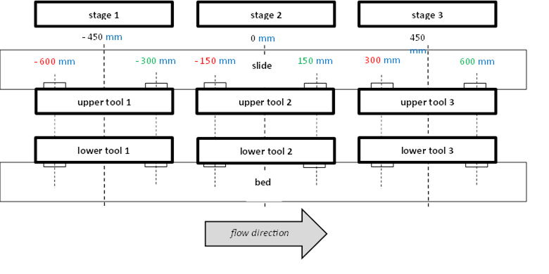
Figure 17 – Position parameter: Part 1
describes a hydraulic press machine with three stages, the absolute Positions as well as the corresponding unit (mm) and the low (red) and high (green) limits of each tool in the current stage.
The Stage parameter indicates on which stage the current defined tool is located.
The 8:PlaceNumber and the 8:Name are used like in the 8:BaseToolType.
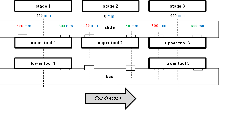
Figure 18 – Position parameter: Part 2
The FormingMultiToolType (see Figure 19) provides an optional placeholder for FormingToolTypes and is formally defined in Table 21.
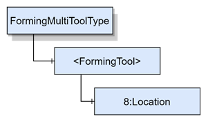
Figure 19 – FormingMultiToolType
Table 21 – FormingMultiToolType Definition
|
Attribute |
Value |
||||
|
BrowseName |
FormingMultiToolType |
||||
|
IsAbstract |
False |
||||
|
References |
Node Class |
BrowseName |
DataType |
TypeDefinition |
Other |
|
Subtype of the 8:MultiToolType defined in REF OPC40501_1 \h OPC 40501-1 Machine Tools. |
|||||
|
0:HasComponent |
Object |
<FormingTool> |
|
FormingToolType |
OP |
|
Conformance Units |
|||||
|
MetalForming FormingMultiToolType |
|||||
The optional placeholder <FormingTool > Object contains information about the individual forming tools within the multitool.
The supertype FormingProcessConditionClassType (see Figure 20) is a subtype of the ProcessConditionClassType and describes condition which can appear during the forming process, formally defined in Table 22.
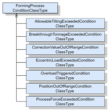
Figure 20 – FormingProcessConditionClassType
Table 22 – FormingProcessConditionClassType Definition
|
Attribute |
Value |
||||
|
BrowseName |
FormingProcessConditionClassType |
||||
|
IsAbstract |
True |
||||
|
References |
Node Class |
BrowseName |
DataType |
TypeDefinition |
Other |
|
Subtype of the ProcessConditionClassType defined in REF UAPart9 \h OPC 10000-9 Specification. |
|||||
|
Conformance Units |
|||||
|
MetalForming FormingProcessConditionClassType |
|||||
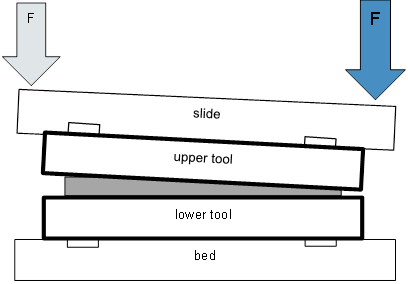
The AllowableTiltingExceededConditionClassType is an abstract ObjectType which should be caused when the allowable tilting of the machine limits is exceeded. The tilt is related to the punch of the hydraulic press machine as shown in Figure 21.
The AllowableTiltingExceededConditionClassType is formally defined in Table 23.
Table 23 – AllowableTiltingExceededConditionClassType Definition
|
Attribute |
Value |
||||
|
BrowseName |
AllowableTiltingExceededConditionClassType |
||||
|
IsAbstract |
True |
||||
|
References |
Node Class |
BrowseName |
DataType |
TypeDefinition |
Other |
|
Subtype of the FormingProcessConditionClassType defined in 7.8 i.e. inheriting the InstanceDeclarations of that Node. |
|||||
|
Conformance Units |
|||||
|
MetalForming AllowableTiltingExceededConditionClassType |
|||||
The BreakthroughTonnageExceededConditionClassType is an abstract ObjectType which should be caused when the breakthrough tonnage limit of the machine is exceeded. The breakthrough tonnage generates a resistance by internal orifices that restrict the flow of oil out of the cylinder resulting in a cushioning effect. For example, shock dampers provide an upward counterpressure at the moment of breakthrough, resulting in a damping force as shown in Figure 22 for a hydraulic press machine.
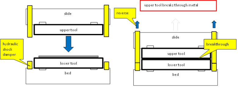
Figure 22 – Breakthrough tonnage
The BreakthroughTonnageExceededConditionClassType is formally defined in Table 24.
Table 24 – BreakthroughTonnageExceededConditionClassType Definition
|
Attribute |
Value |
||||
|
BrowseName |
BreakthroughTonnageExceededConditionClassType |
||||
|
IsAbstract |
True |
||||
|
References |
Node Class |
BrowseName |
DataType |
TypeDefinition |
Other |
|
Subtype of the FormingProcessConditionClassType defined in 7.8 i.e. inheriting the InstanceDeclarations of that Node. |
|||||
|
Conformance Units |
|||||
|
MetalForming BreakthroughTonnageExceededConditionClassType |
|||||
The CorrectionValueOutOfRangeConditionClassType is an abstract ObjectType which should be caused when the correction value of the machine limits is exceeded. In this context, correction values mean dynamically adjusting values during production process, to get a better production quality. EXAMPLE: immersion depth control
The CorrectionValueOutOfRangeConditionClassType is formally defined in Table 25.
Table 25 – CorrectionValueOutOfRangeConditionClassType Definition
|
Attribute |
Value |
||||
|
BrowseName |
CorrectionValueOutOfRangeConditionClassType |
||||
|
IsAbstract |
True |
||||
|
References |
Node Class |
BrowseName |
DataType |
TypeDefinition |
Other |
|
Subtype of the FormingProcessConditionClassType defined in 7.8 i.e. inheriting the InstanceDeclarations of that Node. |
|||||
|
Conformance Units |
|||||
|
MetalForming CorrectionValueOutOfRangeConditionClassType |
|||||
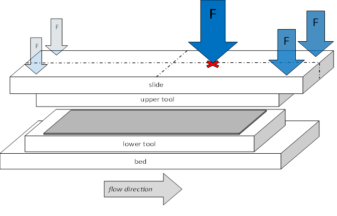
The EccentricLoadExceededConditionClassType is an abstract ObjectType which should be caused when the eccentric load of the machine limits is exceeded. Eccentric load describes the value of the forming force acting off-center as shown in for a hydraulic press machine.
The EccentricLoadExceededConditionClassType is formally defined in Table 26.
Table 26 – EccentricLoadExceededConditionClassType Definition
|
Attribute |
Value |
||||
|
BrowseName |
EccentricLoadExceededConditionClassType |
||||
|
IsAbstract |
True |
||||
|
References |
Node Class |
BrowseName |
DataType |
TypeDefinition |
Other |
|
Subtype of the FormingProcessConditionClassType defined in 7.8 i.e. inheriting the InstanceDeclarations of that Node. |
|||||
|
Conformance Units |
|||||
|
MetalForming EccentricLoadExceededConditionClassType |
|||||
The OverloadTriggeredConditionClassType is an abstract ObjectType which should be caused when the overload of the machine limits is triggered. The overload refers to a situation where the press machine is subjected to a force or load that exceeds its normal operating capacity.
The OverloadTriggeredConditionClassType is formally defined in Table 27.
Table 27 – OverloadTriggeredConditionClassType Definition
|
Attribute |
Value |
||||
|
BrowseName |
OverloadTriggeredConditionClassType |
||||
|
IsAbstract |
True |
||||
|
References |
Node Class |
BrowseName |
DataType |
TypeDefinition |
Other |
|
Subtype of the FormingProcessConditionClassType defined in 7.8 i.e. inheriting the InstanceDeclarations of that Node. |
|||||
|
Conformance Units |
|||||
|
MetalForming OverloadTriggeredConditionClassType |
|||||
The PositionOutOfRangeConditionClassType is an abstract ObjectType which should be caused when the operating range of the machine is exceeded. The position out of range generally refers to a situation where the position of a part or tool is exceeded by the normal operating range of the press machine.
The PositionOutOfRangeConditionClassType is formally defined in Table 28.
Table 28 – PositionOutOfRangeConditionClassType Definition
|
Attribute |
Value |
||||
|
BrowseName |
PositionOutOfRangeConditionClassType |
||||
|
IsAbstract |
True |
||||
|
References |
Node Class |
BrowseName |
DataType |
TypeDefinition |
Other |
|
Subtype of the FormingProcessConditionClassType defined in 7.8 i.e. inheriting the InstanceDeclarations of that Node. |
|||||
|
Conformance Units |
|||||
|
MetalForming PositionOutOfRangeConditionClassType |
|||||
The ProcessForceExceededConditionClassType is an abstract ObjectType which should be caused when the process force of the machine is exceeded. The process force is the force that is applied to the material being formed by the press.
The ProcessForceExceededConditionClassType is formally defined in Table 29.
Table 29 – ProcessForceExceededConditionClassType Definition
|
Attribute |
Value |
||||
|
BrowseName |
ProcessForceExceededConditionClassType |
||||
|
IsAbstract |
True |
||||
|
References |
Node Class |
BrowseName |
DataType |
TypeDefinition |
Other |
|
Subtype of the FormingProcessConditionClassType defined in 7.8 i.e. inheriting the InstanceDeclarations of that Node. |
|||||
|
Conformance Units |
|||||
|
MetalForming ProcessForceExceededConditionClassType |
|||||