The FormingToolType (see Figure 16) is a subtype of the 8:BaseToolType and provides metal forming specific tool parameter in the Location Object. Therefore, the Location Object is overridden and adjusted with metal forming specific tool parameters. The FormingToolType is defined in Table 19.
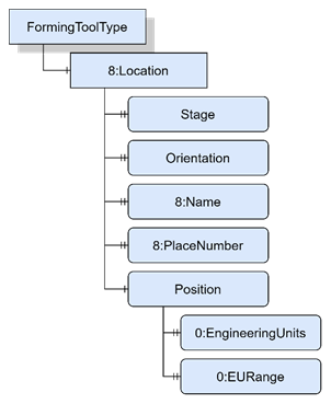
Table 19 – FormingToolType Definition
|
Attribute |
Value |
||||
|
BrowseName |
FormingToolType |
||||
|
IsAbstract |
False |
||||
|
References |
Node Class |
BrowseName |
DataType |
TypeDefinition |
Other |
|
Subtype of the 8:BaseToolType defined in REF OPC40501_1 \h OPC 40501-1 Machine Tools. |
|||||
|
0:HasComponent |
Object |
8:Location |
|
0:BaseObjectType |
O |
|
Conformance Units |
|||||
|
MetalForming FormingToolType |
|||||
The components of the FormingToolType have additional subcomponents which are defined in Table 20.
Table 20 – FormingToolType Additional Subcomponents
|
Source Path |
Reference |
NodeClass |
BrowseName |
DataType |
TypeDefinition |
Others |
|
8:Location |
0:HasProperty |
Variable |
Orientation |
String |
0:PropertyType |
O |
|
8:Location |
0:HasComponent |
Variable |
Position |
Double |
0:AnalogUnitRangeType |
O |
|
8:Location |
0:HasProperty |
Variable |
Stage |
UInt16 |
0:PropertyType |
O |
|
8:Location |
0:HasProperty |
Variable |
8:Name |
String |
0:PropertyType |
M |
|
8:Location |
0:HasProperty |
Variable |
8:PlaceNumber |
UInt16 |
0:PropertyType |
M |
The 8:Location parameter, formally defined in OPC 40501-1 UA for MachineTool, indicates, where the tool is located.
Orientation indicates the mounted direction of the tool if there are several possibilities (e.g. “Front” or “Back” at bending machines) to align the tool at the tool holder.
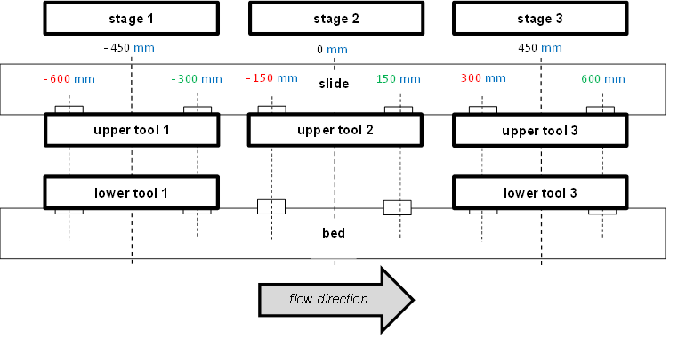
Position is a parameter which describes the absolute position of the central tool axis in dependency to the central middle axis of the complete tool holder. This is necessary if the machine consists of several stages or if the is mounted asymmetric in dependency to the central middle axis of the complete tool holder.
The Position parameter is extended by an 0:EngineeringUnits property as well as an 0:EURange property describing detailed static information.
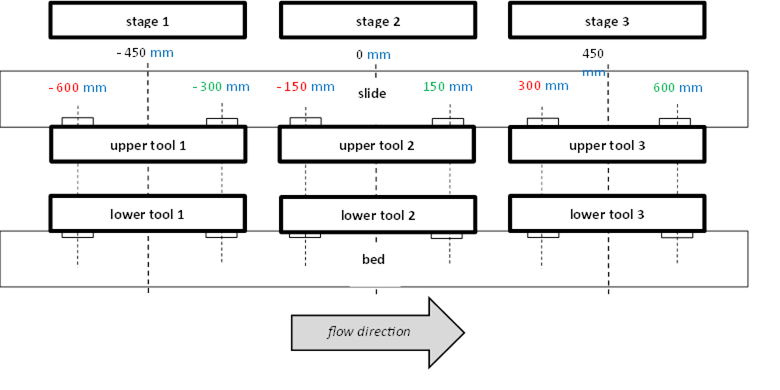
Figure 17 – Position parameter: Part 1
describes a hydraulic press machine with three stages, the absolute Positions as well as the corresponding unit (mm) and the low (red) and high (green) limits of each tool in the current stage.
The Stage parameter indicates on which stage the current defined tool is located.
The 8:PlaceNumber and the 8:Name are used like in the 8:BaseToolType.