6 IO-Link Information Model Overview
6.1 Modelling Concepts
6.1.1 IO-Link Master
The configuration of the IO-Link Master is done by representing the IO-Link Master as Object having several Variables and Methods to view and to change the configuration. The ports of the IO-Link Master are modelled as individual Objects.
6.1.2 IO-Link Port
The configuration of an IO-Link Port is done by representing the IO-Link Port as Object having several Variables and Methods to view and to change the configuration. If the IO-Link Port has a connected or configured IO-Link Device, the device is referenced from the IO-Link Port.
6.1.3 IO-Link Device
The IO-Link Device is represented as Object having several Variables and Methods to view and to change the configuration. There is a generic ObjectType representing the common functionality of an IO-Link Device, and subtypes of it for the IODD extensions describing the type of a specific IO-Link Device in more detail and providing more intuitive configuration options.
6.1.4 IO-Link Events
Events can occur for different reasons. An IO-Link Master can generate vendor-specific Events; an IO-Link Port generates Events when the communication to the device fails, the device gets exchanged, etc.
The IO-Link Device itself provides event information. The IO-Link Master shall observe the event flag provided with each message. In case it is set, the IO-Link Master shall receive the event information via the acyclic communication mechanisms of IO-Link and forward it to the OPC UA Server and the server provides the received events via the OPC UA interface.
Events provided as IO-Link “Error” or “Warning” are mapped to OPC UA Alarms (see OPC 10000-9), events provided as IO-Link “Notification” as OPC UA Events.
Additional to the observation of the event flag there is the possibility to get information about the status of a stateful IO-Link Event (that is mapped to OPC UA Alarms) by using the DiagEntries of PortStatusList as defined in the SMI (see IO-Link Addendum) and the DetailedDeviceStatus (ISDU Index 0x0025).
6.1.5 Block operations: Up- and Download
An IO-Link Device can be configured by writing ISDU parameters. When a parameter of an IO-Link Device is written, the content is checked for consistency. This is useful, because it can happen that certain value combinations of some parameters are not valid configuration options.
When a single parameter is written, its value is checked against the other parameters that were configured before (or had this value by default). If the check fails, an error is returned. This behaviour causes problems if you want to change set of interdependent parameters.
Because of this, IO-Link provides block operations. If a device is set into the download state (via a system command) the device allows to write many parameters to the device without checking for consistency. When the block parameterization is finished (by sending another system command) the consistency of all changed parameters is checked as a whole. If all parameters are consistent, all changes are accepted, else all changes are rejected.
If the block operations are used to read several parameters, the device does not allow parameters to be changed during this time.
The needed IO-Link system commands (see IO-Link Specification) are mapped to OPC UA Methods.
To avoid concurrent access from different OPC UA Clients while the block operation is used by one OPC UA Client, the OPC UA Client should lock the IO-Link Device using the Lock Object defined in OPC 10000-100.
6.1.6 Managing IODDs
IODDs are managed as ObjectTypes in the server. A specific, well-defined Object called IODDManagement having well-defined Methods is used to load new IODDs to the Server (and thereby creating new ObjectTypes) or to delete IODDs from the Server.
6.1.7 Relating IO-Link Devices to IO-Link Ports
Depending on the configuration of an IO-Link Port and whether a physical IO-Link Device is connected to the IO-Link Port, either an Object representing the IO-Link Device is connected to the IO-Link Port or not. The following state machine describes, whether such an Object is there, and what ObjectType is used.
The top-level state machine defines the states “Port not configured as IO-Link” and “Select Device Instance Type”. In the first state the IO-Link Port is configured that no IO-Link Device is used (PortMode is either DEACTIVATED, DI_C/Q or DO_C/Q) and the optional Device Object is not available. In the second state the IO-Link-Port is configured to be an IO-Link Device (PortMode is either IOL_AUTOSTART or IOL_MANUAL) and the substates indicate whether a Device Object exists as well as the used ObjectType. Changes of the PortMode trigger transitions between the states. For the second state, additional transitions are defined that trigger the re-entrance of the state and thus the re-evaluation whether a Device Object exists as well as the used ObjectType. Those transitions include plugging in or off devices, changing the UseIODD Property or changes of IO-Link Port configuration Parameters.
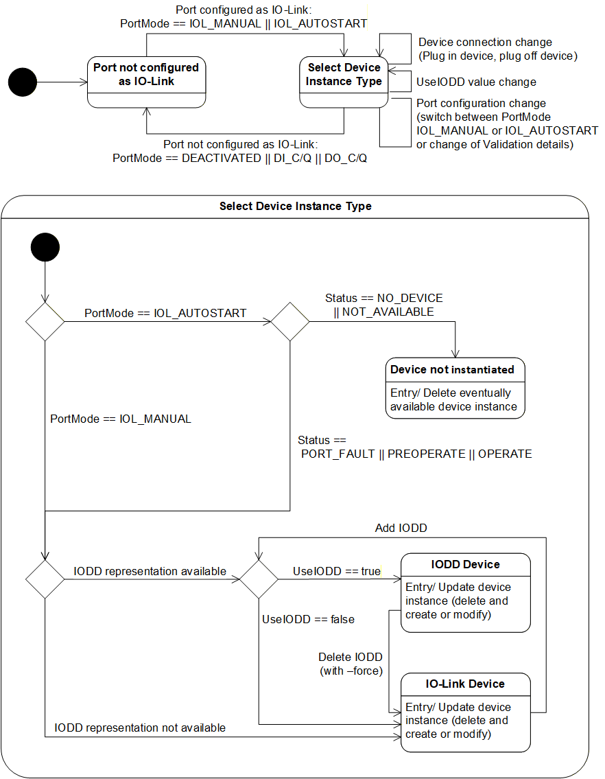
The sub-state-machine of the “Select Device Instance Type” describes three states indicating, whether the Device Object exists and what ObjectType is used.
“Device not instantiated” indicates that the optional Device Object does not exist.
“IODD Device” indicates that the Device Object exists and the IODD is used and therefore the concrete ObjectType related to the IODD is used.
“IO-Link Device” indicates that the Device Object exists and the IOLinkDeviceType is used.
The sub-state-machine defines different choices to find the correct state.
When the PortMode is IOL_AUTOSTART but no device is connected, the “Device not instantiated” state is used.
When the PortMode is IOL_AUTOSTART and a device is connected, or the PortMode is IOL_MANUAL it is further decided if the “IODD Device” or the “IO-Link Device” state is used.
When the IODD representing the IO-Link Device is available in the server and the UseIODD Parameter is “True”, the “IODD Device” state is used, otherwise the “IO-Link Device” state is used.
Note that if an IO-Link Device is connected, the information of the connected IO-Link Device is used to identify the IODD, even if the IO-Link Port has a different device configured (Status = INCORRECT_DEVICE). Only when the PortMode is IOL_MANUAL and no device is connected (Status == NO_DEVICE || NOT_AVAILABLE) the configured device information is used to identify the IODD.
When the IO-Link Port is in the “IODD Device” state and the IODD is deleted (e.g. by the Method RemoveIODD using the force option) it changes to the “IO-Link Device” state.
When the IO-Link Port is in the “IO-Link Device” state and the IODD representing the IO-Link Device is added to the server (e.g. by the Method TransferIODD) and the UseIODD Parameter is “True” it changes to the “IODD Device” state.
Note that there can be limitations on what Variables can be accessed and what Methods can be executed from the Device Object (states “IO-Link Device” or “IODD Device”).
When the PortMode is IOL_MANUAL and no device is connected (Status == NO_DEVICE || NOT_AVAILABLE) the Device Object is available so OPC UA Clients can already be configured to use the configured IO-Link Device, but since no physical IO-Link Device is connected, all access to Variables or Methods requiring device access will fail (bad code). Providing the structure of the configured IO-Link Device is especially helpful if an IODD is used, since the structure defined by the IODD is already available to the OPC UA Client (specific Parameters etc.).
When the PortMode is IOL_MANUAL but the incorrect IO-Link Device is connected (Status == INCORRECT_DEVICE) accessing the Variables representing the process data (e.g. ProcessDataInput, ProcessDataOutput) will fail (bad code).
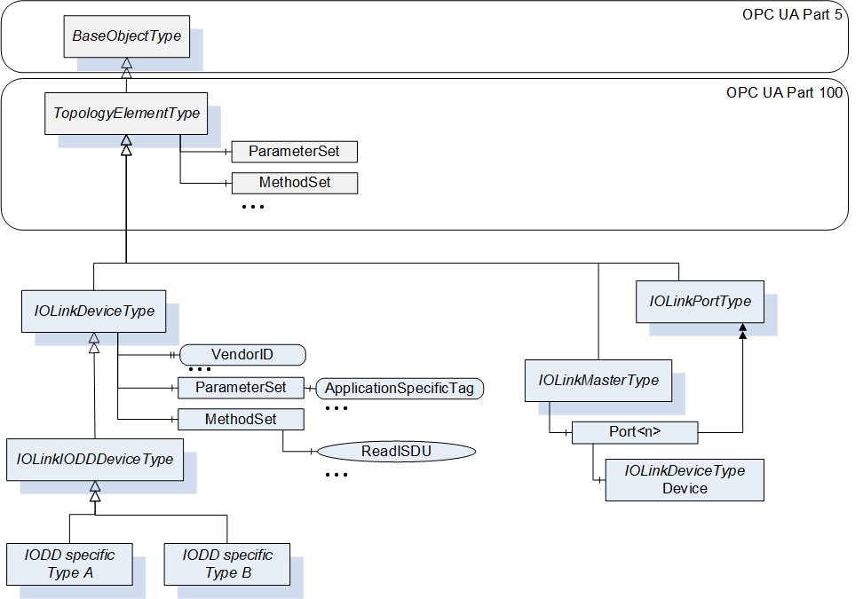
6.2 Model Overview
In Figure 7 an overview of the IO-Link Information Model is given. The IOLinkDeviceType represents IO-Link Devices. In case no IODD is available, this type shall directly be used to represent an IO-Link Device. If an IODD is available, a subtype is used representing the concrete IODD and providing the additional parameters, system commands, etc. defined in the IODD (see section 7.3). The IOLinkDeviceType inherits from TopologyElementType defined in OPC 10000-100 and thus provides basic grouping mechanisms (ParameterSet for parameters and MethodSet for Methods). It also uses basic Properties of a device like SerialNumber defined in OPC 10000-100. Section 7.1 defines details on those Properties and additional Properties like VendorId, Parameters like ApplicationSpecificTag and Methods like ReadISDU. The IO-Link Master is represented by an Object of IOLinkMasterType (see section 7.5). This ObjectType also inherits from the TopologyElementType and defines basic Properties, Parameters and Methods. For each port the IO-Link Master contains an Object of type IOLinkPortType (see section 7.6). The IOLinkPortType inherits from the TopologyElementType and thereby uses the same grouping mechanisms for Parameters and Variables. It defines Properties, Parameters and Methods for the IO-Link Port. If the port has an IO-Link Device connected, the IO-Link Device (Object of type IOLinkDeviceType) is connected to the port.
Instances of IOLinkDeviceType generate Events of type IOLinkDeviceEventType (see section 9.3) and IOLinkDeviceAlarmType (see section 9.8). An OPC UA Server might provide instances of the IOLinkDeviceAlarmType or its subtypes as Objects under the Alarms Object (see Figure 8).
Instances of IOLinkMasterType generate Events of type IOLinkMasterEventType (see section 9.6) and IOLinkMasterAlarmType (see section 9.11). Ports generate events of type IOLinkPortEventType (see section 9.5) and IOLinkPortAlarmType (see section 9.10). Both can provide instances of the IOLinkMasterAlarmType respectively IOLinkPortAlarmType under the Alarms Object (see Figure 8).
In the ObjectType hierarchy the mentioned events are grouped under the IOLinkEventType and the alarms under the IOLinkAlarmType (see Figure 8).
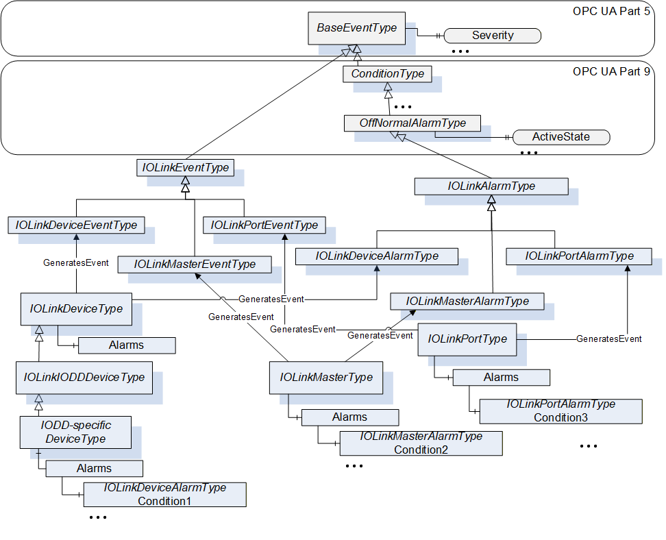
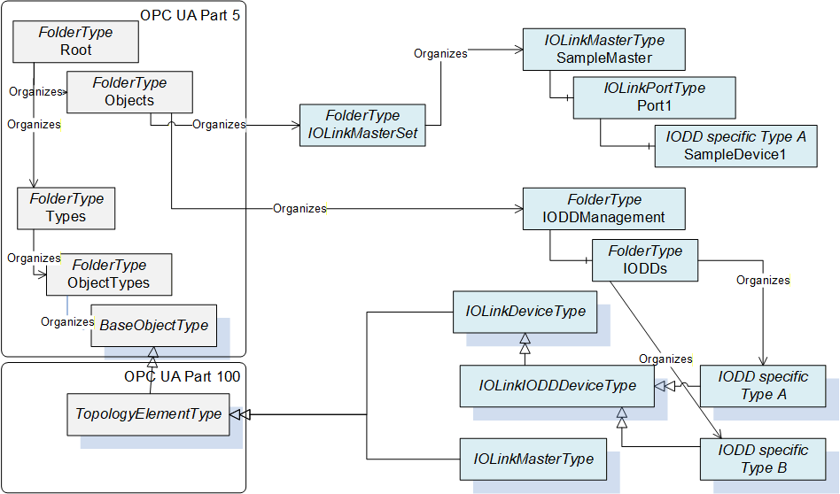
Figure 9 shows the entry points into the AddressSpace. The IOLinkMasterSet provides direct access to the Objects representing IO-Link Masters and indirectly to the Objects representing the IO-Link Devices connected to the Master. The IODDManagement Object contains the Object named IODDs pointing to all ObjectTypes representing an IODD.
Note: In order to figure out how many IO-Link Masters an OPC UA Server currently manages, an OPC UA Client can browse the IOLinkMasterSet and count all Objects of IOLinkMasterType or a subtype of it.
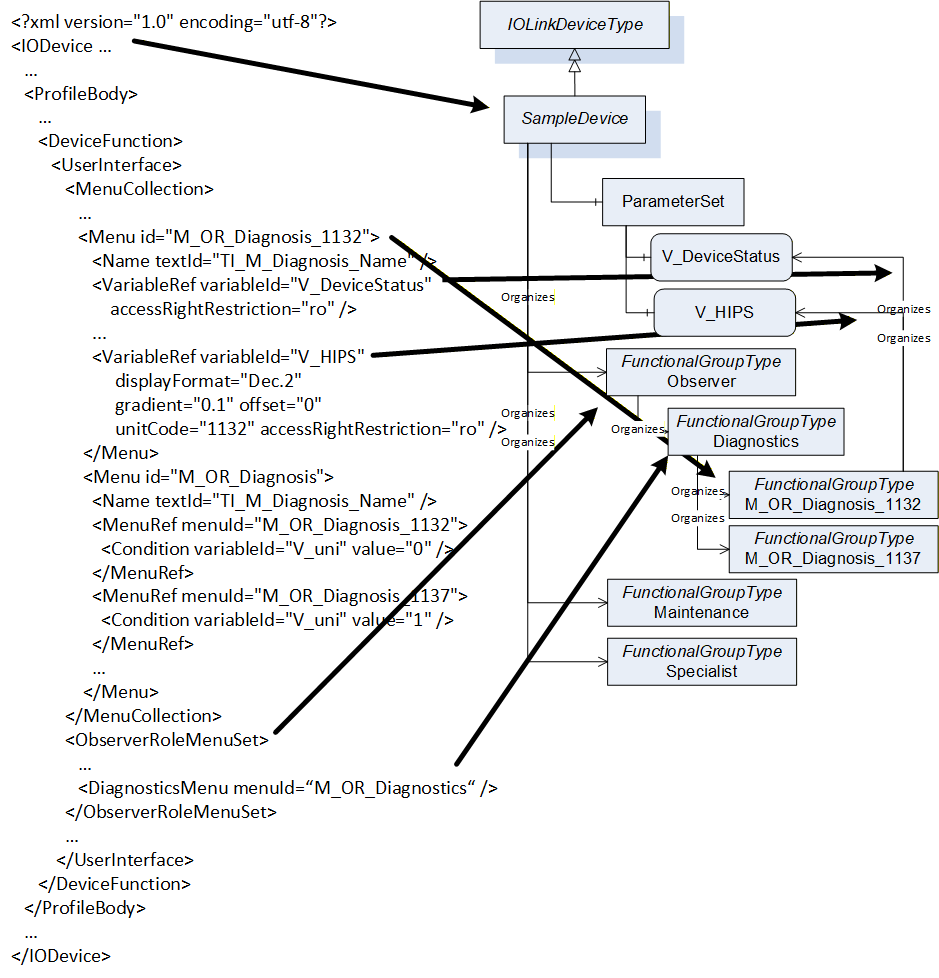
6.3 Mapping IODD information to OPC UA ObjectTypes
This section gives a rough overview on how IODD information is mapped to an OPC UA ObjectType. The formal definition is given in section 7.3.
An IODD consists of an IODevice containing meta data like DocumentInfo and ProfileHeader describing an IO-Link Device. In addition, it contains information about data types (DatatypeCollection), variables accessed acyclic (VariableCollection), process data (ProcessDataCollection), errors (ErrorTypeCollection), events (EventCollection) and menus to group information in user interfaces (UserInterface).
The user interface information consists of entry points for three different user roles (Observer, Maintenance, and Specialist), each one containing an identification menu and optionally parameter, observation, and diagnostics menus. Those menus can reference other menus or variables. Optionally, the user interface information also provides information how to display the process data directly (ProcessDataRefCollection).
The three entry points for the user roles are mapped to OPC UA FunctionalGroups. Each menu that is referenced directly or indirectly as part of such an entry point is also mapped as FunctionalGroup, referenced from its parent FunctionalGroup.
In Figure 10, an example of such a mapping is given. On the left hand, parts of an IODD are shown. On the right, the representation as ObjectType in OPC UA is shown. The IODevice is mapped to an ObjectType. The UserInterface information is mapped mainly to Objects of FunctionalGroupType. The Observer Object is directly connected to the ObjectType, its submenu Diagnostics is referenced by the Observer Object. The Diagnostics menu contains two conditional menus in the IODD, which are both mapped as optional Objects under the Diagnostics Object. The M_OR_Diagnosis_1132 menu references two Variables. This is mapped by referencing the corresponding variables of the ParameterSet. Some details of the mapping like handling conditions or additional information for Variables like EngineeringUnits are not shown in the figure and defined in section 7.3.