The JoiningSystemIdentificationType provides the identification parameters of the joining system and is formally defined in Table 20.
Table 20 – JoiningSystemIdentificationType Definition
|
Attribute |
Value |
||||
|
BrowseName |
JoiningSystemIdentificationType |
||||
|
IsAbstract |
False |
||||
|
References |
Node Class |
BrowseName |
DataType |
TypeDefinition |
Other |
|
Subtype of the 2:FunctionalGroupType defined in OPC 10000-100, i.e., inheriting the InstanceDeclarations of that Node. |
|||||
|
0:HasProperty |
Variable |
0:DefaultInstanceBrowseName |
0:QualifiedName |
0:PropertyType |
|
|
0:HasProperty |
Variable |
2:ProductInstanceUri |
0:String |
0:PropertyType |
O |
|
0:HasProperty |
Variable |
Name |
0:String |
0:PropertyType |
M |
|
0:HasProperty |
Variable |
IntegratorName |
0:String |
0:PropertyType |
O |
|
0:HasProperty |
Variable |
Description |
0:LocalizedText |
0:PropertyType |
O |
|
0:HasProperty |
Variable |
JoiningTechnology |
0:LocalizedText |
0:PropertyType |
O |
|
0:HasProperty |
Variable |
2:Manufacturer |
0:LocalizedText |
0:PropertyType |
O |
|
0:HasProperty |
Variable |
2:ManufacturerUri |
0:String |
0:PropertyType |
O |
|
0:HasProperty |
Variable |
2:Model |
0:LocalizedText |
0:PropertyType |
O |
|
0:HasProperty |
Variable |
SystemId |
0:String |
0:PropertyType |
O |
|
0:HasProperty |
Variable |
4:Location |
0:String |
0:PropertyType |
O |
|
Conformance Units |
|||||
|
IJT Joining System Base |
|||||
|
|
|||||
The component Variables of the JoiningSystemIdentificationType have additional Attributes defined in Table 21.
Table 21 – JoiningSystemIdentificationType Attribute values for child nodes
|
BrowsePath |
Value Attribute |
Description Attribute |
|
0:DefaultInstanceBrowseName |
2:Identification |
The default BrowseName for instances of the type. |
2: ProductInstanceUri is a globally unique resource identifier provided by the manufacturer.
Name is the name of the joining system. It can also be the standard browse name of the instance of JoiningSystemType.
IntegratorName is the name of the system integrator.
Description is the description of the system which could be written by the customer to identify the system. It could be the purpose of the system in the assembly line.
Note: Although there is a description attribute at the node level in OPC UA, Description property was added at the same level as the 2:Identification node for consistency.
JoiningTechnology is a human readable text to identify the joining technology of the joining system.
2:Manufacturer provides a human-readable, localized name of the joining system manufacturer.
2:ManufacturerUri provides a unique identifier for this company. This identifier should be a fully qualified domain name; however, it may be a GUID or similar construct that ensures global uniqueness.
2:Model provides the type of the joining system. Examples: Fixtured System, Handheld System, etc.
SystemId is the system integrator specific identifier for the system. It represents a reference to the manufacturer ERP system.
4:Location is the location of the given system in the given plant or factory in text format.
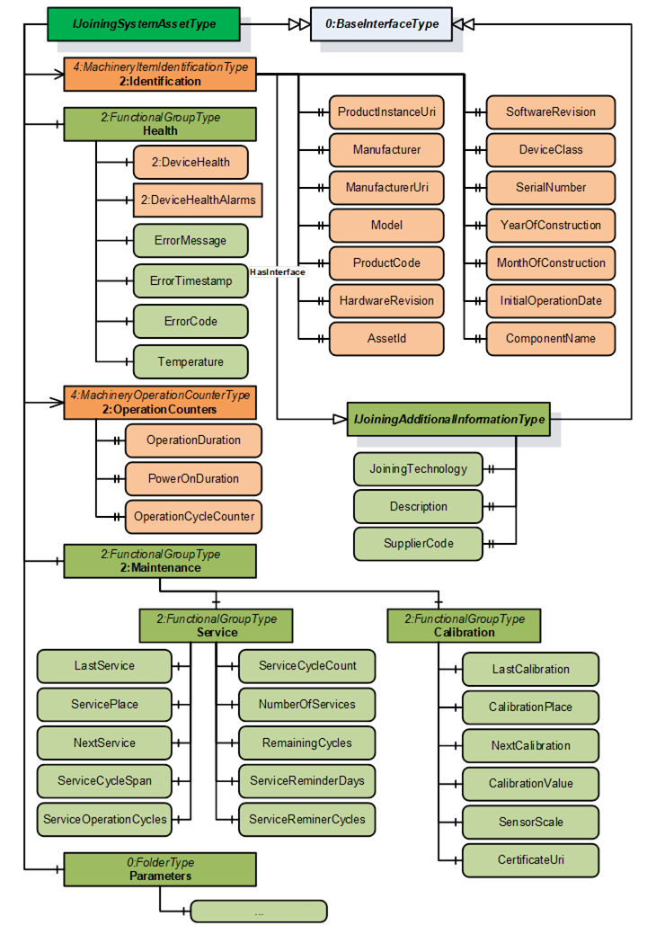
Figure 10 – Overview of Joining System Asset
This is a generic interface common for all assets in the Joining System. The purpose of this interface is to provide the common information (Example: Identification, Health, Maintenance, etc.) of all the assets in a standardized way.
This interface has a standard MachineryItemIdentificationType add-in which can be assigned with MachineIdentificationType or MachineryComponentIdentificationType for an asset based on the requirement of the system.
Note: In a Joining System, Controller and Tool instances are generally considered as Machines and other assets can be modelled as components.
To determine if an asset is classified as Machine or Component is flexible and that is achieved using base add-in from OPC UA for Machinery specification MachineryItemIdentificationType which can be specialized using MachineIdentificationType or MachineryComponentIdentificationType.
The 2:Identification Object includes parameters from MachineryItemIdentificationType (which can be specialized to MachineIdentificationType or MachineryComponentIdentificationType) defined in OPC 40001-1. It also implements IJoiningAdditionalInformationType.
Table 22 – IJoiningSystemAssetType Definition
|
Attribute |
Value |
||||
|
BrowseName |
IJoiningSystemAssetType |
||||
|
IsAbstract |
True |
||||
|
References |
Node Class |
BrowseName |
DataType |
TypeDefinition |
Other |
|
Subtype of the BaseInterfaceType defined in OPC 10000-7. |
|||||
|
0:HasAddIn |
Object |
2:Identification |
-- |
4:MachineryItemIdentificationType |
M |
|
0:HasComponent |
Object |
Health |
-- |
2:FunctionalGroupType |
O |
|
0:HasAddIn |
Object |
2:OperationCounters |
|
4:MachineryOperationCounterType |
O |
|
0:HasAddIn |
Object |
4:LifetimeCounters |
|
4:MachineryLifetimeCounterType |
O |
|
0:HasComponent |
Object |
2:Maintenance |
-- |
2:FunctionalGroupType |
O |
|
0:HasComponent |
Object |
Parameters |
-- |
0:FolderType |
O |
|
0:HasComponent |
Object |
4:MachineryBuildingBlocks |
-- |
0:FolderType |
O |
|
|
|
|
|
|
|
|
Conformance Units |
|||||
|
4:Machinery Machine Identification |
|||||
|
4:Machinery Component Identification |
|||||
|
4:Machinery Building Block Organization |
|||||
|
IJT Asset Management Health |
|||||
|
IJT Asset Management Operation Counters |
|||||
|
IJT Asset Management Service |
|||||
|
IJT Asset Management Calibration |
|||||
The components of the IJoiningSystemAssetType have additional subcomponents which are defined in Table 23.
Table 23 – IJoiningSystemAssetType Additional Subcomponents
|
Source Path |
Reference |
NodeClass |
BrowseName |
DataType |
TypeDefinition |
Others |
||
|
2:Identification |
0:HasInterface |
ObjectType |
IJoiningAdditionalInformationType |
|
|
|
||
|
2:Identification |
0:HasProperty |
Variable |
Description |
0:LocalizedText |
0:PropertyType |
O, RO |
||
|
2:Identification |
0:HasProperty |
Variable |
JoiningTechnology |
0:LocalizedText |
0:PropertyType |
O, RO |
||
|
2:Identification |
0:HasProperty |
Variable |
SupplierCode |
0:String |
0:PropertyType |
O, RO |
||
|
2:OperationCounters |
0:HasProperty |
Variable |
2:PowerOnDuration |
0:Duration |
0:PropertyType |
O, RO |
||
|
2:OperationCounters |
0:HasProperty |
Variable |
2:OperationDuration |
0:Duration |
0:PropertyType |
O, RO |
||
|
2:OperationCounters |
0:HasProperty |
Variable |
2:OperationCycleCounter |
0:UInteger |
0:PropertyType |
O, RO |
||
|
4:LifetimeCounters |
0:HasComponent |
Variable |
<LifetimeVariable> |
0:Number |
2:LifetimeVariableType |
O, RO |
||
|
Health |
0:HasInterface |
ObjectType |
2:IDeviceHealthType |
|
|
|
||
|
Health |
0:HasComponent |
Variable |
2:DeviceHealth |
2:DeviceHealthEnum |
0:BaseDataVariableType |
O, RO |
||
|
Health |
0:HasComponent |
Object |
2:DeviceHealthAlarms |
|
0:FolderType |
O, RO |
||
|
Health |
0:HasComponent |
Variable |
ErrorMessage |
0:LocalizedText |
0:BaseDataVariableType |
O, RO |
||
|
Health |
0:HasComponent |
Variable |
ErrorTimestamp |
0:UtcTime |
0:BaseDataVariableType |
O, RO |
||
|
Health |
0:HasComponent |
Variable |
ErrorCode |
0:Int64 |
0:BaseDataVariableType |
O, RO |
||
|
Health |
0:HasComponent |
Variable |
Temperature |
0:Double |
JoiningDataVariableType |
O, RO |
||
|
0:HasComponent |
Variable |
LastService |
0:UtcTime |
0:BaseDataVariableType |
M, RO |
||
|
0:HasComponent |
Variable |
ServicePlace |
0:String |
0:BaseDataVariableType |
M, RO |
||
|
0:HasComponent |
Variable |
NextService |
0:UtcTime |
0:BaseDataVariableType |
O, RO |
||
|
0:HasComponent |
Variable |
ServiceCycleSpan |
0:Int32 |
0:BaseDataVariableType |
O, RO |
||
|
0:HasComponent |
Variable |
ServiceCycleCount |
0:Int32 |
0:BaseDataVariableType |
O, RO |
||
|
0:HasComponent |
Variable |
NumberOfServices |
0:Int32 |
0:BaseDataVariableType |
O, RO |
||
|
0:HasComponent |
Variable |
ServiceReminderDays |
0:Int16 |
0:BaseDataVariableType |
O, RO |
||
|
0:HasComponent |
Variable |
RemainingCycles |
0:Int32 |
0:BaseDataVariableType |
O, RO |
||
|
0:HasComponent |
Variable |
ServiceReminderCycles |
0:Int32 |
0:BaseDataVariableType |
O, RO |
||
|
0:HasComponent |
Variable |
ServiceOperationCycles |
0:UInt64 |
0:BaseDataVariableType |
O, RO |
||
|
0:HasComponent |
Variable |
CalibrationValue |
0:Double |
0:BaseDataVariableType |
O, RO |
||
|
0:HasComponent |
Variable |
LastCalibration |
0:UtcTime |
0:BaseDataVariableType |
M, RO |
||
|
0:HasComponent |
Variable |
CalibrationPlace |
0:String |
0:BaseDataVariableType |
O, RO |
||
|
0:HasComponent |
Variable |
NextCalibration |
0:UtcTime |
0:BaseDataVariableType |
O, RO |
||
|
0:HasComponent |
Variable |
SensorScale |
0:Double |
0:BaseDataVariableType |
O, RO |
||
|
0:HasComponent |
Variable |
CertificateUri |
0:UriString |
0:BaseDataVariableType |
O, RO |
||
|
Parameters |
0:HasComponent |
Variable |
Connected |
0:Boolean |
0:BaseDataVariableType |
O, RO |
||
|
Parameters |
0:HasComponent |
Variable |
Enabled |
0:Boolean |
0:BaseDataVariableType |
O, RO |
||
|
Parameters |
0:HasComponent |
Variable |
IOSignals |
SignalDataType[] |
0:BaseDataVariableType |
O, RO |
The 2:Identification Object, using the standardized name defined in OPC 10000-100, provides identification information about the asset. This is a mandatory place holder and any asset inheriting IJoiningSystemAssetType will replace it with MachineIdentificationType or MachineryComponentIdentificationType.
The 2:Identification Object implements IJoiningAdditionalInformationType interface with the following properties:
Description is the system specific description of the asset.
Note: Although there is a description attribute at the node level in OPC UA, Description property was added at the same level as the 2:Identification node for consistency.
JoiningTechnology is a human readable text to identify the joining technology.
SupplierCode is the SAP or ERP Supplier Code of the asset.
The Health Object is an instance of 2:FunctionalGroupType to group health related parameters for all the assets in a Joining System. The parameters for Health Object are described below.
2: DeviceHealth indicates the status as defined by NAMUR Recommendation NE107. Clients can read or monitor this Variable to determine the device condition.
ErrorMessage is the user readable text of the error reported by the given asset.
ErrorTimestamp is the timestamp when the error occurred in the given asset.
ErrorCode is the system specific code for the error occurred.
Temperature is the measured temperature of the asset.
The 2:OperationCounters Object is an instance of 4:MachineryOperationCounterType which provides information about the duration something is turned on and how long it performs an activity. The parameters for 2:OperationCounters Object are defined in OPC 40001-1.
Note: The data type of 2:OperationCycleCounter is 0:UInteger and it is recommended to use 0:UInt64 for the instances of an asset in a joining system.
The 4:LifetimeCounters Object is an instance of 4:MachineryLifetimeCounterType which provides an entry point to various lifetime variables.
The <LifetimeVariable > can be used for any kind of lifetime variables.
The Maintenance Object is an instance of 2:FunctionalGroupType to group maintenance related parameters for the given asset in a Joining System. It has the following objects described below:
The Service Object provides a set of parameters related to the service operations performed on a given asset.
The Calibration Object provides a set of parameters related to the calibration operations performed on a given asset.
The parameters for Service Object are described below.
LastService is the date when the last service was completed.
ServicePlace is the location where the last service was completed.
Note: LastService and ServicePlace should have the initial operation date and the place for new assets.
NextService is the date of the next planned service.
ServiceCycleSpan is the maximum allowed number of cycles between two services.
ServiceCycleCount is the total cycle counter since the last service.
NumberOfServices is the total number of services taken place.
ServiceReminderDays is the number of days before a service reminder should be sent.
RemainingCycles is the remaining cycles before the service or maintenance. It can go negative if a service is skipped to indicate overshoot cycles.
ServiceReminderCycles is the configured threshold for the number of remaining cycles before the service reminder is sent. This is calculated based on the RemainingCycles.
Example: If ServiceReminderCycles <= RemainingCycles, then a service reminder is sent.
ServiceOperationCycles is the value of the 2:OperationCycleCounter when the last service was performed.
The parameters for Calibration Object are described below.
CalibrationValue is the configured value of the calibration.
LastCalibration is the date when the last calibration was completed.
CalibrationPlace is the location where the last calibration was completed.
NextCalibration is the date of the next planned calibration.
SensorScale is the nominal scale of the sensor. It corresponds also with the measurement range of the sensor.
CertificateUri contains the URI of a certificate of the calibration target in case the calibration target is certified and the information available. Otherwise, the Variable should be omitted. The String shall be a URI as defined by RFC 3986. Example: MCE test document.
The Parameters Object is an instance of 0:FolderType to group set of common parameters of an asset in a joining system. It has the following parameters described below:
Enabled indicates if a given asset is enabled or disabled. It can change by EnableAsset method or by some other external interface.
Connected indicates if a given asset is connected or disconnected. It can change by DisconnectAsset method or by some other external interface.
IOSignals is an array of signals available for the asset.
Note: The Parameters Object is overridden for the specific assets and contains a set of additional parameters of the given asset.
The IJoiningAdditionalInformationType provides additional parameters for 2:Identification of a given asset and is formally defined in Table 24.
Note: The descriptions of the following properties are given in section 7.2.2.2.
Table 24 – IJoiningAdditionalInformationType Definition
|
Attribute |
Value |
||||
|
BrowseName |
IJoiningAdditionalInformationType |
||||
|
IsAbstract |
True |
||||
|
References |
Node Class |
BrowseName |
DataType |
TypeDefinition |
Other |
|
Subtype of the BaseInterfaceType defined in OPC 10000-7. |
|||||
|
0:HasProperty |
Variable |
Description |
0:LocalizedText |
0:PropertyType |
O |
|
0: HasProperty |
Variable |
JoiningTechnology |
0:LocalizedText |
0:PropertyType |
O |
|
0: HasProperty |
Variable |
SupplierCode |
0:String |
0:PropertyType |
O |
|
Conformance Units |
|||||
|
IJT Asset Management Additional Information |
|||||
|
|
|||||
Table 25 – IControllerType Definition
|
Attribute |
Value |
||||
|
BrowseName |
IControllerType |
||||
|
IsAbstract |
True |
||||
|
References |
Node Class |
BrowseName |
DataType |
TypeDefinition |
Other |
|
Subtype of the IJoiningSystemAssetType, inheriting the InstanceDeclarations of that Node. |
|||||
|
0:HasComponent |
Object |
Parameters |
-- |
0:FolderType |
M |
|
Conformance Units |
|||||
|
IJT Asset Management Controller |
|||||
|
|
|||||
The components of the IControllerType have additional subcomponents which are defined in Table 26.
Table 26 – IControllerType Additional Subcomponents
|
Source Path |
Reference |
NodeClass |
BrowseName |
DataType |
TypeDefinition |
Others |
|
Parameters |
0:HasComponent |
Variable |
Type |
0:Byte |
0:MultiStateDiscreteType |
O, RO |
Type is the classification of a Controller. In Table 27, standardized values for the EnumStrings are defined. Each instance of this type shall follow the defined sequence for the entries.
Note: Servers can add additional entries into the EnumStrings array and may provide translations of the texts in different locales.
Table 27 – IControllerType Attribute values for child nodes
|
BrowsePath |
Value Attribute |
|||
|
OTHER SUPERVISORY_CONTROLLER PLC COMPUTER JOINING_PROCESS_CONTROLLER COMMUNICATION_CONTROLLER FEEDING_CONTROLLER |
The descriptions for the EnumStrings values corresponding to Type is given below:
- OTHER
- SUPERVISORY_CONTROLLER is a controller which is not executing the process or moving actuators. It manages other controllers and may be a node or hub to other controllers.
- PLC is a Programmable Logic Controller which is executing sequence operations. Examples would be part handling, providing fasteners, managing bit strokes.
- COMPUTER is an information processing unit such as PC.
- JOINING_PROCESS_CONTROLLER is controller which is handling the joining process. It performs the joining and publishes its results.
- COMMUNICATION_CONTROLLER is a controller which is mainly in charge of handling communications.
- FEEDING_CONTROLLER is a controller which performs the fastener flow and is providing the fastening elements.
It is a generic interface for any type of tool for various joining technologies. Examples: Tightening Tool, Gluing Applicator, etc.
Note: The respective joining technology specification can define a sub-type of this interface for additional properties.
Table 28 – IToolType Definition
|
Attribute |
Value |
||||
|
BrowseName |
IToolType |
||||
|
IsAbstract |
True |
||||
|
References |
Node Class |
BrowseName |
DataType |
TypeDefinition |
Other |
|
Subtype of the IJoiningSystemAssetType, inheriting the InstanceDeclarations of that Node. |
|||||
|
0:HasComponent |
Object |
Parameters |
-- |
0:FolderType |
M |
|
Conformance Units |
|||||
|
IJT Asset Management Tool |
|||||
|
IJT Asset Management Tool Operation Cycle Counter |
|||||
The components of the IToolType have additional subcomponents which are defined in Table 29.
Table 29 – IToolType Additional Subcomponents
|
Source Path |
Reference |
NodeClass |
BrowseName |
DataType |
TypeDefinition |
Others |
|
Parameters |
0:HasComponent |
Variable |
Type |
0:Byte |
0:MultiStateDiscreteType |
M, RO |
Type is the classification of a Tool.
Note: Servers can add additional entries into the EnumStrings array and may provide translations of the texts in different locales.
Table 30 – IToolType Attribute values for child nodes
|
BrowsePath |
Value Attribute |
|||
|
OTHER FIXTURED HANDHELD MANUAL |
Table 31 – IServoType Definition
|
Attribute |
Value |
||||
|
BrowseName |
IServoType |
||||
|
IsAbstract |
True |
||||
|
References |
Node Class |
BrowseName |
DataType |
TypeDefinition |
Other |
|
Subtype of the IJoiningSystemAssetType, inheriting the InstanceDeclarations of that Node. |
|||||
|
0:HasComponent |
Object |
Parameters |
-- |
0:FolderType |
M |
|
Conformance Units |
|||||
|
IJT Asset Management Servo |
|||||
|
|
|||||
The components of the IServoType have additional subcomponents which are defined in Table 32.
Table 32 – IServoType Additional Subcomponents
|
Source Path |
Reference |
NodeClass |
BrowseName |
DataType |
TypeDefinition |
Others |
|
Parameters |
0:HasComponent |
Variable |
NodeNumber |
0:Int16 |
0:BaseDataVariableType |
O, RO |
NodeNumber is the node identifier in multiple configurations. Examples: Cabinet with one controller and multiple servo/modules.
Table 33 – IMemoryDeviceType Definition
|
Attribute |
Value |
||||
|
BrowseName |
IMemoryDeviceType |
||||
|
IsAbstract |
True |
||||
|
References |
Node Class |
BrowseName |
DataType |
TypeDefinition |
Other |
|
Subtype of the IJoiningSystemAssetType, inheriting the InstanceDeclarations of that Node. |
|||||
|
0:HasComponent |
Object |
Parameters |
-- |
0:FolderType |
M |
|
Conformance Units |
|||||
|
IJT Asset Management Memory Device |
|||||
|
|
|||||
The components of the IMemoryDeviceType have additional subcomponents which are defined in Table 34.
Table 34 – IMemoryDeviceType Additional Subcomponents
|
Source Path |
Reference |
NodeClass |
BrowseName |
DataType |
TypeDefinition |
Others |
|
Parameters |
0:HasComponent |
Variable |
Type |
0:String |
0:BaseDataVariableType |
O, RO |
|
Parameters |
0:HasComponent |
Variable |
StorageCapacity |
0:UInt64 |
0:BaseDataVariableType |
O, RO |
|
Parameters |
0:HasComponent |
Variable |
UsedSpace |
0:UInt64 |
0:BaseDataVariableType |
O, RO |
Type is the type of memory device. It may define the form factor, interface, or technology. Examples: Flash, CFAST, USB, etc.
Note: Memory or storage devices can be classified based on various factors. Hence an open string is provided to make it generic.
StorageCapacity is the static information on size of the storage in Bytes.
UsedSpace is the static information on size of the used space in Bytes.
Table 35 – ISensorType Definition
|
Attribute |
Value |
||||
|
BrowseName |
ISensorType |
||||
|
IsAbstract |
True |
||||
|
References |
Node Class |
BrowseName |
DataType |
TypeDefinition |
Other |
|
Subtype of the IJoiningSystemAssetType, inheriting the InstanceDeclarations of that Node. |
|||||
|
0:HasComponent |
Object |
Parameters |
-- |
0:FolderType |
M |
|
Conformance Units |
|||||
|
IJT Asset Management Sensor |
|||||
|
|
|||||
The components of the ISensorType have additional subcomponents which are defined in Table 36.
Table 36 – ISensorType Additional Subcomponents
|
Source Path |
Reference |
NodeClass |
BrowseName |
DataType |
TypeDefinition |
Others |
|
Parameters |
0:HasComponent |
Variable |
Type |
0:Byte |
0:MultiStateDiscreteType |
O, RO |
|
Parameters |
0:HasComponent |
Variable |
OverloadCount |
0:Int64 |
0:BaseDataVariableType |
O, RO |
|
Parameters |
0:HasComponent |
Variable |
MeasuredValue |
0:Double |
JoiningDataVariableType |
O, RO |
|
|
|
|
|
|
|
|
Type is the classification of a Sensor. In Table 37, standardized values for the EnumStrings are defined. Each instance of this type shall follow the defined sequence for the entries.
Note: Servers can add additional entries into the EnumStrings array and may provide translations of the texts in different locales.
Table 37 – ISensorType Attribute values for child nodes
|
BrowsePath |
Value Attribute |
|||
|
OTHER TIME TORQUE ANGLE IMPULSE DISTANCE AREA VOLUME FORCE PRESSURE VOLTAGE CURRENT RESISTANCE POWER ENERGY MASS TEMPERATURE FREQUENCY JOLT VIBRATION NUMBER LINEAR_SPEED ANGULAR_SPEED LINEAR_ACCELERATION ANGULAR_ACCELERATION TORQUE_SPEED TORQUE_ACCELERATION |
OverloadCount is the number of overloads of the sensor, where the permissible load of the senor was exceeded.
MeasuredValue is the actual measured value reported from a sensor.
Note: An instance of Sensor can be referenced to a respective Calibration Target which was used to calibrate the sensor. The standard models for Calibration Target are defined in OPC 10000-200.
Table 38 – ICableType Definition
|
Attribute |
Value |
||||
|
BrowseName |
ICableType |
||||
|
IsAbstract |
True |
||||
|
References |
Node Class |
BrowseName |
DataType |
TypeDefinition |
Other |
|
Subtype of the IJoiningSystemAssetType, inheriting the InstanceDeclarations of that Node. |
|||||
|
0:HasComponent |
Object |
Parameters |
-- |
0:FolderType |
M |
|
Conformance Units |
|||||
|
IJT Asset Management Cable |
|||||
|
|
|||||
The components of the ICableType have additional subcomponents which are defined in Table 39.
Table 39 – ICableType Additional Subcomponents
|
Source Path |
Reference |
NodeClass |
BrowseName |
DataType |
TypeDefinition |
Others |
|
Parameters |
0:HasComponent |
Variable |
Type |
0:Byte |
0:MultiStateDiscreteType |
O, RO |
|
Parameters |
0:HasComponent |
Variable |
CableLength |
0:Double |
JoiningDataVariableType |
O, RO |
Type is the classification of the cable.
In Table 40, standardized values for the EnumStrings are defined. Each instance of this type shall follow the defined sequence for the entries.
Note: Servers can add additional entries into the EnumStrings array and may provide translations of the texts in different locales.
Table 40 – ICableType Attribute values for child nodes
|
BrowsePath |
Value Attribute |
|||
|
OTHER TOOL_CABLE SENSOR_CABLE COMMUNICATION_CABLE POWER_CABLE IO_CABLE BUS_CABLE |
CableLength is the length of the cable.
Table 41 – IBatteryType Definition
|
Attribute |
Value |
||||
|
BrowseName |
IBatteryType |
||||
|
IsAbstract |
True |
||||
|
References |
Node Class |
BrowseName |
DataType |
TypeDefinition |
Other |
|
Subtype of the IJoiningSystemAssetType, inheriting the InstanceDeclarations of that Node. |
|||||
|
0:HasComponent |
Object |
Parameters |
-- |
0:FolderType |
M |
|
Conformance Units |
|||||
|
IJT Asset Management Battery |
|||||
|
IJT Asset Management Battery Operation Cycle Counter |
|||||
The components of the IBatteryType have additional subcomponents which are defined in Table 42.
Table 42 – IBatteryType Additional Subcomponents
|
Source Path |
Reference |
NodeClass |
BrowseName |
DataType |
TypeDefinition |
Others |
|
Parameters |
0:HasComponent |
Variable |
NominalVoltage |
0:Double |
JoiningDataVariableType |
M, RO |
|
Parameters |
0:HasComponent |
Variable |
Capacity |
0:Double |
JoiningDataVariableType |
M, RO |
|
Parameters |
0:HasComponent |
Variable |
ChargeCycleCount |
0:Int64 |
0:BaseDataVariableType |
O, RO |
|
Parameters |
0:HasComponent |
Variable |
StateOfCharge |
0:Byte |
0:BaseDataVariableType |
O, RO |
|
Parameters |
0:HasComponent |
Variable |
StateOfHealth |
0:Byte |
0:BaseDataVariableType |
O, RO |
|
Parameters |
0:HasComponent |
Variable |
Type |
0:String |
0:BaseDataVariableType |
O, RO |
NominalVoltage is the nominal DC voltage of the battery.
Capacity is the nominal capacity of the battery.
ChargeCycleCount is the number of times the battery has been charged since the initial operation date.
StateOfCharge is the state of charge (SOC) indicator functions as a sort of fuel gauge that displays the usable amount of energy. This helps determine optimal charging and discharging. It is given in percentage.
StateOfHealth is the State of Health is a measurement that reflects the general condition of a battery and its ability to deliver the specified performance compared with a fresh battery. It considers such factors as charge acceptance, internal resistance, voltage, and self-discharge. It is given in percentage.
Type is a user readable text to determine the type of battery such as pack type, technology, chemical composition, battery standard, etc.
Table 43 – IPowerSupplyType Definition
|
Attribute |
Value |
||||
|
BrowseName |
IPowerSupplyType |
||||
|
IsAbstract |
True |
||||
|
References |
Node Class |
BrowseName |
DataType |
TypeDefinition |
Other |
|
Subtype of the IJoiningSystemAssetType, inheriting the InstanceDeclarations of that Node. |
|||||
|
0:HasComponent |
Object |
Parameters |
-- |
0:FolderType |
M |
|
Conformance Units |
|||||
|
IJT Asset Management Power Supply |
|||||
|
|
|||||
The components of the IPowerSupplyType have additional subcomponents which are defined in Table 44.
Table 44 – IPowerSupplyType Additional Subcomponents
|
Source Path |
Reference |
NodeClass |
BrowseName |
DataType |
TypeDefinition |
Others |
|
Parameters |
0:HasComponent |
Variable |
InputSpecification |
0:String |
0:BaseDataVariableType |
M, RO |
|
Parameters |
0:HasComponent |
Variable |
OutputSpecification |
0:String |
0:BaseDataVariableType |
O, RO |
|
Parameters |
0:HasComponent |
Variable |
NominalPower |
0:Double |
JoiningDataVariableType |
O, RO |
|
Parameters |
0:HasComponent |
Variable |
ActualPower |
0:Double |
JoiningDataVariableType |
O, RO |
InputSpecification is the input specification of the power supply. Example: 230 V, 50/60 Hz, 10 A.
OutputSpecification is the output specification of the power supply.
NominalPower is the maximum output power of the power supply.
ActualPower is the actual load consumption of the power supply.
Note: This value may not be exposed in the highest possible sample rate. This value is for information only and should not be used for real time processing.
Table 45 – IFeederType Definition
|
Attribute |
Value |
||||
|
BrowseName |
IFeederType |
||||
|
IsAbstract |
True |
||||
|
References |
Node Class |
BrowseName |
DataType |
TypeDefinition |
Other |
|
Subtype of the IJoiningSystemAssetType, inheriting the InstanceDeclarations of that Node. |
|||||
|
0:HasComponent |
Object |
Parameters |
-- |
0:FolderType |
M |
|
Conformance Units |
|||||
|
IJT Asset Management Feeder |
|||||
|
|
|||||
The components of the IFeederType have additional subcomponents which are defined in Table 46.
Table 46 – IFeederType Additional Subcomponents
|
Source Path |
Reference |
NodeClass |
BrowseName |
DataType |
TypeDefinition |
Others |
|
Parameters |
0:HasComponent |
Variable |
Type |
0:Byte |
0:MultiStateDiscreteType |
O, RO |
|
Parameters |
0:HasComponent |
Variable |
Material |
0:String |
0:BaseDataVariableType |
M, RO |
|
Parameters |
0:HasComponent |
Variable |
FillLevel |
0:Byte |
0:BaseDataVariableType |
O, RO |
|
Parameters |
0:HasComponent |
Variable |
FeedingSpeed |
0:Double |
JoiningDataVariableType |
O, RO |
Type is the classification of a Feeder. In Table 47, standardized values for the EnumStrings are defined. Each instance of this type shall follow the defined sequence for the entries.
Note: Servers can add additional entries into the EnumStrings array and may provide translations of the texts in different locales.
Table 47 – IFeederType Attribute values for child nodes
|
BrowsePath |
Value Attribute |
|||
|
OTHER BOWL BUNKER CONVEYOR DRUM LINEAR SWORD TAPE MAGAZINE |
Material is the type or name of the part which is supplied by the feeder.
FillLevel is the fill level in the feeder in percentage [%]. (0%=empty, 100% = full).
FeedingSpeed indicates the output in parts per time. Example: fasteners / second.
Table 48 – IAccessoryType Definition
|
Attribute |
Value |
||||
|
BrowseName |
IAccessoryType |
||||
|
IsAbstract |
True |
||||
|
References |
Node Class |
BrowseName |
DataType |
TypeDefinition |
Other |
|
Subtype of the IJoiningSystemAssetType, inheriting the InstanceDeclarations of that Node. |
|||||
|
0:HasComponent |
Object |
Parameters |
-- |
0:FolderType |
M |
|
Conformance Units |
|||||
|
IJT Asset Management Accessory |
|||||
|
|
|||||
The components of the IAccessoryType have additional subcomponents which are defined in Table 49.
Table 49 – IAccessoryType Additional Subcomponents
|
Source Path |
Reference |
NodeClass |
BrowseName |
DataType |
TypeDefinition |
Others |
|
Parameters |
0:HasComponent |
Variable |
Type |
0:String |
0:BaseDataVariableType |
O, RO |
Type is a user readable open string to describe the type of accessory such as socket selector, operator panel, etc.
Table 50 – ISubComponentType Definition
|
Attribute |
Value |
||||
|
BrowseName |
ISubComponentType |
||||
|
IsAbstract |
True |
||||
|
References |
Node Class |
BrowseName |
DataType |
TypeDefinition |
Other |
|
Subtype of the IJoiningSystemAssetType, inheriting the InstanceDeclarations of that Node. |
|||||
|
0:HasComponent |
Object |
Parameters |
-- |
0:FolderType |
O |
|
Conformance Units |
|||||
|
IJT Asset Management SubComponent |
|||||
|
|
|||||
The components of the ISubComponentType have additional subcomponents which are defined in Table 51.
Table 51 – ISubComponentType Additional Subcomponents
|
Source Path |
Reference |
NodeClass |
BrowseName |
DataType |
TypeDefinition |
Others |
|
Parameters |
0:HasComponent |
Variable |
Type |
0:String |
0:BaseDataVariableType |
O, RO |
Type is a user readable open string to describe the type of subcomponent such as network module, etc.
Table 52 – ISoftwareType Definition
|
Attribute |
Value |
||||
|
BrowseName |
ISoftwareType |
||||
|
IsAbstract |
True |
||||
|
References |
Node Class |
BrowseName |
DataType |
TypeDefinition |
Other |
|
Subtype of the IJoiningSystemAssetType, inheriting the InstanceDeclarations of that Node. |
|||||
|
|
|
|
|
|
|
|
Conformance Units |
|||||
|
IJT Asset Management Software |
|||||
|
|
|||||
Note: The instance of a Software most likely contains only the following parameters from IJoiningSystemAssetType, other parameters may not be applicable.
- Identification / ProductInstanceUri
- Identification / Manufacturer
- Identification / ManufacturerUri
- Identification / Model
- Identification / SoftwareRevision
- Identification / ComponentName
- Identification / ProductCode
- Identification / SerialNumber
- Identification / JoiningTechnology
Table 53 – IVirtualStationType Definition
|
Attribute |
Value |
||||
|
BrowseName |
IVirtualStationType |
||||
|
IsAbstract |
True |
||||
|
References |
Node Class |
BrowseName |
DataType |
TypeDefinition |
Other |
|
Subtype of the IJoiningSystemAssetType, inheriting the InstanceDeclarations of that Node. |
|||||
|
|
|
|
|
|
|
|
Conformance Units |
|||||
|
IJT Asset Management Virtual Station |
|||||
|
|
|||||
Note: The instance of a Virtual Station most likely contains only the following parameters from IJoiningSystemAssetType, other parameters may not be applicable.
- Identification / ProductInstanceUri
- Identification / Manufacturer
- Identification / ManufacturerUri
- Identification / ComponentName
- Identification / JoiningTechnology
- Identification / SerialNumber
- Note: SerialNumber is Mandatory from the MachineryItemIdentificationType and may not be applicable for a Virtual Station. Hence, it can be set to an empty value.
The Method Result Codes (defined in Call Service) are defined in Table 54. It shows the possible values for the Method call result codes.
Table 54 – Possible Method Result Codes
|
Result Code |
Description |
|
Good |
The Method execution was successful, and the Status parameter indicates the successful operation. |
|
Uncertain |
The Method execution was successful, and the Status parameter indicates an error. |
|
Bad_UserAccessDenied |
The user does not have the right to execute the Method. The client shall not evaluate the Status parameter. |
|
Bad_UnexpectedError |
The server is not able to execute the function because an unexpected error occurred. The Server might be temporarily unavailable or unreachable due to network failure. The client shall not evaluate the Status parameter. |
Table 55 shows the possible values for the Status parameter.
Note: The client shall not evaluate the Status parameter if the Method Result Code is Bad.
Table 55 – Possible Status Parameter Values
|
Status |
Description |
|
< 0 |
Shall be used for application-specific errors. |
|
> 0 |
Reserved for errors defined by this and future standards. |
|
0 |
OK/Success. |
|
1 |
NOT_OK – Generic Error. |
|
2 |
ProductInstanceUri not found. |
|
3 |
ProductInstanceUri not applicable. |
|
4 |
Input identifier/entity not found. |
|
5 |
Invalid input. |