
6 OPC UA Joining System Information Model Overview
6.1 Joining System
A joining system is a container to group set of information and methods into a logic unit.
Each joining system consists of various modules for Asset Management, Result Management, Joining Process Management, Joint Management and respective Events and Alarms. Each of the modules provides a set of methods for external systems to interact with the joining system.
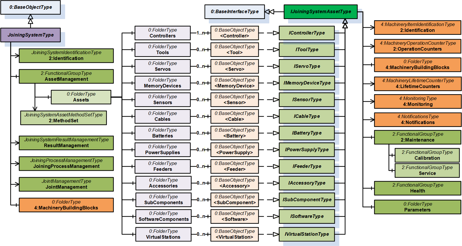
6.2 Asset Management
Asset Management is a container to group a set of assets and the respective methods.
6.2.1 Assets
Assets is a container which provides all the assets in a joining system described in the following sections.
6.2.1.1 Overview
The assets are modelled using the generic object declaration BaseObjectType place holders to ensure interoperability from various other domain specifications.
This specification defines a set of interfaces for each type of asset and asset instances can be implemented by including the required interfaces defined in this specification. The asset instances can also be modelled by external interfaces from other companion specifications or vendor specific extensions with the help of open generic model.
Note: For Accessories and SubComponents, there can be other companion specifications (Example: Stack light) and these models could be implemented at instance level since the assets are modelled as BaseObjectType placeholders.
This version of the specification is limited to assets which can expose data.
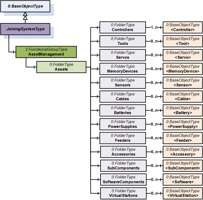
6.2.1.2 Controllers
This is a container for the set of controllers in the system.
A controller can represent an entity that can control an aspect of the joining process. A controller can also be any kind of supervisory instance, which manages multiple tools. So, controller can be any kind of computation device which controls specific parts of the joining system and communicates to another system. A joining system may consist of multiple controller instances. The first controller in the list is intended to harbor the OPC UA communication for the Joining System information model.
6.2.1.3 Tools
This is a container for the set of tools in the system.
A tool represents a physical device that joins parts together. It can for example be a tool held by a human being, spindle attached to a robot or be part of a tool fixture.
Note: Spindle is a common term used in a fixtured system to represent a specific type of Tool.
6.2.1.4 Servos
This is a container for the set of servos in the system.
A servo amplifier represents a physical device that controls the motor in the tool. It is the physical power stage to deliver the power to the motor to perform the joining or some other movement in the system.
6.2.1.5 MemoryDevices
This is a container for the set of memory devices in the system.
A MemoryDevice (or Storage Device) stores data, such as, the system identity, the software of the system, licenses, joining programs, etc.
Those memory devices may be implemented, for example like memory cards or memory modules. Those are used to store data also during the power off phase of the device.
6.2.1.6 Sensors
This is a container for the set of sensors in the system.
A sensor is a physical device whose measurements can be transformed and processed within a given system.
Each sensor is responsible for one measurement signal. Therefore, it measures one quantity and delivers the value by doing so.
The sensor data may be used in the system to perform the joining but also can deliver other information of the system.
Besides the measured quantity the sensor may expose its calibration information, which may be useful for quality assessment.
6.2.1.7 Cables
This is a container for the set of cables in the system.
Cables interconnect certain parts of the system. Example: Cable from a tool to a controller.
Note: Cables are only modelled in the system if the required information can be provided by the system.
6.2.1.8 Batteries
This is a container for the set of batteries in the system.
Battery is a physical device which stores and provides energy to the required system.
Note: Batteries are only modelled in the system if the required information can be provided by the system.
6.2.1.9 PowerSupplies
This is a container for the set of power supplies in the system.
A power supply is a physical device which typically transforms or delivers power.
6.2.1.10 Feeders
This is a container for the set of feeders in the system.
A feeder supplies the material for the joining process. It may stock fasteners and separate the elements and makes them available at the joint position.
Examples: Bunker, bowl feeder, step feeder, etc.
6.2.1.11 Accessories
This is a container for the set of accessories in the system.
Accessory represents a physical device mounted on the tool or in the station to help understand or influence the workflow.
Examples: Stack lights, socket selectors, screens, scanners, location tags, reaction bars, operator panel, etc.
6.2.1.12 SubComponents
This is a container for the list of subcomponents in the system.
A subcomponent is a system-specific part that can be plug-in or permanently installed and enables the joining system to perform a specific task.
Note: These are the type of assets which cannot be modelled by the other assets defined in this specification.
Examples: Radio modules, fieldbus modules, etc.
6.2.1.13 SoftwareComponents
This is a container for the list of software in the system.
A software component is a system-specific software asset that can be part of any physical asset.
6.2.1.14 VirtualStations
This is a container for the list of virtual stations in the system.
A virtual station is a system-specific abstraction which can be used to group and manage processes and physical assets.
6.3 Condition Monitoring
The data related to condition monitoring is provided as part of the asset information model. Refer section 7.3.2 for details.
6.4 Event Management
This specification defines standard payload and classification for an event or condition from a joining system. Refer section 8 for details.
6.5 Result Management
Result is the outcome of the joining operation.
Joining Result includes optional elements such as step results, traces, errors, and additional information to reference the related objects like joining processes, joints, assets, etc.
The joining system can send a single result, or a group of results to evaluate the outcome of a joining process.
Note:
The Result Management model extends the model from OPC 40001-101 – Machinery Result Transfer specification.
For the systems which do not support multiple steps in a joining process, Result can be modelled as a single step.
6.6 Joining Process Management
It provides a standardized way to manage joining processes in a joining system by defining a generic container for various joining processes and set of methods to interact with the joining system.
6.7 Joint Management
It provides a standardized way to manage joints handled by the joining system by using a joint model and set of methods to interact with the joining system.