
5 General information about Geometric Measurement Systems (GMS) and OPC UA
5.1 Introduction to Geometric Measurement Systems in Industrial Production
Metrology is an important provider of information in industrial production. Therefore, its integration into the digital data flow of information in production is obvious. The most common application of metrology is its use for quality inspection.
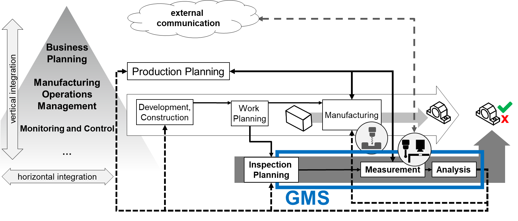
Figure 1 shows a simplified representation of the process chain for order processing in production from development and construction to work planning (routing) and to manufacturing. This process is connected to the process of quality inspection based on measurements from inspection, (test) planning to measurement and to analysis. All process steps are managed by production planning. The feedback of data from the analysis into upstream processes are marked with dashed lines [Pfeifer 2006]. An additional line represents the connection between the measurement system and external instances.
Besides the horizontal integration along the process chain of production, a vertical integration into upper management exists. This integration can be described by the levels of automation pyramid according to [IEC 62264-1].
The scope of the Geometric Measurement System companion specification is marked with "GMS".
A large proportion of the measurements in production are measurements on the part geometry.
5.1.1 Definition of a Geometric Measurement System
The International Vocabulary for Metrology (VIM) [JCGM 200] defines the general concepts and the associated terms for metrology. Chapter 3 of VIM describes devices for measurement. A measuring instrument is thus a device used for making measurements, alone or with one or more supplementary devices. A measuring system consists of a set of one or more measuring instruments and often other devices, including any reagent and supply, assembled and adapted to give information used to generate measured quantity values within specified intervals for quantities of specified kinds. A measuring system may even consist of one single measuring instrument only.
The standards of Geometrical Product Specification (ISO GPS) are used to define the geometric requirements for workpieces in technical specifications and the requirements for their verification [ISO 14638]. The verification is mainly done by measurements. General concepts and requirements for the used measuring equipment define ISO 14978. The described measuring equipment is also called a measuring system. This leads to the term Geometric Measurement System (GMS). A GMS is a measuring system according to [JCGM 200] performing geometrical measuring tasks. The measurement in production is often automated.
OPC UA offers the opportunity to integrate GMS into production according to the described path in Figure 1.
5.1.2 Classification and Structure of Geometric Measurement Systems
The field of Geometric Measurement Systems is very broad. In this section, the components of a GMS, as well as a classification for possible implementations, will be shown. The structures described here are exemplary. There may be further or future classifications for which this Companion Specification can still be used, and a GMS may contain further components or subsystems. Figure 2 contains an overview of the common components. It does not claim to be complete.
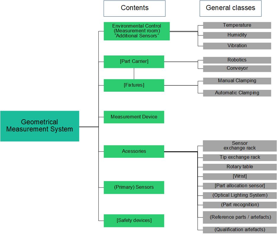
According to Figure 2, there are seven different main types of common components of a GMS (green). They may also be split into different subtypes (grey). The main types are defined as:
The GMS consists of an instrument that comprises one or more sensors (4.2.7).
Environmental control [VDI 2627] requires additional sensors (4.2.8)).
Part carrier & fixtures: enable a strict control and fixed reference in space and time - the coordinate systems - between measured component and measurement system.
Accessories enable the GMS to function according to the production plan.
Safety devices enable the GMS to observe its environment and prevent it from harming the operator or the measured part.
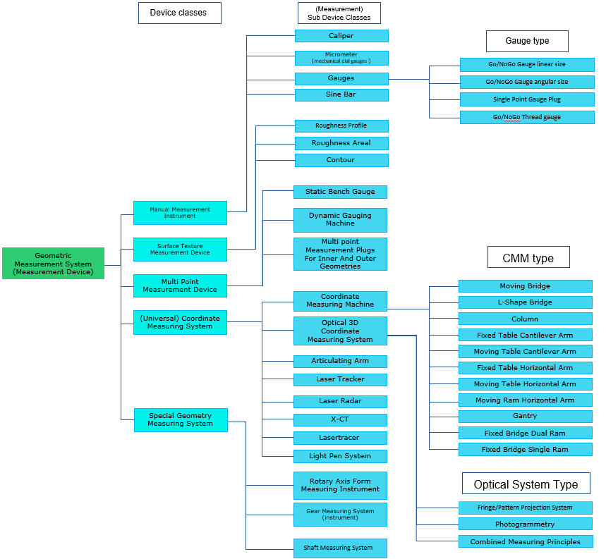
Figure 3 contains the classification of a GMS and divide the GMS into manual measurement instruments [ISO 14978], surface texture measuring instruments [ISO 25178], multi point measuring instruments, coordinate measuring systems [ISO 10360] and special systems. The gauges [ISO 1938] are treated as manual instruments. The list of applicable GMS does not claim to be complete.
5.1.3 Result Management in Geometric Measurement Systems
The output of all measurement systems are measurement results. For geometric measurement results, many file formats and structures (e.g., AQDEF® [AQDEF 5], DMIS [ISO 22093], QIF, I++ DMS, ...) and other generic formats (CSV, raw text, JSON, XML …) are used. All these formats have their specific use cases, domains, and benefits [Pfeifer 2006]. Therefore, this Companion Specification defines only the transport and the management of the result. The concepts of the result management are based on the Result Management of the OPC 40001-101.
5.2 Introduction to OPC Unified Architecture
5.2.1 What is OPC UA?
OPC UA is an open and royalty free set of standards designed as a universal communication protocol. While there are numerous communication solutions available, OPC UA has key advantages:
A state of art security model (see OPC 10000-2).
A fault tolerant communication protocol.
An information modelling framework that allows application developers to represent their data in a way that makes sense to them.
OPC UA has a broad scope which delivers for economies of scale for application developers. This means that a larger number of high-quality applications at a reasonable cost are available. When combined with semantic models such as OPC UA for Geometric Measurement Systems, OPC UA makes it easier for end users to access data via generic commercial applications.
The OPC UA model is scalable from small devices to ERP systems. OPC UA Servers process information locally and then provide that data in a consistent format to any application requesting data - ERP, MES, PMS, Maintenance Systems, HMI, Smartphone or a standard Browser, for examples. For a more complete overview see OPC 10000-1.
5.2.2 Basics of OPC UA
As an open standard, OPC UA is based on standard internet technologies, like TCP/IP, HTTP, Web Sockets.
As an extensible standard, OPC UA provides a set of Services (see OPC 10000-4) and a basic information model framework. This framework provides an easy manner for creating and exposing vendor defined information in a standard way. More importantly all OPC UA Clients are expected to be able to discover and use vendor-defined information. This means OPC UA users can benefit from the economies of scale that come with generic visualization and historian applications. This specification is an example of an OPC UA Information Model designed to meet the needs of developers and users.
OPC UA Clients can be any consumer of data from another device on the network to browser based thin clients and ERP systems. The full scope of OPC UA applications is shown in Figure 4.

OPC UA provides a robust and reliable communication infrastructure having mechanisms for handling lost messages, failover, heartbeat, etc. With its binary encoded data, it offers a high-performing data exchange solution. Security is built into OPC UA as security requirements become more and more important especially since environments are connected to the office network or the internet and attackers are starting to focus on automation systems.
5.2.3 Information modelling in OPC UA
5.2.3.1 Concepts
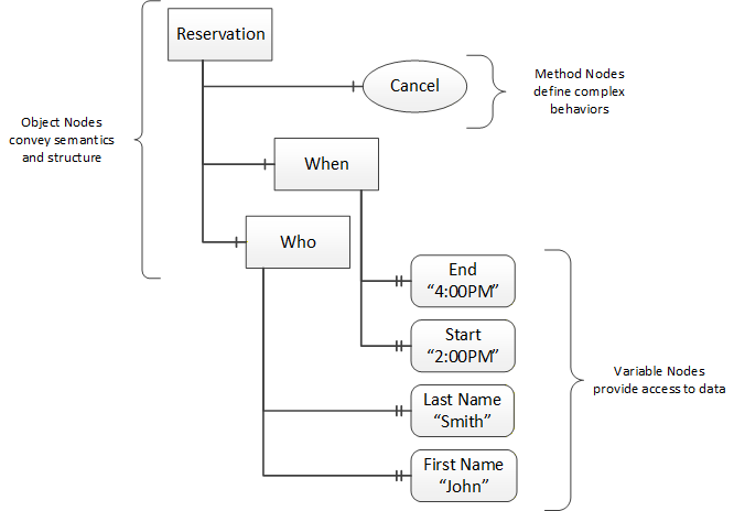
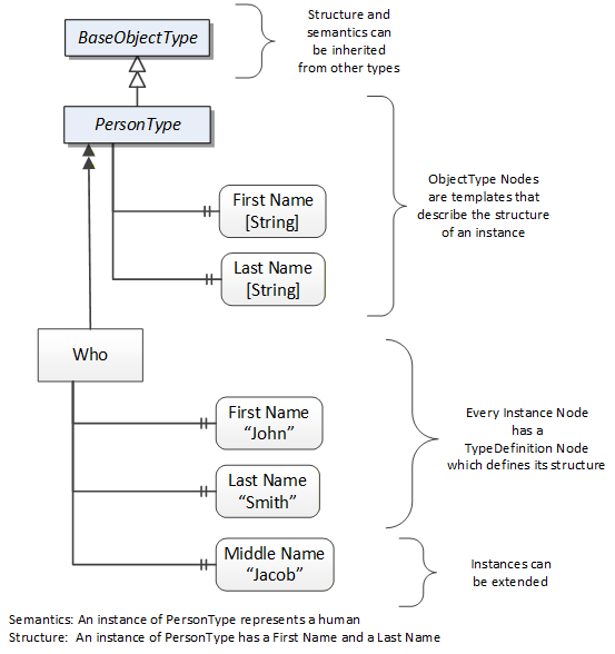
OPC UA provides a framework that can be used to represent complex information as Objects in an AddressSpace which can be accessed with standard services. These Objects consist of Nodes connected by References. Different classes of Nodes convey different semantics. For example, a Variable Node represents a value that can be read or written. The Variable Node has an associated DataType that can define the actual value, such as a string, float, structure etc. It can also describe the Variable value as a variant. A Method Node represents a function that can be called. Every Node has a number of Attributes including a unique identifier called a NodeId and non-localized name called as BrowseName. An Object representing a 'Reservation' is shown in Figure 5.
Object and Variable Nodes represent instances and they always reference a TypeDefinition (ObjectType or VariableType) Node which describes their semantics and structure. Figure 6 illustrates the relationship between an instance and its TypeDefinition.
The type Nodes are templates that define all of the children that can be present in an instance of the type. In the example in Figure 6 the PersonType ObjectType defines two children: First Name and Last Name. All instances of PersonType are expected to have the same children with the same BrowseNames. Within a type the BrowseNames uniquely identify the children. This means Client applications can be designed to search for children based on the BrowseNames from the type instead of NodeIds. This eliminates the need for manual reconfiguration of systems if a Client uses types that multiple Servers implement.
OPC UA also supports the concept of sub-typing. This allows a modeller to take an existing type and extend it. There are rules regarding sub-typing defined in OPC 10000-3, but in general they allow the extension of a given type or the restriction of a DataType. For example, the modeller may decide that the existing ObjectType in some cases needs an additional Variable. The modeller can create a subtype of the ObjectType and add the Variable. A Client that is expecting the parent type can treat the new type as if it was of the parent type. Regarding DataTypes, subtypes can only restrict. If a Variable is defined to have a numeric value, a sub type could restrict it to a float.
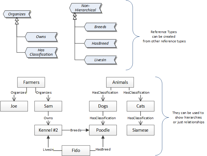
References allow Nodes to be connected in ways that describe their relationships. All References have a ReferenceType that specifies the semantics of the relationship. References can be hierarchical or non-hierarchical. Hierarchical references are used to create the structure of Objects and Variables. Non-hierarchical are used to create arbitrary associations. Applications can define their own ReferenceType by creating subtypes of an existing ReferenceType. Subtypes inherit the semantics of the parent but may add additional restrictions. Figure 7 depicts several References, connecting different Objects.
The Figures above use a notation that was developed for the OPC UA specification. The notation is summarized in Figure 8. UML representations can also be used; however, the OPC UA notation is less ambiguous because there is a direct mapping from the elements in the Figures to Nodes in the AddressSpace of an OPC UA Server.

A complete description of the different types of Nodes and References can be found in OPC 10000-3 and the base structure is described in OPC 10000-5.
OPC UA specification defines a very wide range of functionality in its basic information model. It is not required that all Clients or Servers support all functionality in the OPC UA specifications. OPC UA includes the concept of Profiles, which segment the functionality into testable certifiable units. This allows the definition of functional subsets (that are expected to be implemented) within a companion specification. The Profiles do not restrict functionality, but generate requirements for a minimum set of functionalities (see OPC 10000-7).
5.2.3.2 Namespaces
OPC UA allows information from many different sources to be combined into a single coherent AddressSpace. Namespaces are used to make this possible by eliminating naming and id conflicts between information from different sources. Each namespace in OPC UA has a globally unique string called a NamespaceUri which identifies a naming authority and a locally unique integer called a NamespaceIndex, which is an index into the Server's table of NamespaceUris. The NamespaceIndex is unique only within the context of a Session between an OPC UA Client and an OPC UA Server- the NamespaceIndex can change between Sessions and still identify the same item even though the NamespaceUri's location in the table has changed. The Services defined for OPC UA use the NamespaceIndex to specify the Namespace for qualified values.
There are two types of structured values in OPC UA that are qualified with NamespaceIndexes: NodeIds and QualifiedNames. NodeIds are locally unique (and sometimes globally unique) identifiers for Nodes. The same globally unique NodeId can be used as the identifier in a node in many Servers - the node's instance data may vary but its semantic meaning is the same regardless of the Server it appears in. This means Clients can have built-in knowledge of what the data means in these Nodes. OPC UA Information Models generally define globally unique NodeIds for the TypeDefinitions defined by the Information Model.
QualifiedNames are non-localized names qualified with a Namespace. They are used for the BrowseNames of Nodes and allow the same names to be used by different information models without conflict. TypeDefinitions are not allowed to have children with duplicate BrowseNames; however, instances do not have that restriction.
5.2.3.3 Companion Specifications
An OPC UA companion specification for an industry specific vertical market describes an Information Model by defining ObjectTypes, VariableTypes, DataTypes and ReferenceTypes that represent the concepts used in the vertical market, and potentially also well-defined Objects as entry points into the AddressSpace.