Metrology is an important provider of information in industrial production. Therefore, its integration into the digital data flow of information in production is obvious. The most common application of metrology is its use for quality inspection.
Figure 1 shows a simplified representation of the process chain for order processing in production from development and construction to work planning (routing) and to manufacturing. This process is connected to the process of quality inspection based on measurements from inspection, (test) planning to measurement and to analysis. All process steps are managed by production planning. The feedback of data from the analysis into upstream processes are marked with dashed lines [Pfeifer 2006]. An additional line represents the connection between the measurement system and external instances.
Besides the horizontal integration along the process chain of production, a vertical integration into upper management exists. This integration can be described by the levels of automation pyramid according to [IEC 62264-1].
The scope of the Geometric Measurement System companion specification is marked with "GMS".
A large proportion of the measurements in production are measurements on the part geometry.
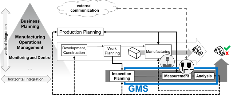
Figure 1 – Overview of a Geometric Measurement System (GMS) and its integration into the production environment
The International Vocabulary for Metrology (VIM) [JCGM 200] defines the general concepts and the associated terms for metrology. Chapter 3 of VIM describes devices for measurement. A measuring instrument is thus a device used for making measurements, alone or with one or more supplementary devices. A measuring system consists of a set of one or more measuring instruments and often other devices, including any reagent and supply, assembled and adapted to give information used to generate measured quantity values within specified intervals for quantities of specified kinds. A measuring system may even consist of one single measuring instrument only.
The standards of Geometrical Product Specification (ISO GPS) are used to define the geometric requirements for workpieces in technical specifications and the requirements for their verification [ISO 14638]. The verification is mainly done by measurements. General concepts and requirements for the used measuring equipment define ISO 14978. The described measuring equipment is also called a measuring system. This leads to the term Geometric Measurement System (GMS). A GMS is a measuring system according to [JCGM 200] performing geometrical measuring tasks. The measurement in production is often automated.
OPC UA offers the opportunity to integrate GMS into production according to the described path in Figure 1.
The field of Geometric Measurement Systems is very broad. In this section, the components of a GMS, as well as a classification for possible implementations, will be shown. The structures described here are exemplary. There may be further or future classifications for which this Companion Specification can still be used, and a GMS may contain further components or subsystems. Figure 2 contains an overview of the common components. It does not claim to be complete.
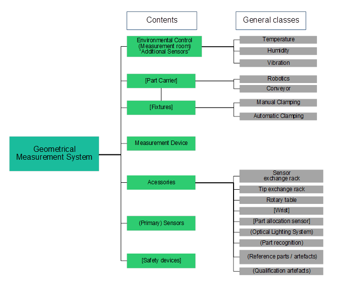
According to Figure 2, there are seven different main types of common components of a GMS (green). They may also be split into different subtypes (grey). The main types are defined as:
- The GMS consists of an instrument that comprises one or more sensors (4.2.7).
- Environmental control [VDI 2627] requires additional sensors (4.2.8)).
- Part carrier & fixtures: enable a strict control and fixed reference in space and time - the coordinate systems - between measured component and measurement system.
- Accessories enable the GMS to function according to the production plan.
- Safety devices enable the GMS to observe its environment and prevent it from harming the operator or the measured part.
Figure 3 contains the classification of a GMS and divide the GMS into manual measurement instruments [ISO 14978], surface texture measuring instruments [ISO 25178], multi point measuring instruments, coordinate measuring systems [ISO 10360] and special systems. The gauges [ISO 1938] are treated as manual instruments. The list of applicable GMS does not claim to be complete.
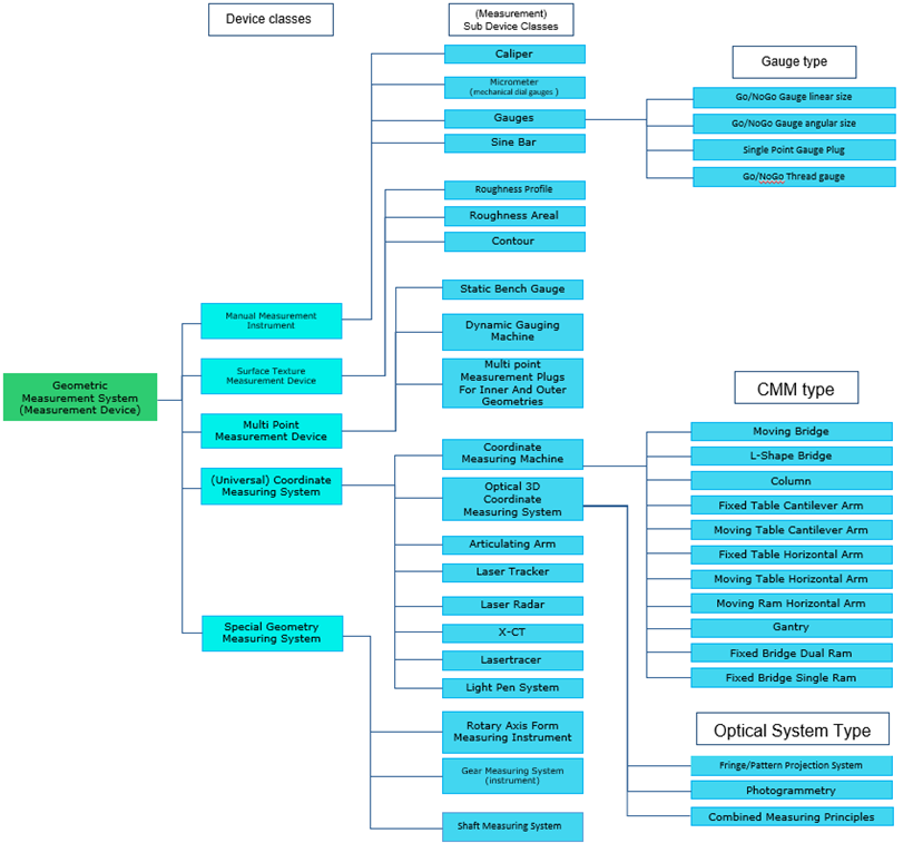
Figure 3 – Classification of GMS used in this Companion Specification
The output of all measurement systems are measurement results. For geometric measurement results, many file formats and structures (e.g., AQDEF® [AQDEF 5], DMIS [ISO 22093], QIF, I++ DMS, ...) and other generic formats (CSV, raw text, JSON, XML …) are used. All these formats have their specific use cases, domains, and benefits [Pfeifer 2006]. Therefore, this Companion Specification defines only the transport and the management of the result. The concepts of the result management are based on the Result Management of the OPC 40001-101.