5.5 ConnectsTo and ConnectsToParent ReferenceTypes
The ConnectsTo ReferenceType is a concrete ReferenceType used to indicate that source and target Node have a topological connection. It is NonHierarchical and symmetric, because this is natural for this Reference. The ConnectsTo Reference exists between a Network and the connected Devices (or their ConnectionPoint, respectively). Browsing a Network returns the connected Devices; browsing from a Device, one can follow the ConnectsTo Reference from the Device's ConnectionPoint to the Network.
The ConnectsToParent ReferenceType is a concrete ReferenceType used to define the parent (i.e. the communication Device) of a Network. It is a subtype of the ConnectsTo ReferenceType.
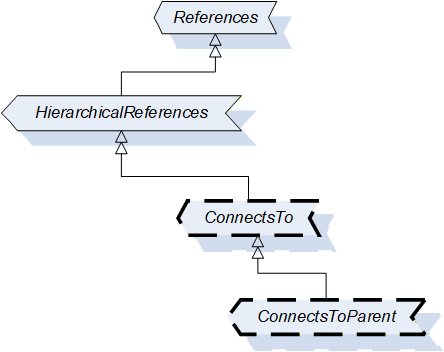
The two ReferenceTypes are illustrated in Figure 23.
The representation in the AddressSpace is specified in Table 48 and Table 49.
| Attributes | Value | ||
| BrowseName | 1:ConnectsTo | ||
| Symmetric | True | ||
| IsAbstract | False | ||
| References | NodeClass | BrowseName | Comment |
|---|---|---|---|
| Subtype of 0:NonHierarchicalReferences ReferenceType defined in OPC 10000-5. | |||
| Conformance Units | |||
| DI ConnectsTo | |||
| Attributes | Value | ||
| BrowseName | 1:ConnectsToParent | ||
| Symmetric | True | ||
| IsAbstract | False | ||
| References | NodeClass | BrowseName | Comment |
|---|---|---|---|
| Subtype of 1:ConnectsTo ReferenceType | |||
| Conformance Units | |||
| DI ConnectsTo | |||
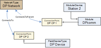
Figure 24 illustrates how this Reference can be used to express topological relationships and parental relationships. In this example two Devices are connected; the module DPcomm is the communication Device for the Network.