This section introduces the “OPC UA Information Model for Compressed Air Systems – Main Control System”.
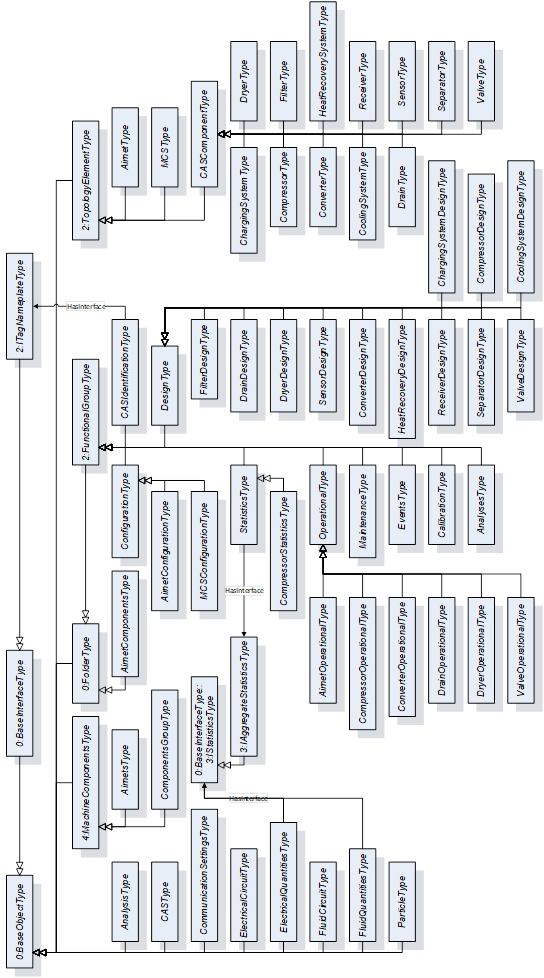
Figure 7 shows all ObjectTypes which are defined by this companion specification.

In most cases Variables have the TypeDefinition DataItemType or one of its subtypes. The optional Property Definition can be added to a Variable that uses such a TypeDefinition. This allows manufacturers to store a specific definition for each Variable.
Variables that use the DataType Boolean are modeled with the TypeDefinition TwoStateDiscreteType. Such Variables have the TrueState and FalseState Properties, which provide human readable and mandatory True and False states in their Value Attribute.
When applicable, the BrowseName of a FunctionalGroup was taken from the recommendation in OPC 10000-100.
A FunctionalGroup that would have no Variables, Objects, or Methods if instantiated shall not be instantiated.
Machines or systems downstream the Compressed Air System that use the compressed air require data on the condition of the compressed air. These conditions are provided at one or more Customer Distribution Points, depending on the concrete Compressed Air System setup. When modeling a Compressed Air System, the Customer Distribution Points shall be described as such. This can be done using external documentation, but it is recommended to use the Description Attribute of the Node that serves as the output of the Compressed Air System. Common examples of Customer Distribution Points are presented in chapter 6.3 Airnet Examples.
Figure 8 shows a simple model of an Airnet. The inlet of the Airnet is the sum of the inlets of compressors C1 and C2. The outlet of the Airnet is the Customer Distribution Point. All CASParts that are inside the red box are connected to the red Airnet and treated as such. The Main Control System is not a part of the Airnet.
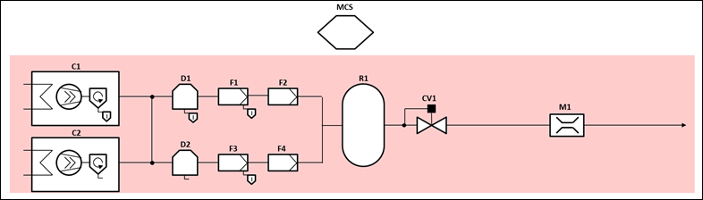
Figure 9 shows a Compressed Air System with two separate Airnets. The inlet of the red (upper) Airnet is the sum of the inlets of compressors C1 and C2. The outlet of the red Airnet is the upper Customer Distribution Point. All CASParts that are inside the red box are connected to the red Airnet and treated as such. The inlet of the blue (lower) Airnet is the sum of the inlets of compressors C3 and C4. The outlet of the blue Airnet is the lower Customer Distribution Point. All CASParts that are inside the blue box are connected to the blue Airnet and treated as such. The Main Control System is not a part of any Airnet.
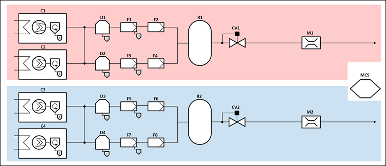
Figure 10 shows an arbitrary example on how two Airnets of the same Compressed Air System can be connected. The inlet of the red (bigger) Airnet is the sum of compressors C1, C2, C3, and C4. The two outlets of the red Airnet are the inlet of the dryer D3 and the lower Customer Distribution Point. All CASParts that are inside the red box are connected to the red Airnet and treated as such. The inlet of the blue (smaller) Airnet is the inlet of the dryer D3. The outlet of the blue Airnet is the upper Customer Distribution Point. All CASParts that are inside the blue box are connected to the blue Airnet and treated as such. The Main Control System is not a part of any Airnet.
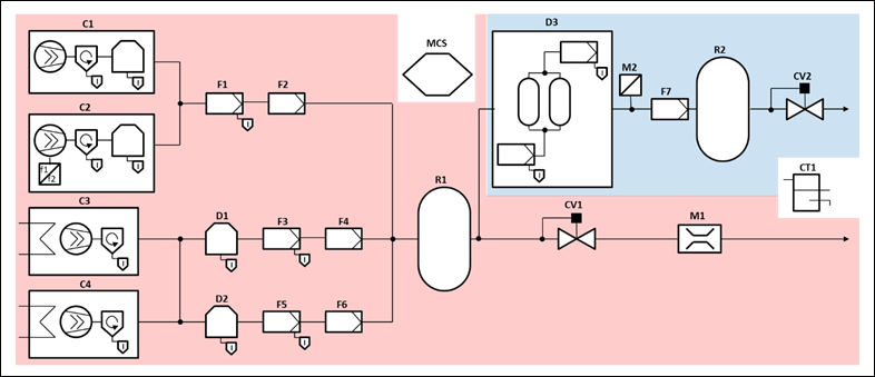
Figure 11 shows two overlapping Airnets of the same Compressed Air System. The inlet of the red (upper) Airnet is the sum of compressors C1 and C2. The two outlets of the red Airnet are the upper and the lower Customer Distribution Points. All CASParts that are inside the red box are connected to the red Airnet and treated as such. The inlet of the blue (lower) Airnet is the sum of compressors C3 and C4. The outlet of the blue Airnet is the lower Customer Distribution Point. All CASParts that are inside the blue box are connected to the blue Airnet and treated as such. The sensor M2 is connected to both Airnets. If Valve CV3 is open, the red Airnet is the active Airnet for M2. If Valve CV3 is closed, the blue Airnet is the active Airnet for M2. Valve CV3 is connected to the red Airnet and not to the blue Airnet, because its purpose is to divert the air from the Airnet with the higher pressure (red, 11 bar) to the lower distribution point and not from the Airnet with the lower pressure (blue, 8 bar) to the upper distribution point. The Main Control System is not a part of any Airnet.
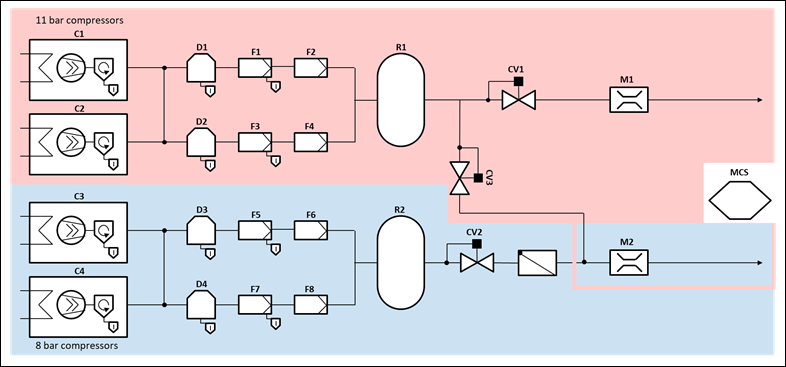
Figure 11 – Overlapping Airnets
The Compressed Air System and Airnets are identified by an Identification Object of the CASIdentificationType which uses the Interface ITagNameplateType and its Properties.
The Main Control System is identified by an Identification Object of the MachineryComponentIdentificationType.
Components are identified by an Identification Object of a subtype of the abstract MachineryItemIdentificationType defined by OPC UA for Machinery (OPC 40001-1). The MachineryItemIdentificationType and its subtypes provide the capabilities to globally uniquely identify the Component and have access to vendor defined information about the Component and manage user-specific information for the identification of the Component. When instantiating a Component, the Identification Object must use an appropriate subtype of the MachineryItemIdentificationType.
For all Components and the Main Control System the DeviceClass Property has its Value Attribute set to a mandatory specific value and its ModellingRule changed to mandatory.
Table 9 shows for each CASPart what value shall be set for different applications like the DeviceClass, BrowseName and GroupName.
Table 9 – DeviceClass, BrowseName and GroupName for CASParts
|
CASPart Name |
DeviceClass |
BrowseName |
GroupName |
|
Airnet |
- |
Airnet |
Airnets |
|
Charging System |
Charging system |
ChargingSystem |
ChargingSystems |
|
Compressor |
Compressor |
Compressor |
Compressors |
|
Condensate Drain |
Condensate drain |
CondensateDrain |
CondensateDrains |
|
Condensate Separator |
Condensate separator |
CondensateSeparator |
CondensateSeparators |
|
Converter |
Converter |
Converter |
Converters |
|
Cooling System |
Cooling system |
CoolingSystem |
CoolingSystems |
|
Dryer |
Dryer |
Dryer |
Dryers |
|
Filter |
Filter |
Filter |
Filters |
|
Heat Recovery System |
Heat recovery system |
HeatRecoverySystem |
HeatRecoverySystems |
|
Main Control System |
MCS |
MCS |
- |
|
Receiver |
Receiver |
Receiver |
Receivers |
|
Sensor |
Sensor |
Sensor |
Sensors |
|
Valve |
Valve |
Valve |
Valves |
For Components that are not defined by this specification, the DeviceClass Property shall be mandatory as well. The value shall match the name of the new Component.
All properties of the MachineryItemIdentificationType and its subtypes shall be used as intended by the OPC UA for Machinery (OPC 40001-1) specification.
To comply with the Finding all Machines in a Server use case of the OPC UA for Machinery (OPC 40001-1) specification, all Components that are considered as machines by their manufacturer or the customer shall be added to the Machines Object defined in OPC 40001-1 and use the MachineIdentificationType as TypeDefinition for their Identification Object. The Compressed Air System, the Main Control System, and Airnets are not considered as machine in the sense of OPC 40001-1, whereas the following Components may be considered as machines in this context (this list is not exhaustive):
- Compressors
- Converters
- Dryers
The manufacturer or system integrator of a Compressed Air System may wish to add Variables, Objects, or Methods which are not yet defined by this specification. In such a case the additional Variables, Objects, or Methods shall be added to an appropriate FunctionalGroup of the Component. It is important, that the Variables, Objects, or Methods which are added match the description of the FunctionalGroup they are added to. If there is no FunctionalGroup available the Variables, Objects, and Methods fit in, the manufacturer or system integrator shall create a new Object of the FunctionalGroupType.
It is also possible to define a subtype of the FunctionalGroupType or one of its subtypes to define a new collection of Variables, Objects, or Methods. When subtyping, the manufacturer or system integrator should keep in mind, that all Variables, Objects, and Methods of the supertype are also available to the new subtype.
In general, no new Variables, Objects, or Methods shall be created that are already available in this specification. If the manufacturer or system integrator wants to add already existing Variables, Objects, or Methods to another FunctionalGroup, the Organizes ReferenceType shall be used.
When creating Variables which are representing Quantities, the BaseAnalogType or one of its subtypes shall be used as TypeDefinition. When creating Variable which are not representing Quantities, the DataItemType or one of its subtypes, other than the BaseAnalogType, shall be used as TypeDefinition. Either way, the Definition Property shall be instantiated to further clarify the intended purpose of the Variable.
Figure 12 illustrates some usage examples on how to extend FunctionalGroups of a compressor.
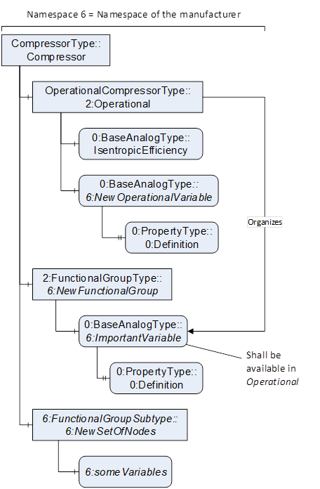
Figure 12 – Extending FunctionalGroups
Most CASParts have an optional FunctionalGroup with the default BrowseName Events. This FunctionalGroup provides Objects for common alarms and conditions. In total four conditions are defined: EmergencyStop, Service, Shutdown, and Warning. An OptionalPlaceholder Object <Event> with the TypeDefinition ConditionType is defined. If a manufacturer or system integrator adds additional alarms or conditions to a CASPart, <Event> shall be used. When instantiating <Event>, a concrete subtypes of the abstract ConditionType has to be used as TypeDefinition. To comply with Annex B of OPC 10000-9 – Part 9: Alarms and Conditions, a CASPart must have a HasCondition reference for each instantiated condition using the condition instance as TargetNode and the CASPart as SourceNode.
A manufacturer or system integrator may add custom alarms and conditions targeting specific Variables or Objects of a CASPart. In that case, the Variable or Object is the SourceNode and the condition instance is the TargetNode. If such an alarm or condition is created, the CASPart shall have a HasEventSource reference with the CASPart as SourceNode and the Variable or Object as TargetNode.
EXAMPLEA high limit alarm is needed for the Temperature Quantity at the process fluid inlet of a dryer. The Object InletTemperatureHighLimitAlarm using the ExclusiveLimitAlarmType as TypeDefinition is created as child of the Events Object of the dryer instance. A HasCondition reference is created with the Temperature Quantity as SourceNode and the InletTemperatureHighLimitAlarm as TargetNode. The dryer receives a HasEventSource reference to the Temperature Quantity.
To further comply with Annex B of OPC 10000-9, the Compressed Air System Object shall be the TargetNode of a HasNotifier reference, originating at the OPC UA Server Object. The Compressed Air System Object shall have a HasNotifier reference for each CASPart which instantiates alarms or conditions.
Every instantiated Component shall have at least one appropriate GeneratesEvent reference targeting the NAMUR NE 107 alarms defined in OPC 10000-100. These are CheckFunctionAlarmType, FailureAlarmType, MaintenanceRequiredAlarmType, and OffSpecAlarmType.
As defined by OPC 10000-5, all events shall have a severity assigned to them. This specification specifies specific severity ranges for some events. If no specific severity or severity range is provided for a defined event or condition, the manufacturer or integrator may choose from the default OPC UA range. The chosen severity when assigning it to a condition or event shall match the following categorization.
Table 10 – Severity Categorization
|
Severity |
Lower limit |
Upper limit |
|
HIGH |
801 |
1000 |
|
MEDIUM HIGH |
601 |
800 |
|
MEDIUM |
401 |
600 |
|
MEDIUM LOW |
201 |
400 |
|
LOW |
1 |
200 |
Figure 13 shows examples on how alarms and conditions shall be used in a Compressed Air System.
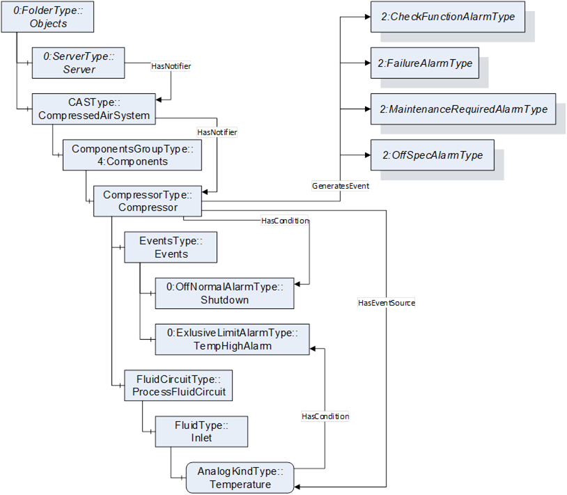
Figure 13 – Alarms and Conditions
All Component ObjectTypes in this specification (clauses 7.8 – 7.19) may be used for subtyping when defining more specific Components. If future companion specifications, a manufacturer, or system integrator wants to define a more specific ObjectType for one of the existing Components, the ObjectType of that Component shall be used as supertype.
If future companion specifications, a manufacturer, or system integrator wants to define a new Component which is not yet provided by this specification and which is no subtype of one of the existing Components, the CASComponentType shall be used as SourceNode for the new ObjectType.
If a manufacturer or system integrator wants to add a Component which is not yet defined by this specification and does not want to create a new ObjectType, the CASComponentType may be used as TypeDefinition for that Component. In such a case, the DataType of Design_ComponentClass must be changed to a concrete DataType.
Either way, in most cases a new Enumeration DataType is required to specify which ComponentClasses are possible for the new Component. The DataType shall be provided by the same party that introduces the new ObjectType.
Figure 14 shows all three approaches described above that a manufacturer or system integrator can take. The left panel shows the introduction of the new compressor type TurboCompressorType in a separate Namespace. The middle panel shows the introduction of a completely new Component type in a separate Namespace. The right panel shows the use of the CASComponentType as TypeDefinition for a new Component in a separate namespace. For each approach, the corresponding new enumeration is shown below.
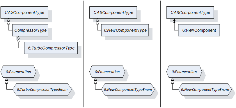
Figure 14 – Adding New Component Types
This document was created in parallel with the asset administration shell for Compressed Air Systems – Main Control System.
The organization Plattform Industrie 4.0 published the specification Details of the Asset Administration Shell to define the concept and metamodel for asset administration shells. The specification describes every aspect of asset administration shells in detail.
Figure 15 shows an abstract example on the composition of an I4.0 component and the content of an asset administration shell.
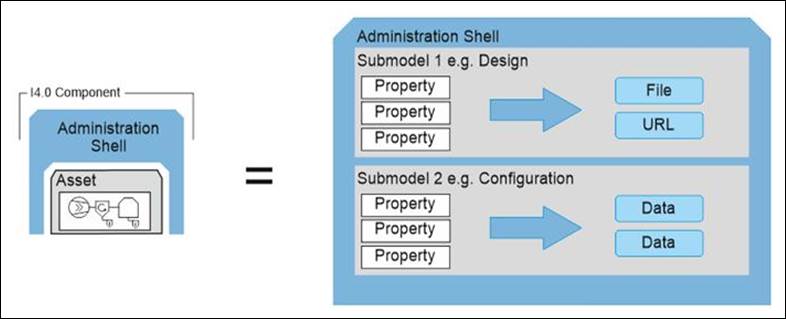
Figure 15 – I4.0 Component Consisting of Asset and Administration Shell
An asset administration shell is defined by the Plattform Industrie 4.0 organization as a “standardized digital representation of the asset, corner stone of the interoperability between the applications managing the manufacturing systems. It identifies the Administration Shell and the assets represented by it, holds digital models of various aspects (submodels) and describes technical functionality exposed by the Administration Shell or respective assets.”
The content of an asset administration shell consists of submodels and properties. “Each submodel refers to a well-defined domain or subject matter. Submodels can become standardized and thus become submodels templates.”
The content of this OPC UA Companion Specification is linked to the asset administration shell for Compressed Air Systems – Main Control Systems in a specific way. In general, submodels are modeled as subtypes of the FunctionalGroupType of OPC 10000-100.