Analyser types which fall under the category of particle size monitor devices can extend the ADI model further by defining Parameters and/or subtypes of ParticleSizeMonitorDeviceType, AccessoryType, AnalyserChannelType or StreamType.
In the simplest case, no subtypes need to be defined and the Parameters can be exposed on existing ParticleSizeMonitorDeviceType Object or one of its components.
The following is an example of how a particle size monitoring device could extend the ADI Information Model by further refining definition of an Accessory and by defining new Parameters on ParticleSizeMonitorType.
AnalyserChannelType defines two mandatory FunctionalGroups described in 5.2.2.1: Configuration and Status. StreamType defines seven mandatory FunctionalGroups described in 5.2.3.1: Configuration, Status, AcquistionSettings, AcquisitionStatus, AcquisitionData, ChemometricModelSettings, and Context. The following tables describe example sets of Parameters that can be defined on the AnalyserChannel and Stream of a ParticleSizeMonitorDevice, in this case using Laser Diffraction technology.
Table 93 – ParticleSizeMonitorDeviceType AnalyserChannel Configuration Parameters (Laser Diffraction Technology)
|
BrowseName |
Description |
VariableType |
Optional/ Mandatory |
|
DetectorCount |
Number of detectors |
DataItemType (DataType=Short) |
O |
Table 94 – ParticleSizeMonitorDeviceType AnalyserChannel Status Parameters (Laser Diffraction Technology)
|
BrowseName |
Description |
VariableType |
Optional/ Mandatory |
|
InstrumentConnected |
Return the status of the physical connection with the channel |
TwoStateDiscreteType (DataType=Boolean) |
O |
|
IsDetectorConnected |
Return the status of the physical connection with the detector |
TwoStateDiscreteType (DataType=Boolean) |
O |
|
IsLaserConnected |
Return the status of the physical connection with the laser |
TwoStateDiscreteType (DataType=Boolean) |
O |
|
IsLaserOn |
Return the status of Laser (On/Off) |
TwoStateDiscreteType (DataType=Boolean) |
O |
All Parameters organized by the Status FunctionalGroup on an AnalyserChannel of a ParticleSizeMonitorDeviceType shall be read-only.
Table 95 – ParticleSizeMonitorDeviceStreamType AcquisitionSettings Parameters (Laser Diffraction Technology)
|
BrowseName |
Description |
VariableType |
Optional/ Mandatory |
|
ParticleRI |
Particle Refractive Index |
DataItemType (DataType=RefractiveIndexType) |
O |
|
DispersantRI |
Dispersant Refractive Index (Air, Water, Ethanol …) |
DataItemType (DataType=RefractiveIndexType) |
O |
|
Density |
Material density . (Kg/m3) |
AnalogItemType (DataType=Double) |
O |
|
LowestDetector |
Lowest detector enabled for acquisition |
AnalogItemType (DataType=Short) |
O |
|
HighestDetector |
Highest detector enabled for acquisition |
AnalogItemType (DataType=Short) |
O |
|
Threshold |
Minimum signal required for getting data |
AnalogItemType (DataType=Double) |
O |
|
Gain |
Detector gain |
AnalogItemType (DataType=Double) |
O |
|
AnalysisType |
Type of analysis. (Vendor Specific) |
MultiStateDiscreteType (Vendor specific enumeration) |
O |
|
DistributionSizeLow |
Minimum Size definition |
AnalogItemType (DataType=Double) |
O |
|
DistributionSizeHigh |
Maximum Size definition |
AnalogItemType (DataType=Double) |
O |
|
DistributionChannelCount |
Number of channel |
AnalogItemType (DataType=Double) |
O |
|
ContinuousMode |
Define the acquisition mode : Continuous Measurement Discontinuous Measurement |
TwoStateDiscreteType (DataType=Boolean) |
O |
|
UpdatePeriod |
In Continuous mode this is the period the analyser will produce a result |
AnalogItemType (DataType=Float) |
O |
|
MeasurementDuration |
In discontinuous mode this is the acquisition time |
AnalogItemType (DataType=Float) |
O |
|
BackgroundDuration |
Background measurement duration |
AnalogItemType (DataType=Float) |
O |
As an alternative to chapter A.2.1, the tables below show a more general approach of defining the Parameters, independent of the used technology.
Table 96 – ParticleSizeMonitorDeviceType AnalyserChannel Status Parameters (Alternative to Table 94)
|
BrowseName |
Description |
VariableType |
RW |
Optional/ Mandatory |
|
InstrumentConnected |
Return the status of the physical connection with the channel |
TwoStateDiscreteType (DataType=Boolean) |
RO |
O |
|
ReadyForBackground |
Return the status of the instrument and accessories to perform a background reading |
TwoStateDiscreteType (DataType=Boolean) |
RO |
O |
|
ReadyForMeasurement |
Return the status of the instrument and accessories to perform a measurement |
TwoStateDiscreteType (DataType=Boolean) |
RO |
O |
All Parameters organized by the Status FunctionalGroup on an AnalyserChannel of a ParticleSizeMonitorDeviceType shall be read-only.
Table 97 – ParticleSizeMonitorDeviceStreamType AcquisitionSettings Parameters(Alternative to Table 95)
|
BrowseName |
Description |
VariableType |
Optional/ Mandatory |
|
AcquisitionSettings |
Name of a set of acquisition settings stored in the analyser. |
M |
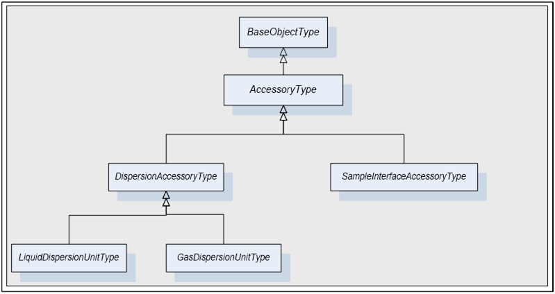
Figure 22 - AccessoryType of ParticleSizeMonitorDeviceType
DispersionAccessoryType is a subtype of AccessoryType. A dispersion unit allows dispersing powder. A dispersant is a liquid or gas added to a mixture to promote dispersion or to maintain dispersed particles in suspension.
LiquidDispersionUnitType is a subtype of DispersionAccessory. A liquid dispersion unit is a unit dispersing a mixture using a liquid (Water, ethanol …)
GasDispersionUnitType is a subtype of DispersionAccessory. A gas dispersion unit is a unit dispersing a mixture using a gas (Air, Nitrogen …)
SampleInterfaceAccessoryType is a subtype of AccessoryType. A sample interface is a unit allowing sample from the process line in order to perform a measurement. A sample interface accessory could be an auger, a rotational sampler, a simple probe, etc …
Table 98 - DispersionAccessoryType
|
Attribute |
Value |
|||||
|
BrowseName |
DispersionAccessoryType |
|||||
|
IsAbstract |
true |
|||||
|
References |
NodeClass |
BrowseName |
DataType |
TypeDefinition |
ModellingRule |
|
|
Subtype of the AccessoryType defined in 5.2.5.1 |
||||||
|
HasSubtype |
ObjectType |
LiquidDispersionUnitType |
|
|||
|
HasSubtype |
ObjectType |
GasDispersionUnitType |
|
|||
All DispersionAccessoryType have Attributes and Properties that they inherit from the AccessoryType. In addition to those, it is possible to define more Parameters.
DispersionAccessoryType can have, for example, the following Parameters defined.
Table 99 – DispersionAccessoryType Configuration Parameters
|
BrowseName |
Description |
VariableType |
Optional/ Mandatory |
|
DisperionSettings |
Name of a set of dispersion settings stored in the analyser. |
M |
Table 100 – DispersionAccessoryType Status Parameters
|
BrowseName |
Description |
VariableType |
Optional/ Mandatory |
|
Mode |
Accessory mode |
MultiStateDiscreteType
|
O |
All Parameters organized by the Status FunctionalGroup on a DispersionAccessoryType shall be read-only.
Subtypes of DispersionAccessoryType are optional. The definitions below serve as an example for Laser Diffraction or Image Analysers. Other technologies might require other definitions or none at all.
Table 101 - LiquidDispersionUnitType
|
Attribute |
Value |
|||||
|
BrowseName |
LiquidDispersionUnitType |
|||||
|
IsAbstract |
False |
|||||
|
References |
NodeClass |
BrowseName |
DataType |
TypeDefinition |
ModellingRule |
|
|
Subtype of the DispersionAccessoryType defined in A.3.1. |
||||||
|
|
|
|
|
|
|
|
This Object defines an instance of the LiquidDispersionUnitType as defined in.
LiquidDispersionUnitType has the following Parameters defined.
Table 102 – LiquidDispersionUnitType Configuration Parameters
|
BrowseName |
Description |
VariableType |
Optional/ Mandatory |
|
PumpSpeed |
Pump Speed allowing transporting the sample to the analyser |
AnalogItemType (DataType=Double) |
O |
|
StirrerSpeed |
Stirrer Speed allowing mixing sample and dispersant |
AnalogItemType (DataType=Double) |
O |
|
Ultrasonic |
Ultrasonic power allowing breaking agglomerate |
AnalogItemType (DataType=Double) |
O |
|
UltrasonicMode |
Apply ultrasonic continuously or periodically . (may be more option |
MultiStateDiscreteType (Vendor specific enumeration) |
O |
|
UltrasonicTimeOn |
Time the ultrasonic has to be ON |
AnalogItemType (DataType=Double) |
O |
|
UltrasonicTimeOff |
Time the ultrasonic has to be OFF |
AnalogItemType (DataType=Double) |
O |
Table 103 – LiquidDispersionUnitType Status Parameters
|
BrowseName |
Description |
VariableType |
Optional/ Mandatory |
|
Mode |
Accessory mode |
MultiStateDiscreteType
|
O |
All Parameters organized by the Status FunctionalGroup on a LiquidDispersionUnitType shall be read-only.
Table 104 – GasDispersionUnitType Object
|
Attribute |
Value |
|||||
|
BrowseName |
GasDispersionUnitType |
|||||
|
IsAbstract |
False |
|||||
|
References |
NodeClass |
BrowseName |
DataType |
TypeDefinition |
ModellingRule |
|
|
Subtype of the DispersionAccessoryType defined in A.3.1 |
||||||
|
|
|
|
|
|
|
|
This Object defines an instance of the GasDispersionUnitType Object as defined in Table 104
GasDispersionUnitType has the following Parameters defined.
Table 105 – GasDispersionUnitType Configuration Parameters
|
BrowseName |
Description |
VariableType |
Optional/ Mandatory |
|
Pressure |
Pressure allowing dispersion |
AnalogItemType (DataType=Double) |
O |
|
Flow |
Gas flow for dispersing |
AnalogItemType (DataType=Double) |
O |
|
FeedRate |
Vibration Feeder |
AnalogItemType (DataType=Double) |
O |
Table 106 - GasDispersionUnitType Status Parameters
|
BrowseName |
Description |
VariableType |
Optional/ Mandatory |
|
Mode |
Accessory mode |
MultiStateDiscreteType
|
O |
All Parameters organized by the Status FunctionalGroup on a GasDispersionUnitType shall be read-only.
(informative) – Example of extending ADI Information Model for gas chromatograph devices
Analyser types which fall under the category of gas chromatographs (GC) can extend the ADI model further by defining Parameters and/or subtypes of ChromatographDeviceType, Accessory, AnalyserChannel and/or Stream.
In the simplest case, no subtypes of ChromatographDeviceType need to be defined and the Parameters can be exposed on existing ChromatographDeviceType Object or one of its components.
The following paragraphs provide an example of how a gas chromatograph device could extend the ADI Information Model by further refining definition of an Accessory and by defining new Parameters on ChromatographDeviceType.
The Figure 23 shows how a typical GC works:
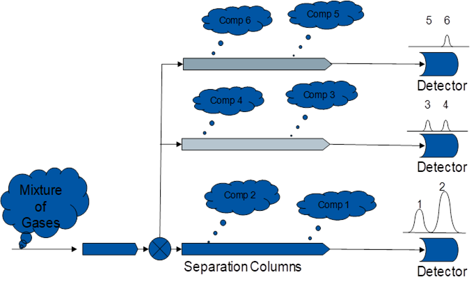
- The sample is extracted from the process using a sampling system external to the GC itself. It is done in a way that minimizes the time between the sample extraction from the process and its injection into the separation column sets.
- Each separation column set is maintained at a precise temperature by an oven, and used to separate molecules of the sample based on their size and chemical Properties.
- The propagation time through a given set of columns for a given component, is based on its size and Properties and the column Properties.
- The detector at the end of a column set monitors the outlet stream from the column; It determines the amount of a given component at the outlet and the time it used to reach it. The resulting detector output is a XY plot of the detector level versus time, called chromatogram.
- A set of mathematical algorithms converts the chromatogram peaks into component concentration.
The example set of Parameters defined on a ChromatographDeviceType for a gas chromatograph are described in Table 107 and Table 108.
Table 107- ChromatographDeviceType Configuration Parameters
|
BrowseName |
Description |
VariableType |
Optional/ Mandatory |
|
SetTime |
SetTime is a Write only, Ole Date tag that is used to set the device and/or system time. If an analyser can be configured as a time server, the SetTime tag is used to update the time/date in that time server. The other devices in the system must be configured with the IP address of the designated time server. |
DataItemType (DataType=DateTime) |
O |
Table 108 - ChromatographDeviceType Status Parameters
|
BrowseName |
Description |
VariableType |
Optional/ Mandatory |
|
ComState |
The ComState tag is a read-only, 4-byte integer value that displays the current status of the communication link between the remote computer and the device. |
DataItemType (DataType=Int32) |
O |
All Parameters organized by the Status FunctionalGroup on a ChromatographDeviceType shall be read-only.
The example set of Parameters defined on an AnalyserChannel of ChromatographDeviceType for a gas chromatograph are described in Table 109.
Table 109 - ChromatographDeviceType AnalyserChannel Configuration Parameters
|
BrowseName |
Description |
VariableType |
Optional/ Mandatory |
|
RunState |
Sets the state of the chromatographic application. 0 = This application is in HOLD 1 = This application is in the RUN state 2 = This application is in the CALibration state 3 = This application is in the VALidation state Other values are not allowed. Write format: range 0 - 3 0 = Sets application to HOLD state 1 = Sets application to RUN state 2 = Sets application to CAL state 3 = Sets application to VAL state |
O |
The example set of Parameters defined on a ChromatographDeviceStreamType for a gas chromatograph are described in Table 110.
Table 110 - ChromatographDeviceStreamType Configuration Parameters
|
BrowseName |
Description |
VariableType |
Optional/ Mandatory |
|
RunEvent |
RunEvent is a read/write, 4-byte integer used to run a stream dependent event. |
DataItemType (DataType=Int32) |
O |
|
SetAlarm |
SetAlarm is a read/write, 4-byte integer that is used to set an alarm in the device. |
DataItemType (DataType=Int32) |
O |
The concentration of a given Component and its related characteristics are represented using a Parameter of a type derived from EngineeringValueType.
The Value DataType is Float and its ValueRank is -1 because it is a scalar.
All components of this Variable are read-only.
Table 111 and Table 112 illustrate two example definitions of types that represent gas chromatograph Components.
Table 111 - ABBComponentValueType definition
|
Attribute |
Value |
|||||
|
BrowseName |
ABBComponentValueType |
|||||
|
IsAbstract |
False |
|||||
|
References |
NodeClass |
BrowseName |
Description |
TypeDefinition |
ModellingRule |
|
|
Subtype of the EngineeringValueType |
||||||
|
HasComponent |
Variable |
AmplitudeEOB |
Detector signal amplitude for the end of baseline calculation |
AnalogItemType (DataType=Float) |
Mandatory |
|
|
HasComponent |
Variable |
AmplitudeEOI |
Detector signal amplitude for the end of integration calculation |
AnalogItemType (DataType=Float) |
Mandatory |
|
|
HasComponent |
Variable |
AmplitudeSOB |
Detector signal amplitude for the start of baseline calculation |
AnalogItemType (DataType=Float) |
Mandatory |
|
|
HasComponent |
Variable |
AmplitudeSOI |
Detector signal amplitude for the start of integration calculation |
AnalogItemType (DataType=Float) |
Mandatory |
|
|
HasComponent |
Variable |
BaselineEnd |
Time into analysis of end of baseline calculation |
AnalogItemType (DataType=Float) |
Mandatory |
|
|
HasComponent |
Variable |
BaselineStart |
Time into analysis of start of baseline calculation |
AnalogItemType (DataType=Float) |
Mandatory |
|
|
HasComponent |
Variable |
BenchmarkDeviation |
This component’s deviation from defined validation concentration |
AnalogItemType (DataType=Float) |
Mandatory |
|
|
HasComponent |
Variable |
CrestAmplitude |
Maximum peak height for this component |
AnalogItemType (DataType=Float) |
Mandatory |
|
|
HasComponent |
Variable |
ExpectedConcentration |
This component’s expected concentration result from a validation analysis |
AnalogItemType (DataType=Float) |
Mandatory |
|
|
HasComponent |
Variable |
ExpectedRT |
This component’s expected retention time for a given analysis |
AnalogItemType (DataType=Float) |
Mandatory |
|
|
HasComponent |
Variable |
IntegrationEnd |
Time into analysis of end of integration calculation |
AnalogItemType (DataType=Float) |
Mandatory |
|
|
HasComponent |
Variable |
IntegrationStart |
Time into analysis of start of integration calculation |
AnalogItemType (DataType=Float) |
Mandatory |
|
|
HasComponent |
Variable |
IsValid |
Validity flag for this component |
TwoStateDiscreteType (DataType=Boolean) |
Mandatory |
|
|
HasComponent |
Variable |
NegativeArea |
Negative peak area for this component |
AnalogItemType (DataType=Float) |
Mandatory |
|
|
HasComponent |
Variable |
OldResponseFactor |
Previous calibration response factor for this component |
AnalogItemType (DataType=Float) |
Mandatory |
|
|
HasComponent |
Variable |
PeakFound |
Flag for a peak detected |
TwoStateDiscreteType (DataType=Boolean) |
Mandatory |
|
|
HasComponent |
Variable |
PositiveArea |
Positive peak area for this component |
AnalogItemType (DataType=Float) |
Mandatory |
|
|
HasComponent |
Variable |
ResponseFactor |
Calibration response factor for this component and associated detector |
AnalogItemType (DataType=Float) |
Mandatory |
|
|
HasComponent |
Variable |
Retention Time |
Actual retention time at the peak apex for this component |
AnalogItemType (DataType=Float) |
Mandatory |
|
|
HasComponent |
Variable |
RFUpdated |
Flag if the new RF from a calibration analysis is accepted |
TwoStateDiscreteType (DataType=Boolean) |
Mandatory |
|
|
HasComponent |
Variable |
TotalArea |
Total peak area for this component |
AnalogItemType (DataType=Float) |
Mandatory |
|
Table 112 – SiemensComponentValueType Definition
|
Attribute |
Value |
||||||||
|
BrowseName |
SiemensComponentValueType |
||||||||
|
IsAbstract |
False |
||||||||
|
References |
NodeClass |
BrowseName |
Description |
TypeDefinition |
ModellingRule |
||||
|
Subtype of the EngineeringValueType |
|||||||||
|
HasComponent |
Variable |
PkArea |
Corrected peak area for this component. |
AnalogItemType (DataType=Double) |
Mandatory |
||||
|
HasComponent |
Variable |
PkArea% |
Percent area for this component. |
AnalogItemType (DataType=Double) |
Mandatory |
||||
|
HasComponent |
Variable |
PkAsym |
Peak asymmetry for this component. |
AnalogItemType (DataType=Double) |
Mandatory |
||||
|
HasComponent |
Variable |
PkAsym10 |
Asymmetry at 10% peak height for |
AnalogItemType (DataType=Double) |
Mandatory |
||||
|
HasComponent |
Variable |
PkHeight |
Maximum peak height for this component. |
AnalogItemType (DataType=Double) |
Mandatory |
||||
|
HasComponent |
Variable |
PkHeight% |
Percent height for this component. |
AnalogItemType (DataType=Double) |
Mandatory |
||||
|
HasComponent |
Variable |
PkNoise |
Peak noise for this component. |
AnalogItemType (DataType=Double) |
Mandatory |
||||
|
HasComponent |
Variable |
PkResolution |
Peak resolution relative to previous peak for this component. |
AnalogItemType (DataType=Double) |
Mandatory |
||||
|
HasComponent |
Variable |
PkRetTime |
Retention time at peak apex for this component. |
AnalogItemType (DataType=Double) |
Mandatory |
||||
|
HasComponent |
Variable |
PkSignaltoNoise |
Peak signal to noise for this component. (Peak height / rms noise) |
AnalogItemType (DataType=Double) |
Mandatory |
||||
|
HasComponent |
Variable |
PkStartFlg |
Peak start flag for this component. |
AnalogItemType (DataType=String) |
Mandatory |
||||
|
HasComponent |
Variable |
PkStartTime |
Retention time at start of peak for this component. |
AnalogItemType (DataType=Double) |
Mandatory |
||||
|
HasComponent |
Variable |
PkStopFlg |
Peak stop flag for this component. |
AnalogItemType (DataType=Double) |
Mandatory |
||||
|
HasComponent |
Variable |
PkStopTime |
Retention time at end of peak for this component. |
AnalogItemType (DataType=Double) |
Mandatory |
||||
|
HasComponent |
Variable |
PkType |
Peak type this component. |
AnalogItemType (DataType=Double) |
Mandatory |
||||
|
HasComponent |
Variable |
PkUSPWidth |
Peak USP width (U.S. Pharmacopeia) for this component. |
AnalogItemType (DataType=Double) |
Mandatory |
||||
|
HasComponent |
Variable |
PkWidth |
Peak width at base for this component. |
AnalogItemType (DataType=Double) |
Mandatory |
||||
|
HasComponent |
Variable |
PkWidth10 |
Peak width at 10% height for this component. |
AnalogItemType (DataType=Double) |
Mandatory |
||||
|
HasComponent |
Variable |
PkWidth5% |
Peak width at 5% height for this component. |
AnalogItemType (DataType=Double) |
Mandatory |
||||
|
HasComponent |
Variable |
PkWidth50 |
Peak width at 50% height for this component. |
AnalogItemType (DataType=Double) |
Mandatory |
||||
|
HasComponent |
Variable |
PkTheorPlates |
Theoretical plates for this component. |
AnalogItemType (DataType=Double) |
Mandatory |
||||
|
HasComponent |
Variable |
GrpArea |
Corrected peak area (for the group) for this component. |
AnalogItemType (DataType=Double) |
Mandatory |
||||
|
HasComponent |
Variable |
GrpArea% |
Peak area percent (for the group) for this component. |
AnalogItemType (DataType=Double) |
Mandatory |
||||
|
HasComponent |
Variable |
GrpHeight |
Maximum peak height (for the group) for this component. |
AnalogItemType (DataType=Double) |
Mandatory |
||||
|
HasComponent |
Variable |
RespFactL0 |
Calibration level response factor for level 0 if applicable for this component. |
AnalogItemType (DataType=Double) |
Mandatory |
||||
|
HasComponent |
Variable |
RespFactL1 |
Calibration level response factor for level 1 if applicable for this component. |
AnalogItemType (DataType=Double) |
Mandatory |
||||
|
HasComponent |
Variable |
RespFactL2 |
Calibration level response factor for level 2 if applicable for this component. |
AnalogItemType (DataType=Double) |
Mandatory |
||||
|
HasComponent |
Variable |
RespFactL3 |
Calibration level response factor for level 3 if applicable for this component. |
AnalogItemType (DataType=Double) |
Mandatory |
||||
|
HasComponent |
Variable |
RespFactL4 |
Calibration level response factor for level 4 if applicable for this component. |
AnalogItemType (DataType=Double) |
Mandatory |
||||
|
HasComponent |
Variable |
RespFactL5 |
Calibration level response factor for level 5 if applicable for this component. |
AnalogItemType (DataType=Double) |
Mandatory |
||||
|
HasComponent |
Variable |
RespFactL6 |
Calibration level response factor for level 6 if applicable for this component. |
AnalogItemType (DataType=Double) |
Mandatory |
||||
|
HasComponent |
Variable |
RespFactL7 |
Calibration level response factor for level 7 if applicable for this component. |
AnalogItemType (DataType=Double) |
Mandatory |
||||
|
HasComponent |
Variable |
RespFactL8 |
Calibration level response factor for level 8 if applicable for this component. |
AnalogItemType (DataType=Double) |
Mandatory |
||||
|
HasComponent |
Variable |
RespFactL9 |
Calibration level response factor for level 9 if applicable for this component. |
AnalogItemType (DataType=Double) |
Mandatory |
||||
(informative) – Parameter Representation
Parameters which hold simple data like a single numerical value, string value or a time-stamp value are represented by BaseDataVariableType defined in [OPC 10000-5] or one of its subtypes.
Variables which hold simple data like a single numerical value, string value or a time-stamp value are represented by BaseDataVariableType defined in [OPC 10000-5]. Those Variables typically represent some configuration Parameters, status, states or acquisition results of an analyser.
If a Variable represents simple data which is obtained “live” from an analyser, DataItem VariableType or one of its subtypes will be used. For example, AnalogItemType shall be used when there is a need for a specific Property of the AnalogItemType such as EURange and EngineeringUnits [OPC 10000-8].
Table 72 describes how each Attribute of super/sub class of DataItem is used in the ADI context.
Table 113 - ADI DataItem Attributes
|
Attributes/Properties |
Description |
|
Base NodeClass |
|
|
DisplayName |
Localized user readable name of this DataItem |
|
BrowseName |
The programmatic name of this DataItem |
|
Description |
Localized user readable description |
|
WriteMask |
Supports access control implementation |
|
UserWriteMask |
Supports access control implementation |
|
Variable NodeClass |
|
|
Value |
The Parameter value itself |
|
DataType |
DataType of Value |
|
ValueRank |
The number of dimensions of value |
|
ArrayDimensions |
The size of each value dimensions |
|
AccessLevel |
Supports access control implementation of Value |
|
UserAccessLevel |
Supports access control implementation of Value |
|
MinimumSamplingInterval |
Defined how fast Value may be updated |
|
DataItemType |
|
|
Definition |
Vendor-specific, human readable string that specifies how the value of this DataItem is calculated. Definition is non-localized and will often contain an equation that can be parsed by certain Clients. Example Definition ::= “(TempA – 25) + TempB” |
|
ValuePrecision |
The maximum precision that the Server can maintain for the item based on restrictions in the target environment |
|
AnalogItemType |
|
|
InstrumentRange |
The value range that can be returned by the instrument |
|
EURange |
The value range likely to be obtained in normal operation. It is intended for such use as automatically scaling a bar graph display |
|
EngineeringUnits |
The units for the DataItem’s value (e.g., DEGC, hertz, seconds ) |
|
TwoStateDiscreteItemType |
|
|
TrueState |
String to be associated with this DataItem when it is TRUE. This is typically used for a contact when it is in the closed (non-zero) state. e.g. "RUN", "CLOSE", "ENABLE", "SAFE“, etc. |
|
FalseState |
String to be associated with this DataItem when it is FALSE. This is typically used for a contact when it is in the open (zero) state.e.g. "STOP", "OPEN", "DISABLE", "UNSAFE“, etc. |
|
MultiStateDiscreteItemType |
|
|
EnumStrings |
EnumStrings which is a string lookup table corresponding to sequential numeric values (0, 1, 2, etc.) Example: ”OPEN” ”CLOSE” ”IN TRANSIT” etc |
The other source of information is the OPC UA Read Service described in [OPC 10000-4]. It provides:
- The current value itself
- Quality of the value
- The time of the last update
The SemanticsChanged bit in StatusCode
Parameters which hold array data that may be acquired during normal analyser operation or used as inputs (e.g. background, calibration) are represented by VariableTypes which are direct subtypes of DataItemType.
They inherit all of the Properties of the DataItemType. Also, they inherit a set o Attributes from the Variable NodeClass that are common to all derived VariableTypes. Refer to Table 113 for more information.
The decision to base the array types on the DataItemType rather than the AnalogItemType is to allow a modification of the StatusCode.SemanticsChanged. In the AnalogItemType, this bit is set if and only if a change occurs in one or several of the Properties InstrumentRange, EURange and EngineeringUnits. In the ADI array types; this bit changes if and only if a change occurs in one or several of the Properties InstrumentRange, EURange, EngineeringUnits and the axis definitions. This also allows the implementation of the type where the Value.DataType is not a subclass of Number like in the XYArrayItemType.
To simplify the development of ADI Clients/Servers, the Properties InstrumentRange, EURange and EngineeringUnits, that are part of the AnalogItemType definition, are reused with exactly the same semantic as in the AnalogItemType:
InstrumentRange defines the value range that can be returned by the instrument.
Example: InstrumentRange ::= {-9999.9, 9999.9}
The Range type is specified in [OPC 10000-8].
EURange defines the value range likely to be obtained in normal operation. It is intended for such use as automatically scaling a bar graph display.
Sensor or instrument failure or deactivation can result in a returned item value which is actually outside this range. Client software must be prepared to deal with this. Similarly a Client may attempt to write a value that is outside this range back to the Server. The exact behaviour (accept, reject, clamp, etc.) in this case is Server-dependent. However in general Servers must be prepared to handle this.
Example: EURange ::= {-200.0,1400.0}
EngineeringUnits specifies the units for the DataItem’s value (e.g., DEGC, hertz, seconds).
The EUInformation type is specified in [OPC 10000-8].
If the item contains an array the Properties will apply to all elements in the array.
(informative) – Events, Alarms and Conditions
This specification does not introduce any standard types of Events, Alarms or Conditions.
Transitions defined as part of the AnalyserDeviceStateMachineType, OperatingStateMachineType, their subtypes and sub-states shall produce events which are subtypes of TransitionEventType defined in [OPC 10000-5].
(informative) – Operation level result codes
Table 114 provides additional ADI-specific guidelines for interpretation of the Uncertain operation level result code defined in [OPC 10000-8].
Table 114 - Uncertain operation level result codes
|
Symbolic Id |
Description |
|
Uncertain_ NoCommunicationLastUsable |
Communication to the data source has failed. The Variable value is the last value that had a good quality and it is uncertain whether this value is still current. The Server timestamp in this case is the last time that the communication status was checked. The time at which the value was last verified to be true is no longer available.
In ADI, this implies that the communication to the analyser has failed, but the Analyser Server is still active and communicating with its Clients. The Clients need updates, so the Server is responsible for maintaining the namespace and all the values. |
|
Uncertain_LastUsableValue |
Whatever was updating this value has stopped doing so. This happens when an input Variable is configured to receive its value from another Variable and this configuration is cleared after one or more values have been received. This status/substatus is not used to indicate that a value is stale. Stale data can be detected by the Client looking at the timestamps.
In ADI, this differs from the Uncertain_NoCommunicationLastUsable code only in that is does not explicitly state that there is no communication. For some undetermined reason, the analyser can no longer update the values. In the case of spectrographic analysers, there may be a significant error in the model that stops the collection and analysis (too many bad scans, divide by zero exception in the math model, etc.). |
|
Uncertain_SubstituteValue |
The value is an operational value that was manually overwritten. This value is a placeholder value that is set by the user when the instrument cannot collect or update the data. |
|
Uncertain_InitialValue |
The value is an initial value for a Variable that normally receives its value from another Variable. This status/substatus is set only during configuration while the Variable is not operational (while it is out-of-service). In ADI, this bit is set for all Variables when the configuration is first loaded and started. The initial value is a preconfigured value defined when the instrument is first configured. |
|
Uncertain_SensorNotAccurate |
The value is at one of the sensor limits. The Limits bits define which limit has been reached. Also set if the device can determine that the sensor has reduced accuracy (e.g. degraded analyser), in which case the Limits bits indicate that the value is not limited. In ADI, some internal diagnostic value in the analyser indicates that there is something inaccurate or untrustworthy in the data. For example, in FTIR, the interferogram peak center burst location or height may be beyond the acceptable threshold. Also, the internal temperature of the analyser may be out of specification. In both cases, spectra can be collected, but the accuracy of those spectra are in doubt. |
|
Uncertain_ EngineeringUnitsExceeded |
The value is outside of the range of values defined for this Parameter. The Limits bits indicate which limit has been reached or exceeded. In ADI, there are multiple contexts where this code is applicable. In the instrument, it is possible that the analyser sensor or detector is close to saturated or overexposed. The analyser hardware itself is almost incapable of measuring the physical system, and thus any results from the analyser are untrustworthy. For example, if the detector saturates at 32767 counts, any readings over 28000 counts can be deemed uncertain. These limits are vendor specific. Another example involves the mathematical modelling that occurs in the analysers. Analysers are typically calibrated and optimized to measure data and produce results in a particular range. If the inputs or calculated output exceeds that range, the validity of the mathematical calculations and results are uncertain. |
|
Uncertain_SubNormal |
The value is derived from multiple sources and has less than the required number of Good sources. In the analyser, the data may be an accumulation or an averaging of many measurements. If any of those measurements is uncertain or bad, then the data is subnormal. For example, spectra are typically a co-addition or an averaging of multiple scans of the system. It is possible that some, but not all of those scans, may be bad or unusable. A few unusable scans will not prevent the system from collecting and processing the data. However, the fact that some bad scans exist should not be ignored either. If the number of bad scans exceeds a vendor defined threshold, then the data is subnormal. |
(informative) – ADI address space
This annex is intended to provide some guidelines on how to design the address space of an Analyser Server. It covers the following topics:
- Main questions to answer before starting the address space design
- Configuration process
- Parameter definition
- OPC UA key elements
- General rules
This annex should be used as a check list of points to address during the design and the source of description of the rationale behind some elements of the ADI specification. The annex is written in the FAQ format.
This section describes the basic questions that must be answered before starting the address space design.
Is the number of AnalyserChannels constant for this analyser or does it change frequently? For example, the GC has the concept of software AnalyserChannel, and new AnalyserChannels may be added over the time.
Is the number of Streams per AnalyserChannel constant for this analyser or does it change frequently?
Does the analyzer have a default configuration that allows the user to start the analyser without loading a configuration? This is true for small dedicated analysers that have a single mode of operation. This can also be true if the last configuration is automatically recalled at analyser power-up.
Will the analyser continue to acquire data if the connection with the client is broken?
Does the analyser server implement access control?
What is the access control scheme: user id based, role based?
Does the analyser server expose the same Parameters to all users?
Knowing that this specification has been developed partly to support analyser deployment in the pharmaceutical industry, how do you plan to support 21 Part 11 regulations? This is not mandatory in the ADI specification, but a good practice to plan for it knowing that it does not require more development, but rather follow some basic design concepts.
How do you plan to do the internationalization of the text elements that can be translated?
What is your error handling philosophy?
How do you report error to the client: through status, events…?
What do you put in the audit log?
Do you support more than one model of analyzer with this analyser server?
Does this analyser server handle more than one analyze simultaneously?
This section addresses questions related to the analyser server configuration.
What is the analyser server configuration philosophy?
Offline configuration using vendor specific tool using a proprietary configuration format, then call SetConfiguration method. This approach is often cost effective in the short term, when migrating legacy analysers, but limits the benefits of the open ADI standard.
Offline configuration using vendor specific tool but using a public, documented configuration format. A documented XML format is a good example.
Start the analyser server and configure each Parameter manually using an OPC UA / ADI client.
Dual approach, which combines the offline configuration with public configuration format followed by a call to SetConfiguration. This can be followed with the client updating some Parameters before starting the acquisition process. This is the preferred approach because it allows the client to:
Use standard configuration templates and apply specific changes.
Use generic tools for configuration and deployment tasks
Update some Parameters live, which is very convenient during diagnostics.
This section helps define, initialise and position Parameters in the Analyser Server address space.
A configuration parameter defining one of the settings of the hardware of the analyser.
A configuration parameter defining one of the settings of the behaviour of the analyser.
A status parameter exposing the state / status of the hardware of the analyser i.e. power supply temperature.
A status parameter exposing the state / status of the behaviour of the analyser i.e. which Stream is active?
A configuration parameter defining one of the settings of the hardware of the analyser for the current acquisition or the one to be started i.e. gain of a detector.
A configuration parameter defining one of the settings of the behaviour of the analyser for the current acquisition or the one to be started i.e.: duration of the acquisition.
A status parameter exposing the state / status of the hardware of the analyser for the current acquisition or the one to be started i.e. detector gain too high.
A status parameter exposing the state / status of the behaviour of the analyser for the current acquisition or the one to be started i.e. % done of the ongoing acquisition.
A result parameter exposing results generated by the analyser or derived from it i.e. absorbance spectrum, particle size distribution, concentration.
A ChemometricModel parameter exposing the model definition used to convert ScaledData to derived properties e.g. concentration derived from the absorbance spectrum.
An input I/O from a PLC indicating when the sample is ready.
An output I/O telling the sampling system that it can now grab a sample from the process.
This question is very important because even if you can expose a Parameter, this does not mean that you should do so. Providing too many Parameters will create a complex address space for no good reason. The following questions should be asked:
Who will use this Parameter?
The end users like the acquisition results.
The configuration tools like the acquisition configuration Parameters.
The analyser vendor production people may like setting the serial number.
The service personnel may like internal diagnostics.
R&D people may like some obscure servo loop control Parameter
Which client system component will record the Parameter?
The plant DCS likes the concentration
The Historian likes absorbance spectrum and concentration
The Asset management likes expected remaining life of IR source or laser.
This section answers some common questions regarding the types of Parameters.
All Parameters should be derived from DataItemType
Try to use types defined in the ADI specification, they have been defined specifically for analyser data.
Try to use types defined in DI specification, they have been defined to standardize device Parameters.
Try to use types defined in OPC UA specification
If none of the predefined types are appropriate, derive a new type from one of the existing ones. This approach allows generic clients to handle them more easily.
Use standard Properties when appropriate. This allows generic clients to handle them more easily.
Define EngineeringUnits where appropriate. This is very important from a user perspective to know what he/she is dealing with.
Set Description and Definition Attributes to allow Analyser Server browsing and to help generic clients understand what they are looking at.
Set EURange and InstrumentRange where appropriate to help generic clients better interpret the results.
For Boolean Parameters, consider using TwoStateDiscreteType to provide useful names for True and False values.
This section aims to provide help in deciding what values should be assigned to Parameter Attributes and standard Properties.
BrowseName
English name of the Parameter, which is used for programmatic purpose only. It is never shown to the user. You should avoid using “_” character because it may clash with some development tools.
AccessLevel
Definethis Attribute if this Parameter’s value is Read-Only or Read/Write independent of the user access rights. In general, this value is constant except if it depends of the state of the analyser.
UserAccessLevel
Define this Attribute if this Parameter’s value is ReadOnly or Read/Write based on the user access rights of the user who is trying to access it. The server shall update this attribute at runtime based on who is logged in.
WriteMask
Define this Attribute if this Parameter’s attributes are ReadOnly or Read/Write independent of the user access rights. In general, this value is constant except if it depends of the state of the analyser. If the server can always provide a good value, there is no need to bother the user with it.
UserWriteMaskDefine this Attribute if this Parameter’s attributes are ReadOnly or Read/Write based on the user access rights of the user who is trying to access it. The server shall update this Attribute at runtime based on who is logged in. If the server can always provide a good value, there is no need to bother the user with it.
MinimalSamplingInterval
Define at which rate the server monitors / updates the value of this Parameter.
If the server never updates this Parameter by itself, there is no need to define MinimalSamplingInterval.
If the server updates this Parameter, MinimalSamplingInterval should be initialized with a value based on the rate at which the analyzer will update the Parameter.
Do you want to allow the user to set this value or let the server decide? If yes, WriteMask and UserWriteMask shall be set. In any case, a reasonable initial value shall be provided.
This section aims to provide a set of guidelines for deciding in which FunctionalGroup a given Parameter should be located:
If it is common to all AnalyserChannels, it should be at the AnalyserDevice level.
If it is common to all Streams of a given AnalyserChannel, it should be at the AnalyserChannel level.
If it is different for each Stream, it shall be at the Stream level.
If it is a configuration Parameter that does not change from acquisition to acquisition, it should be in the Configuration FunctionalGroup.
If it is a Parameter that is not intended to be modified by the user, is should be in the FactorySettings e.g. SpectralRange of the analyzer, which it is defined at the factory.
If the Parameter changes for each acquisition, it should be in AcquisitionSettings e.g. DetectorGain.
If the Parameter describes the setting of the current acquisition or the one to be started, it should be in AcquisitionSettings e.g. NumberOfScansToBeDone.
If the Parameter is an input from an external system like a PLC, and used to control the acquisition cycle, it should be in AcquisitionSettings e.g. AcquisitionTrigger.
If a status Parameter is independent of the acquisition in progress, it should be in a Status FunctionalGroup e.g. DiagnosticStatus.
If a status Parameter changes during the acquisition, it should be in the AcquisitionStatus FunctionalGroup e.g. Progress.
If the Parameter is updated at the end of each acquisition, it should be in AcquisitionData e.g. ScaledData.
If the Parameter is derived from a Parameter in AcquisitionData, it should also be in AcquisitionData e.g. the concentration derived from the absorbance spectrum.
ADI specification does not define when the Parameters in the AcquisitionSettings FunctionalGroup should be changed. As a general rule they should not change after the start of acquisition except for a case involving an acquisition trigger.
It is a good practice to define the validation rules for each Parameter. For example:
Valid range
List of possible values
Cross-Parameter validation rules e.g. MinFrequency shall be smaller than MaxFrequency
Cross-FunctionalGroup validation rules e.g. if the analyzer is in MidIR configuration, MaxFrequency shall be smaller the 7899cm-1.
A consistent way of defining these validating rules is important for the ability to write generic ADI tools.
It is mandatory to correctly set (at runtime) the Executable and UserExecutable attributes to indicate if a Method may be called in the current state of the Analyser Server and if the currently logged-in user may request its execution.
Vendors have the right to add custom methods to each component of the system. For example:
LoadFirmware Method at the AnalyserDevice level.
MoveToNextSample Method on a multi-sample holder accessory.
All Methods shall be located on the MethodSet Object when the component is a TopologyElement.
The following Properties need to be initialized on startup of the analyser: SerialNumber, RevisionCounter, Model, Manufacturer, DeviceManual, DeviceRevision, SoftwareRevision and HardwareRevision. The following rules apply:
If the Analyser Server handles more than one model, their values need to be extracted from the analyser itself.
The RevisionCounter should be updated under following circumstances:
After each call of LoadFirmware if it exists.
When a hardware element is replaced.
Knowing that the connection between the Analyser Server and the client may be broken for a short period (e.g. WiFi signal drop), it is wise to plan for it. If the analyser will continue to acquire data when the connection with the client is broken:
Appropriate subscription length of the FIFO queue shall be allowed, based on the analyzer output rate and the maximum permitted disconnection time. This shall be set consistently across the whole AcquisitionData FunctionalGroup
In general, only AcquisitionData needs a subscription FIFO queue.
The client settings should be:
Subscription FIFO KeepOldest flag should be set to true.
Client should keep track of dropped packets and request Republish for the missing ones.
The server does not have to do any throttling because the client controls the flow through the Publish request.
The size of the re-publish queue should be evaluated based on the type of the disconnection.
(informative) – Prediction service
This annex is intended to provide some guidelines on how to expose a ChemometricModel prediction service on an existing ADI server.
Description
The ADI Prediction server is a standard ADI server offering a service allowing:
- A client application to load models that are visible to any or selected applications.
- Many applications to request concurrently different predictions from the same or multiple models.
- Many models to reside at the same time in the ADI Prediction server cache, speeding up the prediction evaluation.
- The pre-loaded models definitions to be discovered by navigating the Address Space of the ADI Prediction server.
Main success scenario
|
Scenario steps |
Interface used |
|
|
OPC UA CreateSession |
|
|
OPC UA AddNode and write services |
|
|
OPC UA address space + ADI data types |
|
|
OPC UA CloseSession |
|
|
OPC UA CreateSession |
|
|
OPC UA Browse address space + ADI data types |
|
|
OPC UA/ADI method call service + ADI data types |
|
|
Vendor specific native libraries |
|
|
OPC UA/ADI method call service + ADI data types |
|
|
|
|
|
OPC UA CloseSession |
Many applications may execute Steps 5 to 11 concurrently.
- The client application may pass the input values and received predicted values using OPC UA/ADI address space. However, this approach does not scale up well in multi-user environment because a prediction server is expected to serve many users concurrently which make synchronization almost impossible.
- In custom / dedicated configurations, the ADI Prediction server loads a predefined set of models, so client applications can use them immediately.
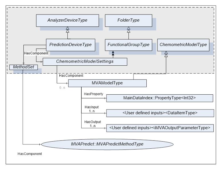
To expose a prediction service on an existing ADI server independent of the rest of the ADI server:
- Create a MVAPredictMethodType instance named MVAPredict on the AnalyserDevice or its derived object on the ADI server.
- Add a HasComponent reference from the AnalyserDevice.MethodSet object to the MVAPredict method.
- Create a FunctionalGroup named ChemometricModelSettings on the AnalyserDevice or its derived object of the ADI server.
- Add a HasComponent reference from the AnalyserDevice object to the ChemometricModelSettings FunctionalGroup.
- Create MVAModelType objects in the ChemometricModelSettings FunctionalGroup.
- Add a HasComponent references from the ChemometricModelSettings to each MVAModelType object.
From that point, models may be predicted individually using MVAPredict method. Models may also be updated using the OPC UA Write service.
The MVAModel Variables are used to hold the description of a mathematical process and associated information to convert scaled data into one or more derived values. MVAModelType is formally defined in Table 115
All MVAModel Variables are located in the ChemometricModelSettings FunctionalGroup on a Stream. It may also be located ChemometricModelSettings FunctionalGroup on the AnalyzerDevice if they are used only in the context of the prediction service.
Table 115 – MVAModelType Definition
|
Attribute |
Value |
|||||
|
BrowseName |
MVAModelType |
|||||
|
IsAbstract |
True |
|||||
|
References |
NodeClass |
BrowseName |
DataType |
TypeDefinition |
ModellingRule |
|
|
Subtype of the ChemometricModelType defined in ADI specification |
||||||
|
HasProperty |
Variable |
MainDataIndex |
Int32 |
PropertyType |
Mandatory |
|
|
HasOutput |
Variable |
<User defined Output#> |
- |
MVAOutputParameterType |
OptionalPlaceholder |
|
MainDataIndex is the index of the Inputs parameter that is used as MainData for the source timestamp. All derived / predicted data will have this timestamp.
The output parameter descriptions, referred by HasOutput ordered references, shall appear in the same order as the Outputs array of the MVAPredict method. It shall be possible to use these parameters directly without having to do intermediate mathematic or method call.
Table 116 summarizes constraints on Variable Attributes for MVAModelType.
Table 116 - Setting OPC UA Variable Attributes for MVAModelType
|
Attributes/Properties |
Description |
|
Value |
Binary blob containing all elements of the chemometric model |
|
DataType |
ByteString |
|
ValueRank |
Always set to -1 (Scalar) |
|
ArrayDimensions |
Not applicable |
The MVAOutputParameterType describes output paramaters of the MVAModelType and MVAPredictMethodType.
MVAOutputParameterType is formally defined in Table 117.
Table 117 – MVAOutputParameterType Definition
|
Attribute |
Value |
|||||
|
BrowseName |
MVAOutputParameterType |
|||||
|
IsAbstract |
False |
|||||
|
References |
NodeClass |
BrowseName |
DataType |
TypeDefinition |
ModellingRule |
|
|
Subtype of the DataItemType defined in [OPC 10000-8] |
||||||
|
HasProperty |
Variable |
WarningLimits |
Range |
PropertyType |
Optional |
|
|
HasProperty |
Variable |
AlarmLimits |
Range |
PropertyType |
Optional |
|
|
HasProperty |
Variable |
AlarmState |
AlarmStateEnumeration |
PropertyType |
Mandatory |
|
|
HasProperty |
Variable |
VendorSpecificError |
String |
PropertyType |
Optional |
|
|
HasComponent |
Variable |
Statistics |
MVAOutputParameterType [] |
BaseDataVariableType |
OptionalPlaveholder |
|
WarningLimits and AlarmLimits describe the ranges used to determine the acceptable limits of the resulting numerical MVAOutputParameter value. These values shall be set for numerical values.
In terms of automation, if value is:
value ˂ AlarmLimits.Low → ALARM_LOW
WarningLimits.Low ≤ value ˂ AlarmLimits.Low → WARNING_LOW
WarningLimits.Low ≤ value ≤ WarningLimits.High → NORMAL
WarningLimits.High ˂ value ≤ AlarmLimits.High → WARNING_HIGH
AlarmLimits.High < value → ALARM_HIGH
AlarmState describes if the resulting MVAOutputParameter value is acceptable for example within the value limits. However, a value may be between the limits and still be in alarm due to other model consideration or for example, if a classification model is not able to classify a given sample.
Table 118 – AlarmStateEnumeration Values
|
Value |
Description |
|
NORMAL_0 |
Normal |
|
WARNING_LOW_1 |
In low warning range |
|
WARNING_HIGH_2 |
In high warning range |
|
WARNING_4 |
In warning range (low or high) or some other warning cause |
|
ALARM_LOW_8 |
In low alarm range |
|
ALARM_HIGH_16 |
In high alarm range |
|
ALARM_32 |
In alarm range (low or high) or some other alarm cause |
The Statistics is an array of statistics generated at the same time as the MVAOutputParameter that qualifies it.
The VendorSpecificError contains detailed vendor specific error message explaining the alarm state.
The DataType attribute of MVAOutputParameter may be:
- AnalogItemType for scalar value or unstructured array. In this case, WarningLimits and AlarmLimits shall be set. EngineeringUnits should be set.
- ArrayItemType subtype if parameters like spectrum.
- DataItemType for String
It is strongly recommended to express MVAModel parameters in terms of high level types, for example, a spectrometer produces spectra that are YArrayItemType. The address space should expose a single parameter for it rather than N scalar values where N is the number of data points in the spectrum. This may imply that models shall be built using some convention rules, but doing so, really simplify the interaction with the prediction service of the ADI server. For example:
- If all scalar variables defining an YArrayItemType are prefixed with something like "NIR_", then the SetConfiguration, LoadModel may easily detect it and create the right parameter type.
- Use a convention where the first variable is the MainData variable or prefixing the MainData variable variables with the "MainData_" prefix may help to automatically find the MainDataIndex.
The Predict method should be able to extract the required range from a high level type input parameter. For example, if the input parameter is a spectrum with a X axis range of 400cm-1 to 5000cm-1, it shall be possible to pass a spectrum with a range of 200cm-1 to 6000cm-1 to the Predict method and the Predict method shall be able to extract the right region.
To guarantee the correctness of the predictions, the server should apply some validation rules to verify that the input parameters are compatible with the model, for example, for spectral data, the validation may include:
- The alignment of the sampling grid of spectral data shall be compatible with the model.
- The spectral range of the input spectrum is wide enough to cover the range expected by the model.
Inputs and Outputs parameters shall not be a brutal dump of the API of the vendor predictor, but rather express in terms of what an end user needs to see. It does not forbid exposing the API structures, but often these structures are very difficult to use for "process clients" like DCS or SCADA.
All MVAModels may be predicted directly by calling the MVAPredict method described in Table 119.
Table 119 - MVAPredictMethodType
|
Method |
Description |
|||
|
MVAPredict |
Predict Outputs using the TargetModel against these Inputs. |
|||
|
|
InputArguments |
|||
|
|
Name |
dataType |
ValueRank / arrayDimension |
Description |
|
|
TargetModel |
NodeId |
-1[0] |
NodeId of the MVAModel to be predicted. |
|
|
MainDataIndex |
Int32 |
-1[0] |
Index of the Inputs parameter that is used as MainData for the source timestamp. |
|
|
Inputs |
ObjectType |
1[x] |
Input parameters as defined by Inputs. |
|
|
OutputArguments |
|||
|
|
||||
|
|
Outputs |
ObjectType |
1[x] |
Output parameters as defined by Outputs. |
All fields of each Inputs and Outputs arguments must be filled, the user relies on them to discover the model information.
The vendor specific predictor return code should be returned using the DiagnosticInfo.SymbolicId.
The role of the MVAPredict method is really to allow a client to predict against the target MVAModel. The MVAPredict method:
- May be called at any time after the AnalyserDeviceStateMachine reaches the Operating state if the MVAModels are located in the ChemometricModelSettings located at AnalyserDevce level. Potential conflicts with AnalyserChannel operations like loading configuration shall be handled by the implementer following the rules describe below.
- May be called at any time after the AnalyserChannel reaches the Idle state, during Idle, Starting and Execute state, if the MVAModel are attached to a given Stream. This will avoid potential conflicts with AnalyserChannel operations like loading configuration.
- May be called more than once concurrently by the same client.
- May be called concurrently by more than one client at the same time.
- Shall produce output MVAOutputParameters that may be used directly without having to do intermediate mathematic or method call.
This is the server responsibility to deal with multi-threading issues. The client side shall never have to deal with these issues. It is perfectly legal to serialize all requests on a given model and even at the Predictor level, as long as the client does not have to be aware of it.
The MVAPredict method Executable and UserExecutable attributes shall be used to signal when MVAPredict may be called or not.
The implementer may allow some MVAModels to be updated directly by writing the Value attribute of the MVAModel. For example, let say that the Value attribute is an exact copy of the model file, the client application only has to use the OPC UA Write service to transfer the model directly to the UA server. If the model is too large to fit in a single UA message, the model may be transferred in chunk using the NumericRange parameter of the Write service.
All ADI time management rules apply:
- All output parameters shall have the same timestamp as the main parameter, the one defined by MainDataIndex.
To avoid unexpected behaviours, the following rules must be applied when models are updated with the Write service:
- ADI server shall verify the integrity / validity of the Model ByteString and returned an error code if not correct without modifying anything in the actual server configuration. If the model is transferred in chunks, the final verification shall be done on the write of the last chunk.
- ADI address shall be updated to reflect the new model.
- ADI server shall handle multi-threading issues where a GetConfiguration, SetConfiguration GetConfigDataDigest and others, while updating the models. This may be done by serializing the requests as long as the client does not have to be aware of it.
- ADI server shall return the vendor specific predictor return code using the DiagnosticInfo.SymbolicId.
If the MVAModel is used to evaluate values appearing in any AcquisitionData FunctionalGroup, the following supplemental rules must also be applied:
- MVAModel objects may only be updated when the AnalyserChannel is in Stop state.
- ADI server shall update/change the Configuration and the ConfigDataDigest if the new model is different from the previous one and only in that case.