The wire harness manufacturing industry is known for having multiple types of machines, from simple benchtop machines that require a manual operator to the full-scale automatic machines capable of manufacturing a harness. The goal of this Companion Specification is to facilitate the integration of this disparaged set of equipment, and thus multiple implementation scenarios are possible.
The basic minimalistic scenario allows an OPC UA server to expose its nameplate information, a reduced set of equipment states, and a minimalistic job control to return the job results and possibly material consumption information. This scenario only needs to implement the minimal mandatory OPC Machinery and job control interfaces, and does not need to deal with advanced interfaces such as the VEC-derived data models. Note that this scenario requires the article and part definitions to be managed in the machine, as well as the order of the jobs to be managed by the operator at the machine, including delegating the validation of quality validation processes (see Figure 15).

Figure 15 – Simple client scenario
Figure 16 describes a simple scenario of the production of a single wire, two-sided crimped product:
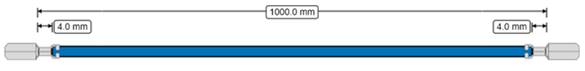
Figure 16 – Example of a simple article
For illustration purposes, assume that we want the following production flow:
- A verification job with 1 piece for quality control purposes
- 2 subsequent production batches of similar size.
The simplest workflow (see Figure 17) for this implementation would require the MES to define 3 jobs (it is possible to group these jobs in a job group, this will be discussed after this example):
- Job1:
- Quantity: 1 piece
- Article ID (All parts and article information are already stored in the machine)
- Verification parameters: VerifyWireLength, VerifyCrimpHeight side1, VerifyPullOutForce side1 VerifyCrimpHeight side2, VerifyPullOutForce side2
- Machine produces the sample
- Operator measures the requested parameters, including the pull-out force on both ends. The machine stores the reference CFA that will be needed in later production jobs.
- Machine sends Job1 results, including measured values, back to MES
- ActualLength
- Side1. ActualCrimpHeight
- Side1. ActualCrimpPullOutForce
- Side2.ActualCrimpHeight
- Side2.ActualCrimpPullOutForce
- MES verifies that the results are within tolerances
- MES sends Job 2
- Quantity: 5 pieces
- Article ID, referencing WireID, TerminalID1, TerminalID2
- Monitoring: CFA
- Machine produces Piece1
- Machine measures CFA
- Machine sends event: Piece1 produced with CFA values (or reference to data), and Timestamps
- Machine produces Piece2
- Machine measures CFA
- Machine sends event: Piece2 produced with CFA values (or reference to data), and Timestamps
After all pieces are produced, the machine sends the job result.
Figure 17 – Simple job scenario
The concept of JobGroupID has been developed with the goal of allowing MES and production plants to keep their existing processes, using one ID to reference all parts in the above jobs using the same logical JobGroupID (see Figure 18).
The JobGroupID is an optional job parameter that allows the MES to define multiple jobs, as in the example above, and provide an execution order. This makes it possible to add re-verification or post-production jobs, if desired.
Note that this Companion Specification does not cover the scenario of changing materials (for example, when a wire trommel runs empty and needs to be replaced, which may require a new validation). These are jobs that are usually coordinated by the machine.
Also note that the first scenario above allows for a check step within the MES, required before the second job is stored and started. The JobGroupA scenario below only collects the validation values of the verification/sample job.
This simple implementation can be complemented by adding part management, using the VEC definition of input material such as Wire, Terminal, Seals, etc. An additional optional step would be to send the actual article specification definition. In such a scenario, the machine would be able to return verification and monitoring information for every node in the article description.
Types of clients:
A client can be as simple as a basic monitoring application that can display and aggregate the machine states to present KPI’s on the usage of the machine, as well as list the jobs being produced at the machine. Or, it can be as complex as a full MES, providing part and article information to the machine to have control over several process parameters. Note that multiple clients could coordinate their activities to manage the complex data flows required for production. For example, one client could manage the parameters for all parts used in production, while another client could control the current production jobs.
Figure 19 – Multiple clients scenario
Some selected scenarios:
- A simple server implementing the basic machinery and job control needs to implement:
- Component identification and nameplate
- Operating state
- ISA95JobOrderReceiverObjectType with the store and clear methods
- ISA95JobResponseProviderObjectType to parse the job production results
- A server that wants to enable control of the validation of quality parameters during production must be aware of all the points mentioned above, plus:
- VEC product definition for the harness to be manufactured
- VEC part definition of the material used to produce the harness, including their specifications
- Understanding of the article specification structure to understand which processes the client expects to be executed
- Relevant ResultDataType to provide production monitoring results
- A simple client with dashboard functionality, without the need for control, would implement the following:
- Component identification and nameplate
- Operating state
- ISA95JobResponseProviderObject