
4 General information to Weihenstephan Standards and OPC UA
4.1 Introduction the Weihenstephan Standards in general
One of the main challenges in the food and beverage as well as in the packaging industry is the production of high-quality products at acceptable market prices. To remain competitive, an effective IT assistance for their in-company processes is used in form of production management systems, so-called Manufacturing Execution Systems (MES). The MES is responsible for refining the production orders, which are roughly planned in the Enterprise Resource Planning (ERP) by assigning them to production lines and monitoring the order in production. The functions also include reporting efficiency parameters back to the ERP and optimizing production processes.
The strength of the Weihenstephan Standards is that they are practical and specifically adapted to a domain.
The Weihenstephan Standards are currently available for four different domains:
WS Pack for the packaging and bottling industry, published in 2005
WS Food for the food processing industry, published in 2010
WS Bake for the baking industry, published in 2015
WS Brew for the process area of breweries and beverage companies, published in 2019
4.1.1 Benefits of the Weihenstephan Standards
The advantages of the Weihenstephan Standards are that they greatly simplify the definition of MES functionalities and the data points required for them during the project planning phase. In the implementation phase, the time required can be greatly reduced by using WS tools, which leads to a considerable reduction in costs.
This is possible because the Weihenstephan Standards take on three tasks (see Figure 1):
exemplary definition of MES functionalities that are specifically tailored for a WS domain
definition of data points derived from the MES functions
definition of the communication protocol and information model between the data sources and the MES

On the way to Industry 4.0, the hierarchical structures of the automation pyramid are breaking down more and more. This is also reflected in the Weihenstephan Standards, the data points required for the MES functionalities are not only provided directly by machines. Instead, the data is already aggregated and made available by process control systems, for example. Figure 1 illustrates the structured communication between an MES and different communication partners in a heterogeneous system for the provision of data according to the Weihenstephan Standards.
4.1.2 Exemplary definition of MES functionalities and Industry 4.0
Within a WS domain, the processing of machine and process data is defined for various MES functions that are required in the respective domains. The standard shows how data points can be used to calculate parameters, track batches or create clear production reports.
The Weihenstephan Standards cover exemplary the following areas for MES functionalities:
Efficiency analysis
KPIs
Production control
Material management
Batch tracing
Quality control
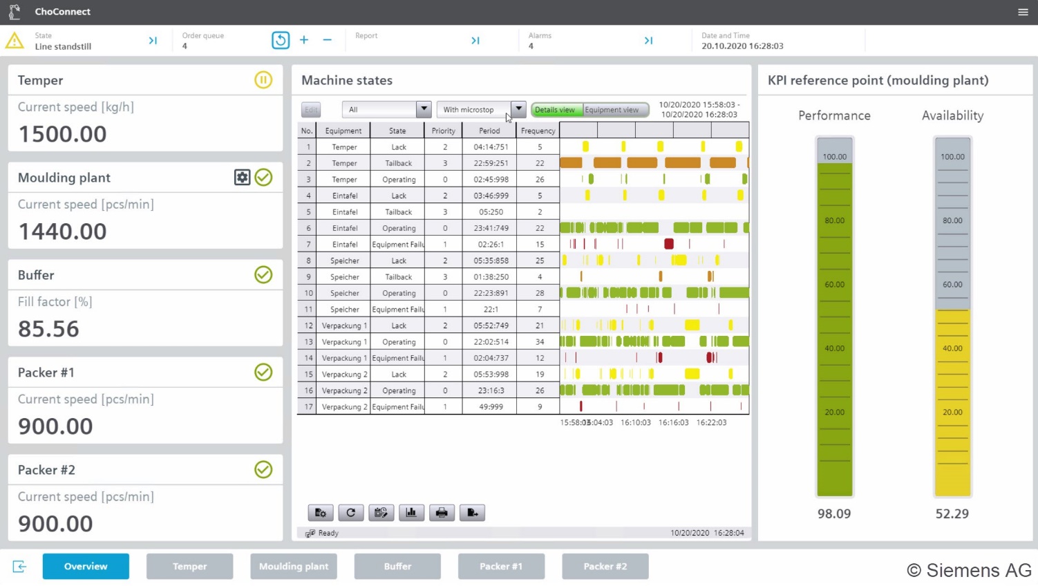
In addition, WS DataPoints enable extensive visualization functions or continuous production monitoring, e.g. with regard to production efficiency and machine performance.
An example of such visualization is the quick comparison of production efficiency shown in Figure 2.
4.1.3 WS DataPoints and WS Categories
Both the WS BrowseName and the WS TagNumber are unique for the identification of a data point. In OPC UA for Weihenstephan Standards the WS BrowseName is used for identification; in WS Protocol this is mainly the WS TagNumber. The prefix WS_ in the WS BrowseName indicates that it is a data point of the Weihenstephan Standards. Members of the WS Industrial User Group can add more data points to their machines with their own vendor-specific prefix. The assignment of the WS TagNumber is defined in the WS Protocol. The WS DisplayName of a WS DataPoint can be defined in different languages and serves as a short description for e.g. the labelling of fields in an HMI. The description of a data point contains the exact definition of this data point. The description can also be provided in different languages. The WS DisplayName and the description of a data point are available at least in English. Each data point is assigned to a category. The available categories are listed and described in Table 10. The Access permission property determines whether a data point can only be read or can also be written via the interface.
The data type of a WS DataPoint is defined depending on the interface used. See chapter 4.1.4.
WS DataPoints of all domains in the Weihenstephan Standards are structured according to the same scheme (Table 9).
| Property | Description | Example |
| WS BrowseName | The WS BrowseName is used to uniquely identify a WS DataPoint. In OPC UA this corresponds to the Browse-Name. | WS_Temp_Min |
| WS DisplayName | The name is used to describe a WS DataPoint and can be displayed in different languages. In OPC UA this corresponds to the display name. | EN: Minimum Temperature DE: Minimale Temperatur |
| WS Category | The WS DataPoints are divided into different categories. An overview of the categories can be found in Table 10. | Computed values |
| WS TagNumber | The WS TagNumber is mainly used to uniquely identify a WS DataPoint in WS Protocol. In WS OPC UA the WS TagNumber can be added to each WS DataPoint optionally. | 2006 |
| Access permission | Access rights of a client to a WS DataPoint. | Read only |
| Description | Definition of the content of a WS DataPoint. | EN: This data point gives the minimum temperature value during an operation/procedure. DE: Dieser Datenpunkt gibt die minimale Temperatur während einer Operation/Prozedur an. |
| Base quantity/engineering units | Informs about the base quantity of the WS DataPoint and gives a recommendation for the engineering units used for this WS DataPoint. The recommendations follow the UNECE code or domain-specific recommendations. | °C / °F or Packages / Minutes |
| WS OPC UA type definition | The type definition that is used for a WS DataPoint in WS OPC UA. | WSAnalogUnitType |
| WS OPC UA data type | The data type that is used for a WS DataPoint in WS OPC UA. | UInt32 |
| WS Protocol data type | The data type that is used for a WS DataPoint in WS Protocol. | Real |
| WS Protocol annotation | In the WS Protocol, information about a WS DataPoint can be added in the annotation. For example, the unit of a variable. WS OPC UA provides this information directly in the data type. | The engineering unit must be indicated in the device description file |
| Categories | Descriptions |
| Alarms | Data points in this category display alarm messages. In the Weihenstephan Standards it is assumed that the affected machine can no longer operate as usual and has been stopped. Only the first-up message is always displayed. This remains until a fault has been rectified. |
| Batch and article tracing | These WS DataPoints are used for tracking and tracing. |
| Computed values | Computed values are measured values which have been pre-processed by an application-oriented function either on PLC or data acquisition level. For example, a data point reports either a minimum, maximum or mean value of a unit procedure, an operation or a specific timeframe. All data points shall have one engineering unit. |
| Counters | Counters are used to record quantities and sometimes also times (e.g. an operating hours counter). The counts become larger with time. Only looping (cycle) counters must be used. The operating cycles of high maintenance components must be recorded for all machines. All data points shall have one engineering unit. |
| Identification | This category contains data points that describe a WS machine in more detail. These data points are general and defined in CS OPC UA for Machinery. |
| Machine communications | The WS DataPoints in this category are required for the WS Protocol communication interface and are not available for WS OPC UA. |
| Measured values | In the Weihenstephan Standard, measured values are understood as the data which are being collected at sensor level. These can be temperatures, pressures or the current speed of a conveyor belt, for example. All data points shall have one engineering unit. |
| Operating modes | WS DataPoints in this category describe the operating modes and machine states of the respective machines or units or of individual modules of these. |
| Operating states | WS DataPoints in this category describe the operating states of the respective machines or units or of single modules of these. |
| Parameters | In the category Parameters data points are understood which are set externally via the communication interface. This can be for example the desired speed of a conveyor belt but also the type of beer currently being processed. All data points should have a engineering unit if possible. |
| Programs | WS DataPoints in this category describe the programs of the respective machines or units or of individual modules of these. |
| Warnings | Data points in this category indicate warning messages. In the Weihenstephan Standards it is assumed that the machine concerned is no longer working in the target range but has not yet been stopped. The latest warning message will remain until this warning situation is resolved. |
4.1.4 WS Communication interfaces
As a link between production and ERP (see Figure 1), an MES requires communication interfaces to the subordinate machines and the higher-level ERP. The communication with the ERP is usually done via standard mechanisms such as SQL or XML, while the connection down to the machines and process control systems is often complex and expensive. There are many different communication standards in automation systems, and the availability of data relevant to the MES varies greatly from machine to machine, requiring complex engineering to connect these different systems.
To meet the challenge of different communication standards in automation systems, the Weihenstephan Standards defines two universal communication interfaces for connecting different machine and process control systems to an MES:
WS Protocol
WS OPC UA
With “WS-Protocol - Physical Interface Specifications”, a specified WS communication interface for data exchange between higher-level IT systems was developed in 2005. It is based on Ethernet TCP/IP and provides proprietary communication commands that allow easy implementation independent of hardware, software and platform. For further information please refer to https://www.weihenstephan-standards.com/.
The present document CS OPC UA for Weihenstephan Standards now provides a second opportunity to ensure that the Weihenstephan Standards meets the requirements for communication in an Industry 4.0 environment.
4.1.5 WS Document structure
The Weihenstephan Standards consist of a number of individual documents. Each document considers a particular aspect of the WS. Figure 3 gives an overview of the individual document parts. Table 11 briefly describes the document parts.
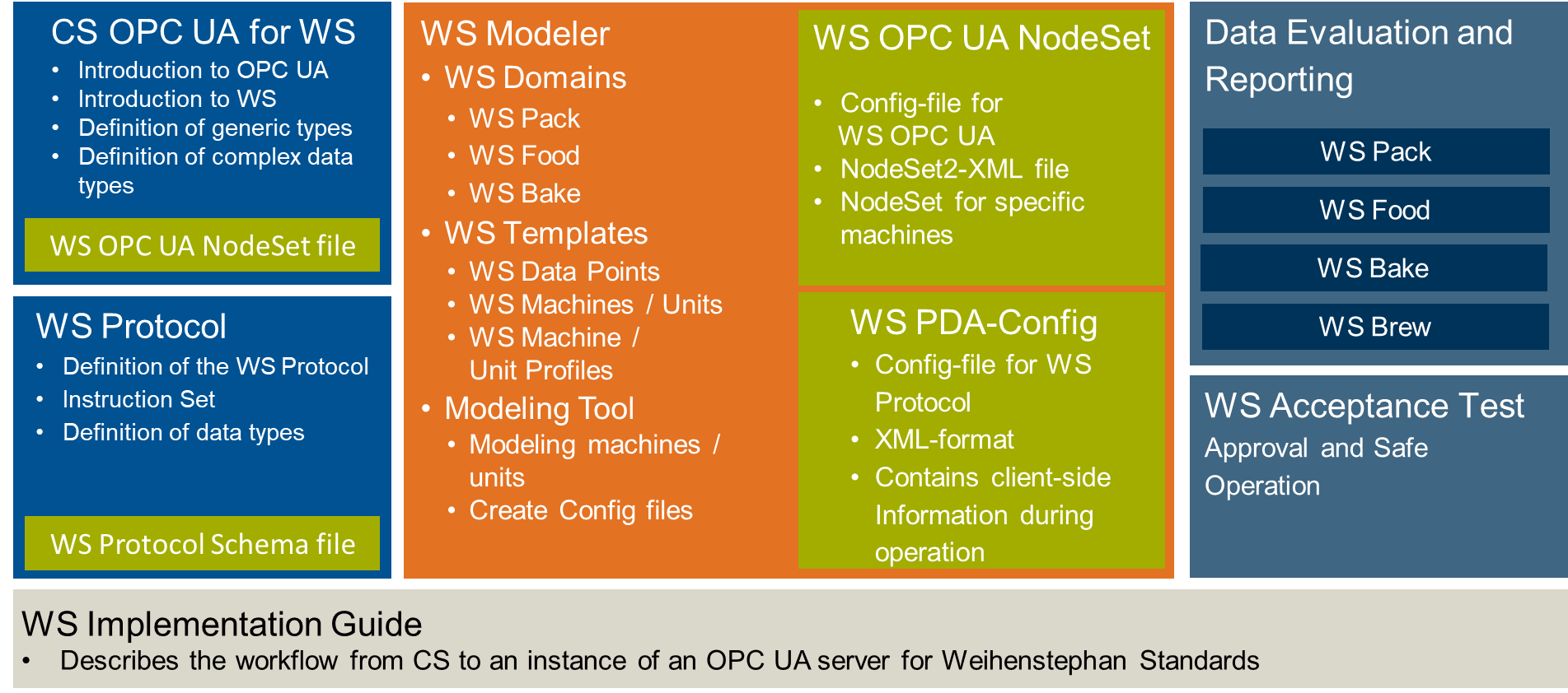
The content of the separate document parts is described in detail in Table 11. The documents can be obtained from the website https://www.weihenstephan-standards.com.
| WS document parts | Descriptions | |
| Implementation Guide | The implementation guide explains both the WS document structure and the workflow for creating a WS Server. | |
| Data Evaluation and Reporting | For each WS Domain there is a separate Data Evaluation and Reporting document. This document describes exemplary MES functionalities. | |
| WS Modeler | The WS Modeler is a modeling tool that covers the following aspects. | |
WS Templates | For each WS Domain there is a WS Template. A WS Template consists of three parts. | |
WS DataPoints | Definition of the WS DataPoints. In Table 9 the defined properties of a data point are described. | |
WS Machine / Unit Profiles | Definition of the WS Machine / Unit Profiles | |
Permutation tables | This table defines which WS DataPoints are mandatory or optional for a certain WS MachineProfile. | |
| Modeling Tool | The modeling tool to create an information model for a WS MachineClass. The tool can export the information model for both WS OPC UA and WS Protocol. | |
| CS OPC UA for WS | This Companion Specification for the Weihenstephan Standards. | |
| WS OPC UA NodeSet | A NodeSet file describes the information model of a specific machine for transmission with WS OPC UA. | |
| WS Protocol | Description of the proprietary communication standard WS Protocol. | |
| WS PDA-Config | A PDA-Config file describes the information model of a specific machine for transmission with WS Protocol. | |
| WS Acceptance Test | Guideline for the complete documentation of installation, commissioning and the events occurring during operation. This document provides recommendations for clarifying responsibilities and avoiding errors through correct operation. | |
4.2 Introduction to OPC Unified Architecture
4.2.1 What is OPC UA?
OPC UA is an open and royalty free set of standards designed as a universal communication protocol. While there are numerous communication solutions available, OPC UA has key advantages:
A state of art security model (see OPC 10000-2).
A fault tolerant communication protocol.
An information modelling framework that allows application developers to represent their data in a way that makes sense to them.
OPC UA has a broad scope which delivers for economies of scale for application developers. This means that a larger number of high-quality applications at a reasonable cost are available. When combined with semantic models such as OPC UA for Weihenstephan Standards, OPC UA makes it easier for end users to access data via generic commercial applications.
The OPC UA model is scalable from small devices to ERP systems. OPC UA Servers process information locally and then provide that data in a consistent format to any application requesting data - ERP, MES, PMS, Maintenance Systems, HMI, Smartphone or a standard Browser, for examples. For a more complete overview see OPC 10000-1.
4.2.2 Basics of OPC UA
As an open standard, OPC UA is based on standard internet technologies, like TCP/IP, HTTP, Web Sockets.
As an extensible standard, OPC UA provides a set of Services (see OPC 10000-4) and a basic information model framework. This framework provides an easy manner for creating and exposing vendor defined information in a standard way. More importantly all OPC UA Clients are expected to be able to discover and use vendor-defined information. This means OPC UA users can benefit from the economies of scale that come with generic visualization and historian applications. This specification is an example of an OPC UA Information Model designed to meet the needs of developers and users.
OPC UA Clients can be any consumer of data from another device on the network to browser based thin clients and ERP systems. The full scope of OPC UA applications is shown in Figure 4.

OPC UA provides a robust and reliable communication infrastructure having mechanisms for handling lost messages, failover, heartbeat, etc. With its binary encoded data, it offers a high-performing data exchange solution. Security is built into OPC UA as security requirements become more and more important especially since environments are connected to the office network or the internet and attackers are starting to focus on automation systems.
4.2.3 Information modelling in OPC UA
4.2.3.1 Concepts
OPC UA provides a framework that can be used to represent complex information as Objects in an AddressSpace which can be accessed with standard services. These Objects consist of Nodes connected by References. Different classes of Nodes convey different semantics. For example, a Variable Node represents a value that can be read or written. The Variable Node has an associated DataType that can define the actual value, such as a string, float, structure etc. It can also describe the Variable value as a variant. A Method Node represents a function that can be called. Every Node has a number of Attributes including a unique identifier called a NodeId and non-localized name called as BrowseName. An Object representing a ‘Reservation’ is shown in Figure 5.

Object and Variable Nodes represent instances and they always reference a TypeDefinition (ObjectType or VariableType) Node which describes their semantics and structure. Figure 6 illustrates the relationship between an instance and its TypeDefinition.
The type Nodes are templates that define all of the children that can be present in an instance of the type. In the example in Figure 6 the PersonType ObjectType defines two children: First Name and Last Name. All instances of PersonType are expected to have the same children with the same BrowseNames. Within a type the BrowseNames uniquely identify the children. This means Client applications can be designed to search for children based on the BrowseNames from the type instead of NodeIds. This eliminates the need for manual reconfiguration of systems if a Client uses types that multiple Servers implement.
OPC UA also supports the concept of sub-typing. This allows a modeller to take an existing type and extend it. There are rules regarding sub-typing defined in OPC 10000-3, but in general they allow the extension of a given type or the restriction of a DataType. For example, the modeller may decide that the existing ObjectType in some cases needs an additional Variable. The modeller can create a subtype of the ObjectType and add the Variable. A Client that is expecting the parent type can treat the new type as if it was of the parent type. Regarding DataTypes, subtypes can only restrict. If a Variable is defined to have a numeric value, a sub type could restrict it to a float.

References allow Nodes to be connected in ways that describe their relationships. All References have a ReferenceType that specifies the semantics of the relationship. References can be hierarchical or non-hierarchical. Hierarchical references are used to create the structure of Objects and Variables. Non-hierarchical are used to create arbitrary associations. Applications can define their own ReferenceType by creating subtypes of an existing ReferenceType. Subtypes inherit the semantics of the parent but may add additional restrictions. Figure 7 depicts several References, connecting different Objects.

The figures above use a notation that was developed for the OPC UA specification. The notation is summarized in Figure 8. UML representations can also be used; however, the OPC UA notation is less ambiguous because there is a direct mapping from the elements in the figures to Nodes in the AddressSpace of an OPC UA Server.

A complete description of the different types of Nodes and References can be found in OPC 10000-3 and the base structure is described in OPC 10000-5.
OPC UA specification defines a very wide range of functionality in its basic information model. It is not required that all Clients or Servers support all functionality in the OPC UA specifications. OPC UA includes the concept of Profiles, which segment the functionality into testable certifiable units. This allows the definition of functional subsets (that are expected to be implemented) within a companion specification. The Profiles do not restrict functionality, but generate requirements for a minimum set of functionality (see OPC 10000-7)
4.2.3.2 Namespaces
OPC UA allows information from many different sources to be combined into a single coherent AddressSpace. Namespaces are used to make this possible by eliminating naming and id conflicts between information from different sources. Each namespace in OPC UA has a globally unique string called a NamespaceUri which identifies a naming authority and a locally unique integer called a NamespaceIndex, which is an index into the Server's table of NamespaceUris. The NamespaceIndex is unique only within the context of a Session between an OPC UA Client and an OPC UA Server- the NamespaceIndex can change between Sessions and still identify the same item even though the NamespaceUri's location in the table has changed. The Services defined for OPC UA use the NamespaceIndex to specify the Namespace for qualified values.
There are two types of structured values in OPC UA that are qualified with NamespaceIndexes: NodeIds and QualifiedNames. NodeIds are locally unique (and sometimes globally unique) identifiers for Nodes. The same globally unique NodeId can be used as the identifier in a node in many Servers – the node's instance data may vary but its semantic meaning is the same regardless of the Server it appears in. This means Clients can have built-in knowledge of of what the data means in these Nodes. OPC UA Information Models generally define globally unique NodeIds for the TypeDefinitions defined by the Information Model.
QualifiedNames are non-localized names qualified with a Namespace. They are used for the BrowseNames of Nodes and allow the same names to be used by different information models without conflict. TypeDefinitions are not allowed to have children with duplicate BrowseNames; however, instances do not have that restriction.
4.2.3.3 Companion Specifications
An OPC UA companion specification for an industry specific vertical market describes an Information Model by defining ObjectTypes, VariableTypes, DataTypes and ReferenceTypes that represent the concepts used in the vertical market, and potentially also well-defined Objects as entry points into the AddressSpace.