This annex provides a worked-out example of the configuration of the Information Model of an AutomationComponent using the UAFX Information Model.
This modelling process is described in an abstract way, without referencing tools or roles for the creation or editing of the model. In a concrete example, suitable or adapted engineering tools are expected to support the modelling process.
Figure F.1 is an AML Information Model example of a modular Controller for a filling machine for liquids. The figure shows the assets of the Controller: A backplane chassis, a power module “POW”, a CPU module “CPU”, an analogue input module in slot “0”, and a digital output module in slot “1”.
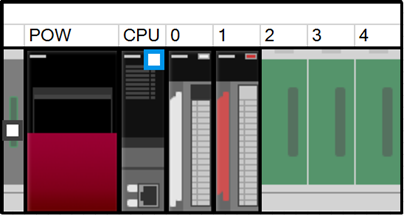
Figure F.1 – Controller for a filling machine
The Information Model of the filling machine is modelled with three FunctionalEntities: one for the fill level measurement, one for the actuation of the valve that supplies the liquid, and one for the control algorithm.
The creation of the AML Information Model can be divided into four steps:
- Instantiation of the AutomationComponentType;
- Creation of the Asset structure;
- Creation of the FunctionalEntity structure;
- Creation of the (preconfigured) DataSets.
The AML Information Model does not need to be complete at this stage in the development. The model only needs to have enough data to be ready to be handed off to the next stage in development. Each stage of the development will add more information to the model. The current stage could be having all the product data incorporated. The next stage may include the configuration data, such that the AutomationComponent can be set up and commissioned. The current stage is complete when the model has all the information needed in preparation for the next stage.
The modelling starts with the creation of an instance of the AutomationComponentType SystemUnitClass (SUC). This type is part of the OPC UA FX AML Core Libraries. One way of doing this is to directly instantiate the AutomationComponentType SUC. This is shown in Figure F.2.
A more convenient way is to start from a vendor-specific subtype of the AutomationComponentType SUC, which provides product-related data and structure in the type. This requires that the Controller vendor provides a vendor-specific OPC UA FX AML library.
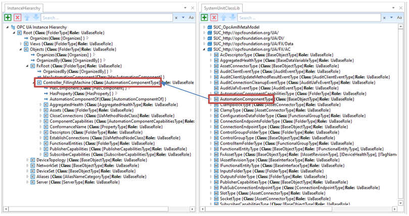
Figure F.2 – Instantiation of the SUC AutomationComponentType
The top level of the AutomationComponent instance contains important Variables for product data:
- ConformanceName: Provides the URL to the product’s listing on the OPC Foundation website under which the result of the conformance test can be found;
- ComponentCapabilities: Describes limits on the functionality provided by an AutomationComponent (e.g., number of supported logical connections, etc.);
- PublisherCapabilities and SubscriberCapabilities: Limits on the AutomationComponent for the communication functions.
In the next step, the Asset structure of the modular Controller is created using the FxAssetType SUC, which is provided by the OPC UA FX AML Libraries.
In Figure F.3, the Asset structure is shown. The first Asset is the backplane chassis R35_Rack, which can host modules through connector slots.
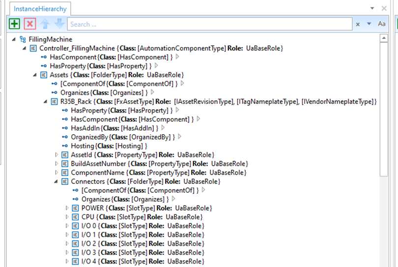
Figure F.3 – R35B_Rack with slot connectors
After the creation of the backplane chassis, the modules are created as instances of FxAssetType: A power supply module (R61P_PowerSupply), a CPU module (R04CPU_PLC), an analogue input module (R60AD4_AnalogInput) and a digital output module (RY10R2_DigitalOutput). See Figure F.4.
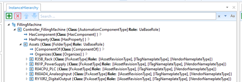
Figure F.4 – Asset modules of the controller
After creation of the modules, the available data for the identification of the Asset that is defined in the IVendorNamePlate OPC UA Interface should be added. See Figure F.5.
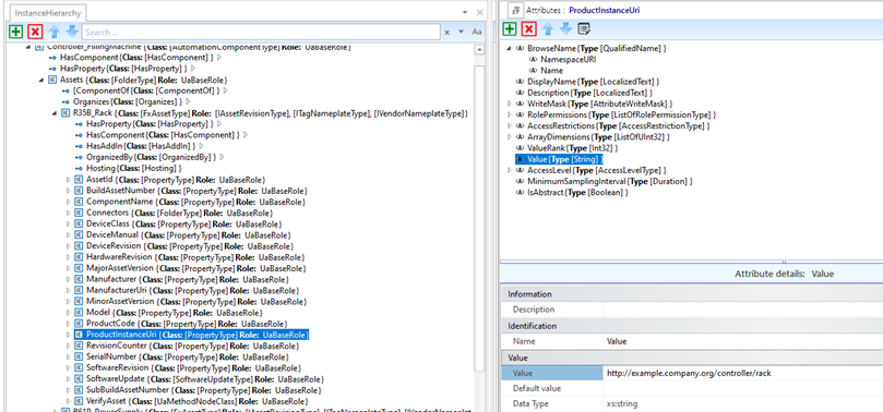
Figure F.5 – Asset identification data
In the final step for configuring the Asset structure, the modules are associated with the connector slots using HasAttachedComponent references, as shown in Figure F.6:
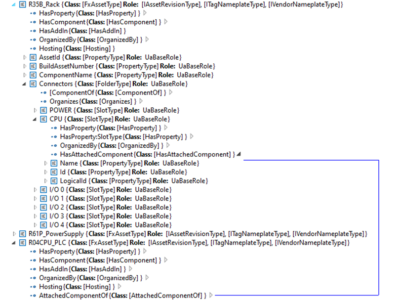
Figure F.6 – Attaching the controller module to the rack
In this step of the example, the FunctionalEntity sub-model is created. See Figure F.7.
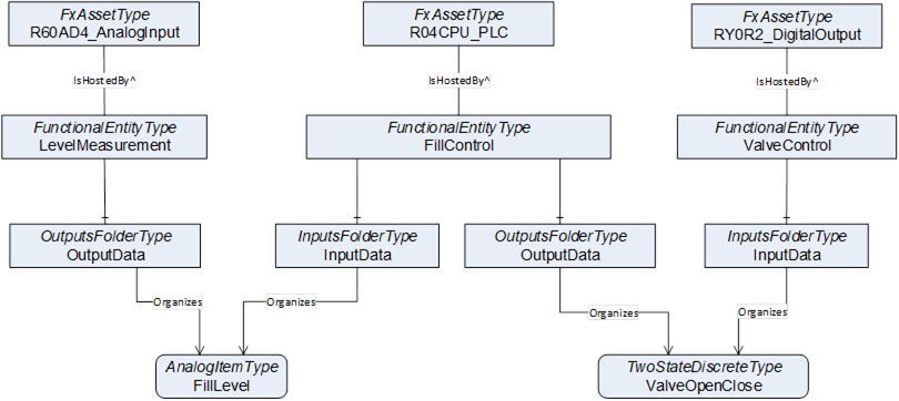
Figure F.7 – FunctionalEntity sub-model of Filling Machine example
The following steps are needed to define the FunctionalEntities:
- Creation of the FunctionalEntityType instances (The OPC UA FX AML Core Libraries provide the FunctionalEntityType SUC for defining a FunctionalEntity).
- Within each FunctionalEntity, define variables for the input, output and configuration variables and link the variables to the FunctionalEntity using Organizes references.
- Set or restrict the values in the PublisherCapabilities and SubscriberCapabilities structure. The PublisherCapabilities and SubscriberCapabilities structure exists in the FunctionalEntity sub-model at three levels: AutomationComponent, FunctionalEntity and InputData and OutputData levels.
In Figure F.8, a FunctionalEntity “FillControl” is created that represents an application for controlling a valve based on input data from a level measurement. The “FillControl” FunctionalEntity is hosted by the CPU module “R04CPU_PLC”.
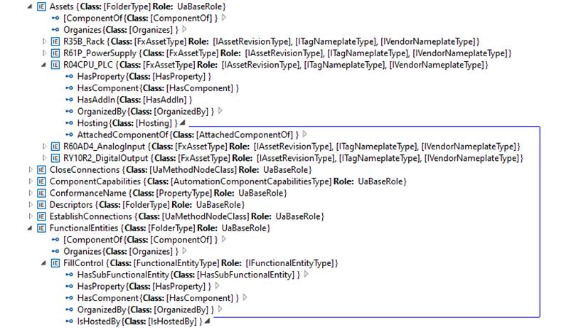
Figure F.8 – FunctionalEntity FillControl hosted by Asset R04CPU_PLC
“FillControl” uses an analog “FillLevel” input and a digital “ValveOpenClose” output variable. Both Variables are organized as InputData and OutputData of the FunctionalEntity “FillControl”.The “FillLevel” signal is coming from a FunctionalEntity “LevelMeasurement” that is hosted by the analogue input module “R60AD4_AnalogInput”, while the “ValveOpenClose” signal is sent to a FunctionalEntity “ValveControl” hosted by the digital output module “RY0R2_DigitalOutput”.
This is shown in Figure F.9.
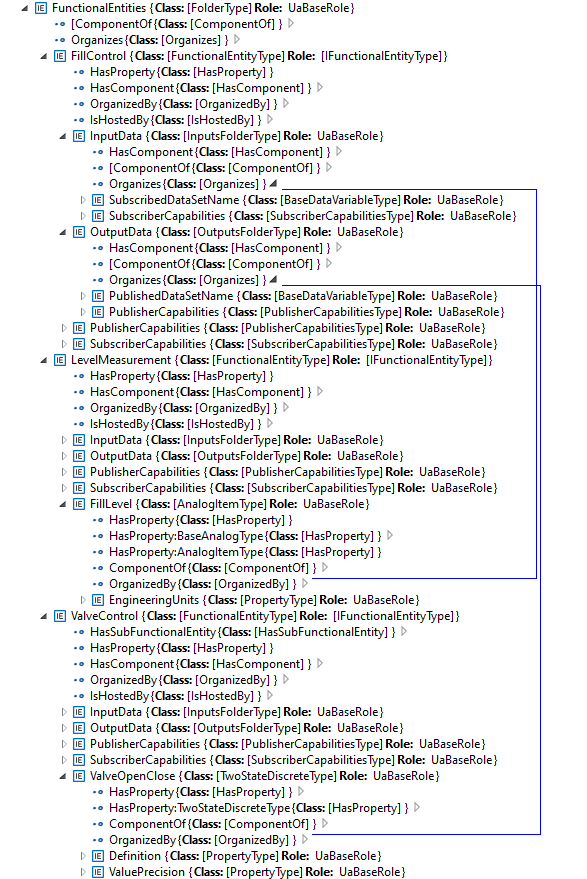
Figure F.9 – FunctionalEntity FillControl organizing input and output variables
After setting up InputData and OutputData, the capabilities of the communication are defined. For example, the SubscriberCapabilities Variables for the “FillLevel” input signals are defined as in Figure F.10:
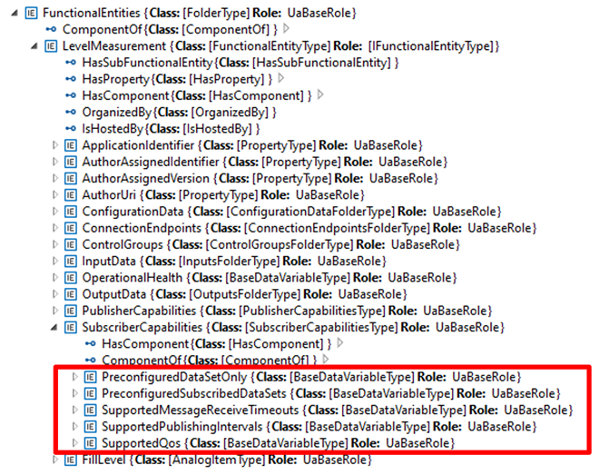
Figure F.10 – SubscriberCapabilities Variables of the LevelMeasurement FunctionalEntity
Table F.1 shows the values of the Variables used in the example:
NOTE The DataSets referenced in the table are defined in F.2.5.
Table F.1 – SubscriberCapabilities Variables and values for the LevelMeasurement FunctionalEntity
|
Variable |
Value |
|
PreConfiguredDataSetOnly |
True |
|
PreConfiguredSubscribedDataSets |
[“FillLevelDataSet”] |
|
SupportedMessageReceiveTimeouts |
min:200,max:20000,increment:50,multiplier:1;unit:milliseconds |
|
SupportedPublishingIntervals |
min:50, max:5000,increment:50,multiplier:1;unit:milliseconds |
|
SupportedQoS |
QosCategory: opc.qos.cat://priority,DatagrammQos: opc.qos.lbl://green |
Since the example is using pre-configured DataSets, the DataSets for the communication of the “FillLevel” and “ValveOpenClose” signals are defined in the next step. This is shown in Figure F.11:
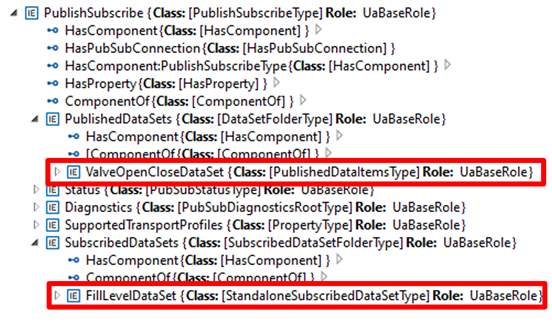
Figure F.11 – DataSets for the FillControl FunctionalEntity
Two DataSets are defined:
- A publication dataset, “ValveOpenCloseDataSet”, for the valve control messages;
- A subscription dataset, “FillLevelDataSet”, for the level measurement messages.
Figure F.12 shows the “ValveOpenCloseDataSet”, which contains the following variables:
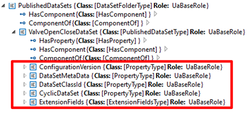
Figure F.12 – Variables in the ValveOpenCloseDataSet
Table F.2 describes the values of the variables.
Table F.2 – Variables and values of ValveOpenCloseDataSet
|
Variable |
Value |
|
ConfigurationVersion |
Structure with MajorVersion and MinorVersion with the VersionTime timestamp of the dataset configuration |
|
DataSetMetaData |
(only data elements relevant to the example are shown):Fields: [Name: ValveOpenClose,BuiltinType: Boolean,DataType:Boolean,ValueRank:-1,ArrayDimensions: Not specified,MaxStringLength: Not specified ] |
|
DataSetClassId |
Not specified |
|
ExtensionFields |
Not specified |
|
CyclicDataSet |
True |
|
PublishedData |
[ PublishedVariable: ValveOpenClose,AttributeId: Value,SamplingInterval: Not specified,DeadbandType: Not specified,DeadbandValue: Not specifiedIndexRange: Not specified,SubstituteValue: Not specified,MetaDataProperties: Not specified] |
After the offline configuration of the Filling machine, the configuration is stored in a Descriptor and further used in system engineering to set up a production line.
In this phase, as shown in Figure F.13, a System Integrator defines the ITagNameplate information, custom DataSets (if allowed), the connections between machines in the production, the communications intervals and Quality of Service (QoS) being used and Networking configuration (e.g., IP addresses, VLAN Ids).
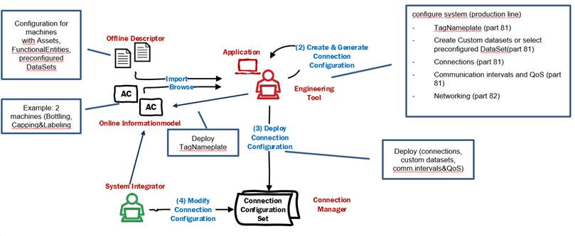
Figure F.13 – Usage of a Descriptor in subsequent engineering
As the final step, the connection information, including custom DataSets, the communication intervals and QoS, is deployed to the ConnectionManager(s), which is responsible for establishing the connections. Other information, like ITagNamePlate and Networking configuration, is deployed directly to the machines.