The following subclauses describe an example workflow to achieve the configuration and operation shown in Figure 5. As mentioned in 1, with this release, vendor-specific means are required for all networking-related End Station and Bridge Component configurations, including VLAN configuration, time synchronisation, and QoS.
The engineering workflow described in this clause follows the general workflow from OPC 10000-80 for the configuration of Connections between FunctionalEntity inputs and outputs. The workflow described in this clause goes into the details related to configuring the QoS required by those Connections. This workflow is divided into four phases: Application and QoS engineering, network configuration, system integration, and connection establishment and operation.
The example in this clause illustrates the configuration and start-up of a single communication flow between two Controllers, i.e., data is only shared in one direction, requiring a single Descriptor describing this data to be exported from an engineering tool describing one of the Controllers. UAFX Applications will typically be sharing data in both directions between the Controllers, thus requiring Descriptors to be shared in both directions.
The default networking configuration of End Station Components defined in the application and QoS engineering phase (see 5.6.4.2) of the workflow allows UAFX Stations to operate out-of-the-box with no additional networking configuration when used on a network designed with these requirements in mind. This default configuration can be adapted, e.g., to accommodate the needs of an existing network, as illustrated in the workflow’s system integration phase (see 5.6.4.4).
During the application and QoS engineering phase, Controls Engineers, working in an OfflineEngineering environment, first create the user programs and UAFX Applications and set up the (default) networking configuration of the End Station Components (see 6.3) on their Controller. Next, Controls Engineers set up the Connection configurations needed for sharing data between Controllers. As a final step, Connection configurations are transferred to a ConnectionManager that establishes the Connections during the workflow’s connection establishment and operation phase (see 5.6.4.5). This subclause describes the details of these steps, including the setup of network interface configurations and Connection information provided to the ConnectionManager. Complete details of the ConnectionManager are defined in OPC 1000081.
Figure 6 illustrates an example where two engineers jointly create a UAFX Application containing Controller A and Controller B while separated in time and space and potentially without physical devices. For example, Controller A might control a conveyor belt, and Controller B might be a line controller using this conveyor belt (Controller) as part of controlling a production line. Descriptors, defined in OPC 1000083, enable the engineers to share application information between their respective engineering tools. In this example, Controller B hosts the ConnectionManager (CM) for configuring and establishing the Connection.
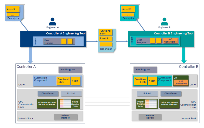
Figure 6 – UAFX Application engineering
As the first step in this example, Engineer A creates Controller A’s User Program using an engineering tool specific to Controller A. In addition to the Controller’s program, the engineering tool is used to create the UAFX Information Model representing that program. This Information Model consists of an AutomationComponent representing the entity being created by Engineer A. Part of the AutomationComponent is the functional model representing the logical functionality of the User Program. FunctionalEntities contained in the AutomationComponent represent that functional model. Input and output Variables in the FunctionalEntity expose the data to be exchanged using Connections with FunctionalEntities in another Controller. The Variables PublisherCapabilities and SubscriberCapabilities, also contained in the AutomationComponent, describe communication capabilities such as publishing intervals and, most important for the scope of this example workflow, the QoS capabilities that this AutomationComponent supports. OPC 1000081 provides details about the AutomationComponent, FunctionalEntity, the functional model, PublisherCapabilities, and SubscriberCapabilities.
To configure the use of priority-based QoS for a UAFX Application, Engineer A sets up and references a PriorityMappingTable from each physical network interface available to the UAFX Application. Virtual interfaces inherit the PriorityMappingTable from the physical interface if they do not reference a PriorityMappingTable directly. A PriorityMappingTable consists of entries that map a combination of abstract QosCategory and PriorityLabel values to concrete PCP and DSCP values for priority-based QoS at the Ethernet and IP layer, respectively. The default PriorityMappingTable settings for priority-based QoS with UAFX are defined in 6.5.4. OPC 1000014 provides detailed descriptions of QosCategory and PriorityLabel.
For priority-based QoS at the IP layer, no additional configuration is needed. For priority-based QoS at the Ethernet layer, the UAFX Station has default VLAN interfaces created as defined in 6.5.3. To this end, Engineer A may modify the VLAN IDs or add additional VLAN interfaces. The VLAN IDs or additional VLAN interfaces can also be changed during the system integration step of the workflow (see 5.6.4.4) as appropriate for the given deployment.
In either case, the VLAN interface is represented in the Information Model by an IetfBaseNetworkInterfaceType object, as described in 6.5.3. Figure 7 illustrates the Information Model of a physical interface with the name “eth0” referencing a PriorityMappingTable, DefaultPriorityMappingTable, with at least the PriorityMappingEntries defined in 6.5.4, and an associated VLAN interface named “eth0.uafx-vlan” and VID set to 100 as defined in 6.5.3.
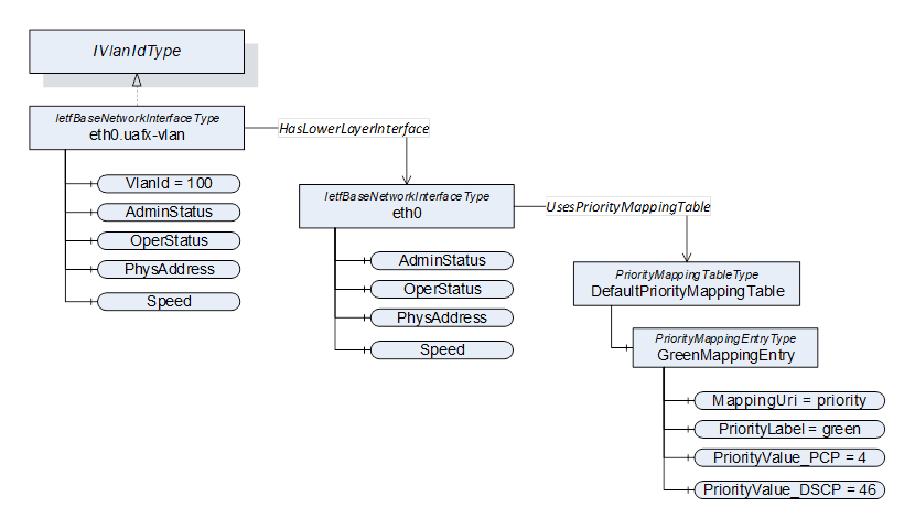
Figure 7 – Example Information Model for a physical interface
NOTE: Setting VlanId to zero results in Ethernet frames being transmitted through that interface as priority tagged frames, i.e., the VID set to zero in the VLAN Tag.
Once the configuration for Controller A is complete, Engineer A transfers the User Program, PriorityMappingTable, and all created network interfaces to Controller A using this Controller’s engineering tool. Engineer A also exports a Descriptor that is shared with Engineer B to complete the UAFX Application configuration. The exported Descriptor includes, amongst others, the AutomationComponent, FunctionalEntity(ies), PublisherCapabilities and SubscriberCapabilities (including QosCategories and PriorityLabels), PriorityMappingTable, and IetfBaseNetworkInterfaces representing Controller A’s User Program. OPC 1000081 provides the detailed definitions of ConnectionManager, PublisherCapabilities and SubscriberCapabilities, and PubSubCommunicationFlowConfiguration.
Engineer B creates the User Program and the UAFX Information Model for Controller B using an engineering tool specific to Controller B, much as Engineer A did for Controller A. Engineer B also imports the Descriptor exported by Engineer A into Controller B’s engineering tool, allowing Engineer B to configure the Connections between Controller A’s and Controller B’s FunctionalEntity(ies).
By importing the Descriptor from Controller A, Controller B’s engineering tool contains the UAFX Information Model for both Controllers, including the configuration of both Controllers’ AutomationComponent’s PublisherCapabilities and SubscriberCapabilities, PriorityMappingTable, and IetfBaseNetworkInterfaces. With this information, Engineer B configures the QoS and addresses for each Connection between the Controllers by setting the sender and receiver Address, QosCategory, and PriorityLabel Variables in the ConnectionManager PubSubCommunicationFlowConfiguration.
Figure 8 illustrates the Variables used by Controller B’s engineering tool for configuring the Connection’s QoS. This step involves setting the QosCategory and PriorityLabel Variables in the ConnectionManager’s PubSubCommunicationFlowConfiguration Variable. The available values for QoS are derived from the respective AutomationComponent’s PublisherCapabilities and SubscriberCapabilities Variables. More precisely, each Controller’s supported QoS options are described in the SupportedQos Array contained in the PublisherCapabilities and SubscriberCapabilities Variables. Each element of the SupportedQos Array, in turn, contains a single QosCategory value with its related DatagramQos Array. For QosCategory “opc.qos.cat://priority”, the DatagramQos Array contains a single element containing the supported PriorityLabel (e.g., “opc.qos.lbl://green”).
Engineering tools can ensure QosCategory is set consistently in both the sender and receiver by only listing those elements having the same QosCategory values in both Controller A and Controller B, i.e., the intersection of values from both Controllers. The list of supported PriorityLabels can be different in each Controller, so separate PriorityLabel lists are presented by the engineering tool for each side of the Connection.
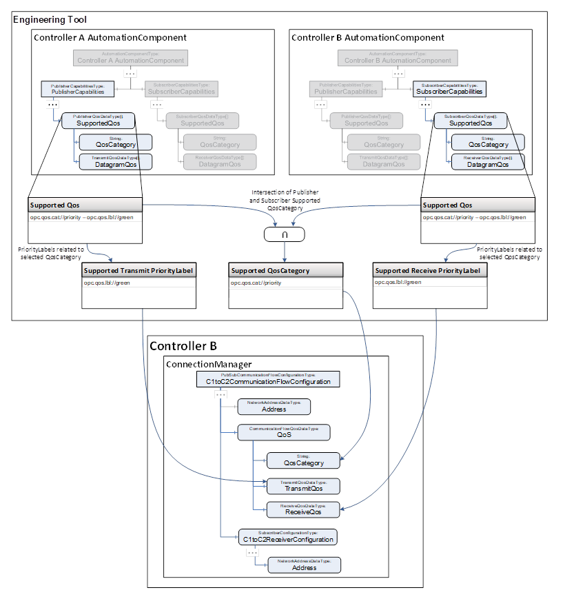
NOTE: The example in this figure only uses standard OPC UA values for QosCategory and PriorityLabel. However, a vendor can extend the labels with vendor-specific labels should they choose (e.g., acme://blue). The only QosCategory value defined in the current release of OPC 1000014 is opc.qos.cat://priority. Table 3 defines the only standard PriorityLabel value defined in this release for opc.qos.cat://priority is opc.qos.lbl://green. Future releases may define additional QosCategory and PriorityLabel values.
In addition to the QosCategory and PriorityLabel, Engineer B can set the interface configuration in the NetworkInterface Variable to be used by a Connection as part of the PubSubCommunicationFlowConfiguration sender and receiver Address parameters. A NetworkInterface Variable may either be the BrowseName of a physical interface or a VLAN interface. The NetworkInterface Variable may also be set to an empty string. In this case, the AutomationComponent chooses the appropriate network interface (e.g., using a routing table). All available network interfaces available to the UAFX Application, including VLAN interfaces, are contained in the NetworkInterfaces Folder defined in OPC 10000-22. The System Commissioner can finish the configuration of the Connections (i.e., modify the network interface and QoS selection) in the system integration phase (see 5.6.4.4).
Once the Connection configuration is complete, Engineer B transfers the Connection configurations for the ConnectionManager, including their QoS requirements, User Program, and network interface configuration, into Controller B using a vendor-specific engineering tool.
During the network configuration phase, the Network Engineer uses remote management (see 7.2) or vendor-specific means to discover the network topology (see 7.3) and further configures the interconnected UAFX Stations and network infrastructure components.
In deployments intended to use priority-based QoS at the Ethernet layer, it is recommended that all Bridge Components are configured to forward VLAN-tagged Ethernet frames with the VLAN ID(s) used by the attached UAFX Stations. To this end, the Network Engineer configures Static VLAN Registration Entries (see IEEE Std 802.1Q2022, 8.8.2) for each of these VLAN IDs for those Bridge Components. The Static VLAN Registration Entries add those ports that are connected to a UAFX Station or an IA-station interconnecting UAFX Stations in a network to the tagged member sets of the VLAN IDs. As a result, the VLAN tags are transmitted from the sending UAFX Station to the receiving UAFX Station.
In addition, the Network Engineer may also configure the use of selected TSN mechanisms in the network as appropriate for the given deployment scenario and application QoS requirements. Figure 9 illustrates two of the many different available TSN mechanism configuration options. Example 1 illustrates a configuration that entails setting PCP 4 (see Table 3) to Express and all other PCPs as Preemptible using the Frame Preemption mechanism (see 6.2.2 item g). Alternatively, as shown in Example 2, the first 200 µs of a 1 ms cycle time may be reserved for PCP 4, with the remaining 800 µs used for the remaining PCPs using the enhancements for scheduled traffic mechanism (see 6.2.2 item f).
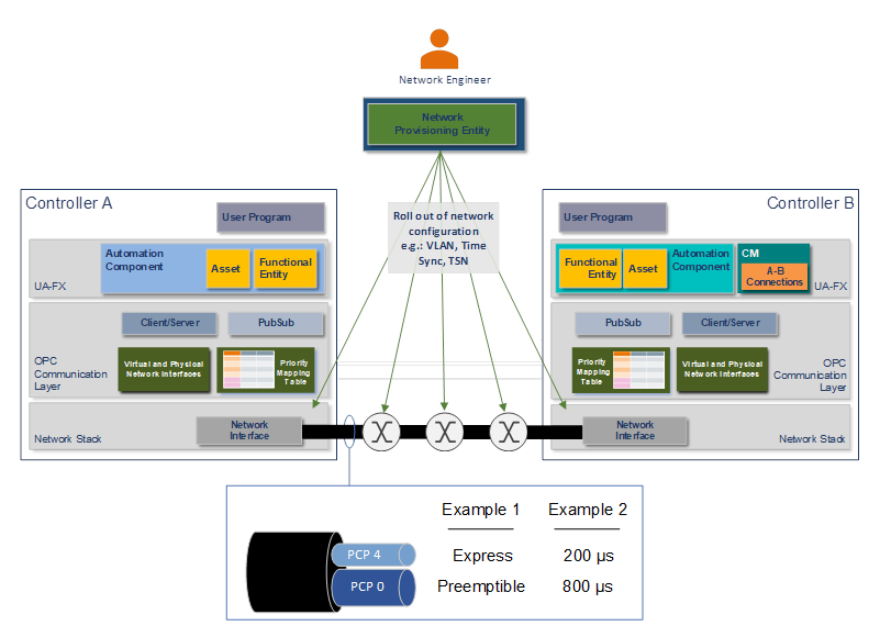
Figure 9 – Network configuration
During the system integration phase, a System Commissioner makes the necessary adjustments to adapt the Connections and network configurations for the existing network using a generic OPC UA Client or vendor-specific engineering tool, as illustrated in Figure 10.
Clause 6.5.3 specifies the default VLAN interfaces with default VLAN IDs. If the System Engineer used deviating VLAN IDs, the System Commissioner has to update the VLAN interfaces on the UAFX Stations. Additionally, new VLAN interfaces can be created if necessary.
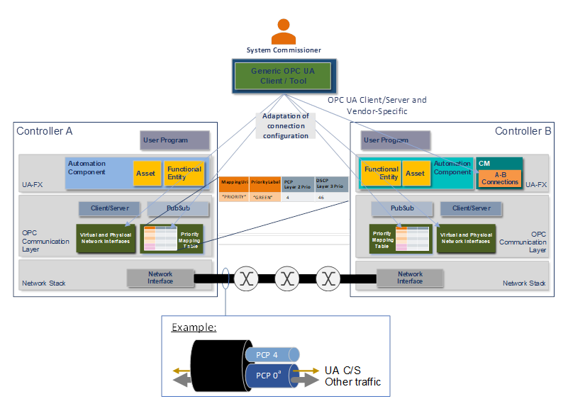
a As no OPC UA Information Model mechanism today allows the assignment of priority information for UA Client Server messages, PCP 0 is shown in this example instead of PCP 2, as defined in Table 1.
Figure 10 – System integration
Clause 6.5.4 specifies the default PriorityMappingTable assigned to the physical interfaces. Only if the Network Engineer requires a different usage of the priority values for the configured QoS mechanisms in the network does the System Commissioner update the PriorityMappingTable on all UAFX Stations accordingly (i.e., the PCP and DSCP values for the different QosCategory-PriorityLabel combinations).
NOTE A System Commissioner considers the current use of VLANs and priorities when adding UAFX Stations to an existing network and adjusts VLAN interfaces and PriorityMappingTable configurations accordingly on all UAFX Stations.
Finally, once the network interfaces and PriorityMappingTable are configured, the System Commissioner may update the PubSubCommunicationFlowConfiguration Variable in the ConnectionManager’s Information Model to adapt the Connection configurations for QoS settings and network settings such as setting destination IP addresses and network interface names. This step is only necessary if the deployment of the UAFX Station uses different values, as available in the Descriptor in 5.6.4.2. Clause 5.6.4.2 describes the Information Model objects and Variables involved in making these adjustments.
The connection establishment and operation phase begins with the ConnectionManager establishing the Connections described in its Information Model. Connection establishment is either initiated by the ConnectionManager’s internal logic or by a Client invoking a Method on the ConnectionManager as described in OPC 1000081.
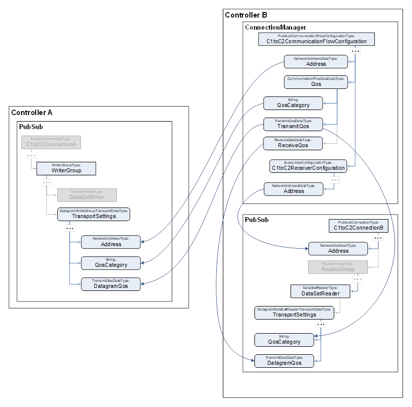
Figure 11 – PubSub QoS and addressing configuration variables
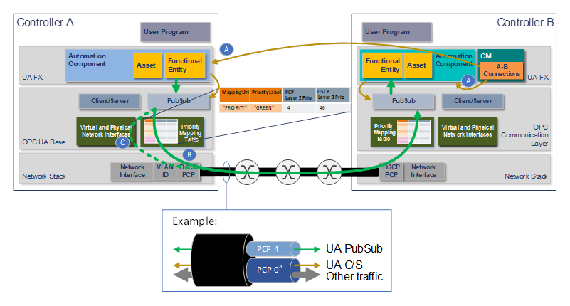
The ConnectionManager establishes Connections using the Connection configuration as set up by the Controls Engineer (see 5.6.4.2) and System Commissioner (see 5.6.4.4). Figure 11 illustrates setting up the PubSubConfiguration in Controller A and Controller B, focusing on QoS and Address as contained in the PubSubCommunicationFlowConfiguration. To this end, the ConnectionManager invokes the EstablishConnections Method on the AutomationComponents that reference the FunctionalEntities being connected, as depicted in Figure 12 label A. For details on Address and QoS, see OPC 1000014.
a As no OPC UA Information Model mechanism exists today that allows the assignment of priority or addressing information for UA Client Server messages, PCP 0 is shown in this example instead of PCP 2 as defined in Table 1, and VLAN interfaces are not shown for the UA C/S and other traffic.
Figure 12 – PriorityMappingTable operation
Once a Connection is established and communication begins, as illustrated in Figure 12 label B, the OPC UA Application and Communication Layer (see Figure 1) uses the QosCategory and PriorityLabel values in the WriterGroup with the PriorityMappingTable to derive the actual PCP and DSCP priority values to use for the corresponding OPC UA PubSub messages on the wire. Similarly, it uses the Address Variable in the WriterGroup to derive the VLAN ID value to be used in the VLAN tag, as illustrated in Figure 12 label C, for priority-based QoS with Ethernet. See OPC 1000014 for a detailed description of how the PriorityMappingTable and Address Variable are used with PubSub communications for priority-based QoS.