Secondary tobacco machines produce cigarettes and pack them ready for shipping as required by the product specification which consists of a complex bill of materials. Secondary tobacco machines produce different brands, i.e. product specifications, in production lots or batches.
A given secondary tobacco machine ordinarily produces different brands, sometimes within the same day: flexibility is a necessary requirement. Switching from brand to brand on the same machine, called brand change, sometimes requires mechanical adjustments which take several hours of highly skilled technicians’ time and is followed by a production ramp up to tune the machine to the required efficiency for the new brand.
Brands differ because of the different materials, tobacco and non-tobacco making up the shipping goods. Thus brand integrity, i.e. making sure that the finished product is made of the specified materials, is of paramount importance.
Modern secondary machines (maker, packer, filter maker, wrapper, overwrapper, case packer) are high production volume machines provided with state-of-the-art motion controls and organized in a group called workcentre to perform the full secondary production process. Within one workcentre, secondary machines are regularly provided by different OEMs and work together because highly modular in their mechanical design. Within a workcentre older generation machines are often found due to the machines’ long life-cycle. Each machine has its own HMI (sometimes more than one) and control system which sometimes is proprietary (older generations) or legacy.
Other systems (MES, MOM, SCADA, etc.) are required to exchange information with the machines primarily in the areas of production specification, performance and quality.
In most tobacco factories, the information exchange with such a varied landscape of machine is not harmonized in terms of (a) information content, (b) communication mechanism and (c) data format and structures. As a consequence, interoperability and flexibility is very limited making development efforts for integration is huge.
The TMC Working group have set out for the present companion specification to be a significant step in the direction of specifying how to have an interoperable shop floor equipment for cigarette manufacturing.
The main use case for OPC standards is the online data exchange between devices and HMI or SCADA systems using Data Access functionality. In this use case the device data is provided by an OPC server and is consumed by an OPC client integrated into the HMI or SCADA system. OPC DA provides functionality to browse through a hierarchical namespaces containing data items and to read, write and to monitor these items for data changes. The classic OPC standards are based on Microsoft COM/DCOM technology for the communication between software components from different vendors. Therefore classic OPC server and clients are restricted to Windows PC based automation systems.
OPC UA incorporates all features of classic OPC standards like OPC DA, A&E and HDA but defines platform independent communication mechanisms and generic, extensible and object-oriented modelling capabilities for the information a system wants to expose.
The OPC UA network communication part defines different mechanisms optimized for different use cases. The first version of OPC UA is defining an optimized binary TCP protocol for high performance intranet communication as well as a mapping to accepted internet standards like Web Services. The abstract communication model does not depend on a specific protocol mapping and allows adding new protocols in the future. Features like security, access control and reliability are directly built into the transport mechanisms. Based on the platform independence of the protocols, OPC UA servers and clients can be directly integrated into devices and controllers.
The OPC UA Information Model provides a standard way for Servers to expose Objects to Clients. Objects in OPC UA terms are composed of other Objects, Variables and Methods. OPC UA also allows relationships to other Objects to be expressed.
The set of Objects and related information that an OPC UA Server makes available to Clients is referred to as its AddressSpace. The elements of the OPC UA Object Model are represented in the AddressSpace as a set of Nodes described by Attributes and interconnected by References. OPC UA defines eight classes of Nodes to represent AddressSpace components. The classes are Object, Variable, Method, ObjectType, DataType, ReferenceType and View. Each NodeClass has a defined set of Attributes.
This specification makes use of three essential OPC UA NodeClasses: Objects, Methods and Variables.
Objects are used to represent components of a system. An Object is associated to a corresponding ObjectType that provides definitions for that Object.
Methods are used to represent commands or services of a system.
Variables are used to represent values. Two categories of Variables are defined, Properties and DataVariables.
Properties are Server-defined characteristics of Objects, DataVariables and other Nodes. Properties are not allowed to have Properties defined for them. An example for Properties of Objects is the UserMachineName Property of a MachineModuleConfigurationType ObjectType.
DataVariables represent the contents of an Object. DataVariables may have component DataVariables. This is typically used by Servers to expose individual elements of arrays and structures. This specification uses DataVariables to represent data like the GoodProductTotal of a MachineModuleProductionType Object.
OPC UA defines a graphical notation for an OPC UA AddressSpace. It defines graphical symbols for all NodeClasses and how different types of References between Nodes can be visualized. Figure 1 shows the symbols for the six NodeClasses used in this specification. NodeClasses representing types always have a shadow.
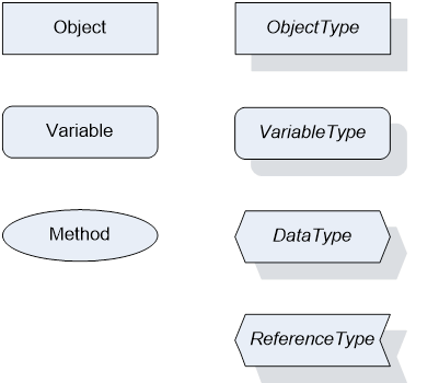
Figure 1 – OPC UA Graphical Notation for NodeClasses
Figure 2 shows the symbols for the ReferenceTypes used in this specification. The Reference symbol is normally pointing from the source Node to the target Node. The only exception is the HasSubType Reference. The most important References like HasComponent, HasProperty, HasTypeDefi nition and HasSubType have special symbols avoiding the name of the Reference. For other ReferenceTypes or derived ReferenceTypes the name of the ReferenceType is used together with the symbol.
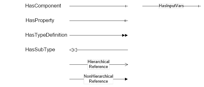
Figure 2 – OPC UA Graphical Notation for References
Figure 3 shows a typical example for the use of the graphical notation. Object_A and Object_B are instances of the ObjectType_Y indicated by the HasTypeDefinition References. The ObjectType_Y is derived from ObjectType_X indicated by the HasSubType Reference. The Object_A has the components Variable_1, Variable_2 and Method_1.
To describe the components of an Object on the ObjectType the same NodeClasses and References are used on the Object and on the ObjectType like for ObjectType_Y in the example. The instance Nodes used to describe an ObjectType are instance declaration Nodes.
To provide more detailed information for a Node, a subset or all Attributes and their values can be added to a graphical symbol.
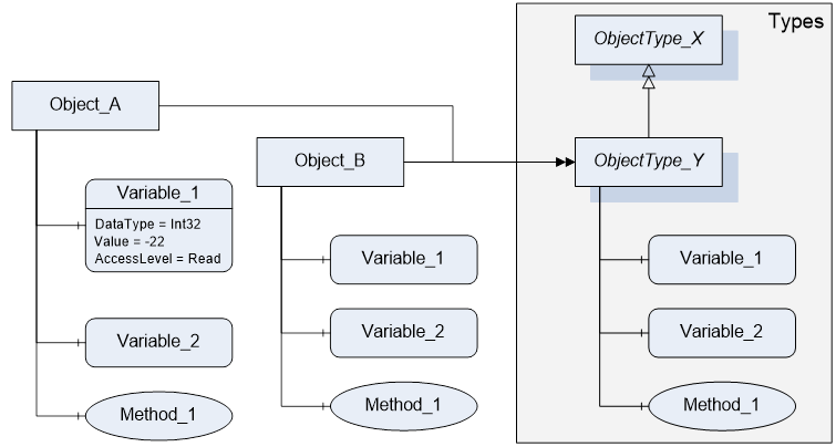
Figure 3 – OPC UA Graphical Notation Example