The typical six-axis industrial robot shown in Figure B.6 normally has 6 power trains for the movement of the 6 axes. Due to the robot hand design, various power trains initiate internal compensation movements. When only the motor of power train 4 is rotating then axes 4, 5, and 6 are moving. When only axis 4 should be moved and axes 5 and 6 should stand still then power trains 5 and 6 must compensate the movement of these axes. Thus a movement of only axis 4 requires rotation of the motors of the power trains 4, 5 and 6. The complete set of references is depicted in Figure B.11.
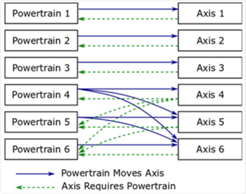
Figure B.11 – Coupling references for a typical six-axis industrial robot.
A power train Moves an axis means that if the motor of only this power train moves then there will be an effect on the position of the axis.
- Power train 1 Moves axis 1
- Power train 2 Moves axis 2
- Power train 3 Moves axis 3
- Power train 4 Moves axis 4, axis 5 and axis 6
- Power train 5 Moves axis 5 and axis 6
- Power train 6 Moves axis 6
Description regarding iv.: When only the motor of power train 4 is moving there is an effect on the position of axis 4, axis 5 and axis 6.
An axis IsMovedBy a power trains means, that actions of these power trains have an influence on the axis position. It is the inverse of the Moves reference.
- Axis 1 IsMovedBy power train 1
- Axis 2 IsMovedBy power train 2
- Axis 3 IsMovedBy power train 3
- Axis 4 IsMovedBy power train 4
- Axis 5 IsMovedBy power train 5 and power train 4
- Axis 6 IsMovedBy power train 6, power train 5 and power train 4
Description regarding vi.: Axis 6 movement is depending on movement from power train 6, power train 5 and power train 4.
An axis Requires the movement of a motor of a power train to position but also other power trains might be involved by this movement to compensation movements of affected axes.
- Axis 1 Requires power train 1
- Axis 2 Requires power train 2
- Axis 3 Requires power train 3
- Axis 4 Requires power train 4, power train 5 and power train 6
- Axis 5 Requires power train 5 and power train 6
- Axis 6 Requires power train 6
Description regarding iv.: When only axis 4 should be moved compensation movements of power train 5 and power train 6 are necessary to ensure a standstill of axis 5 and axis 6.
A power train IsRequiredBy axes means that this power train is active when only the referenced axis should be moved and all other axes should stand still. It is the inverse of the Requires reference.
- Power train 1 IsRequiredBy axis 1
- Power train 2 IsRequiredBy axis 2
- Power train 3 IsRequiredBy axis 3
- Power train 4 IsRequiredBy axis 4
- Power train 5 IsRequiredBy axis 4 and axis 5
- Power train 6 IsRequiredBy axis 4, axis 5 and axis 6
Description regarding vi: Power train 6 participates in positioning of axis 4, axis 5 and axis 6.
A high-payload six-axis industrial robot shown in Figure B.6 can have nine power trains for the movement of the six axes. In this example the axes 1 to 3 are each driven by two power trains with leader-follower configuration.
Figure B.12 shows the use of the HasSlave reference in addition to the power train to axis references.
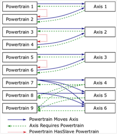
Figure B.12 – Coupling references for a six-axis industrial robot with leader-follower axes
A power train HasSlave a power train means that one power train is the master of a leader-follower-configuration and he references HasSlave to power train which is slave coupled.
HasSlave References:
- Power train 1 HasSlave power train 2
- Power train 3 HasSlave power train 4
- Power train 5 HasSlave power train 6
For this leader-follower configuration the Moves and Requires references :
- Power train 1 Moves axis 1
- Power train 2 Moves axis 1
- Power train 3 Moves axis 2
- Power train 4 Moves axis 2
- Power train 5 Moves axis 3
- Power train 6 Moves axis 3
- Power train 7 Moves axis 4, axis 5 and axis 6
- Power train 8 Moves axis 5 and axis 6
- Power train 9 Moves axis 6
- Axis 1 Requires power train 1 and power train 2
- Axis 2 Requires power train 3 and power train 4
- Axis 3 Requires power train 5 and power train 6
- Axis 4 Requires power train 7, power train 8 and power train 9
- Axis 5 Requires power train 8 and power train 9
- Axis 6 Requires power train 9
For the left motion device in Figure B.10 the References between axes and power trains are shown in Figure B.13.
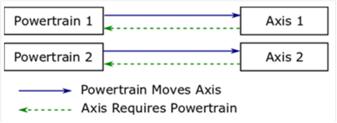
Figure B.13 – Coupling references for a simple linear two-dimensional motion device
Moves References:
Requires References from power train to axis
- Power Train 1 IsRequiredBy axis 1
- Power Train 2 IsRequiredBy axis 2
For the right motion device in Figure B.10 the References between axes and power trains are shown in Figure B.14.
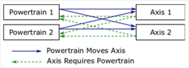
Figure B.14 – Coupling references for linear two-dimensional motion device
Moves References:
Requires References from power train to axis
- Power Train 1 IsRequiredBy axis 1 and axis 2
- Power Train 2 IsRequiredBy axis 1 and axis 2
Figure B.15 describes the usage of DriveType as an instance of a single-slot drive regarding the manipulator showed Figure B.10 on the left side.
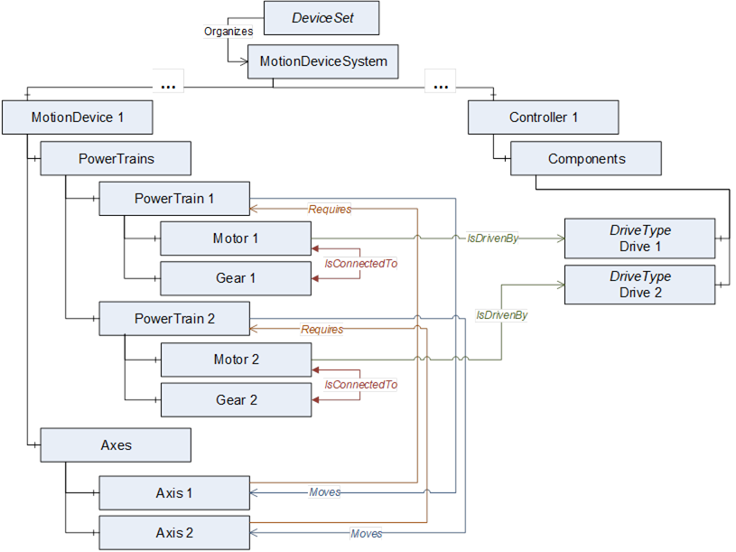
Figure B.15 – IsDrivenby references to DriveType instances
Figure B.16 describes the usage of slots or channels of a multi-slot-drive. The instance of the slot is a vendor specific subtype of BaseObjectType.
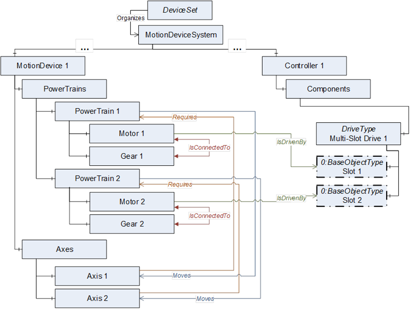
Figure B.16 – IsDrivenby references to vendor specific subtypes of BaseObjectType instances
Figure B.17 describes the usage of DriveType for a multi-slot-drive if deeper information of slot definition is not available.
It is allowed that several instances of MotorType reference IsDrivenBy to one multi-slot-drive.
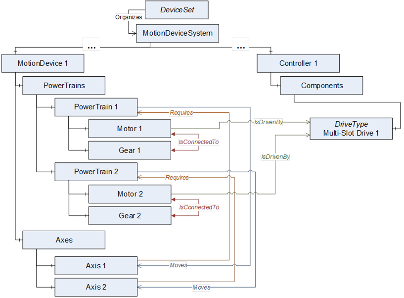
Figure B.17 – IsDrivenBy references to DriveType instances for multi-slot drives w/o slots
Figure B.18 describes the usage with a motor-integrated-drive as one physical device. The instance MyDrive is a vendor specific subtype of BaseObjectType. Identification properties of this physical device shall be defined within the referenced MotorType.
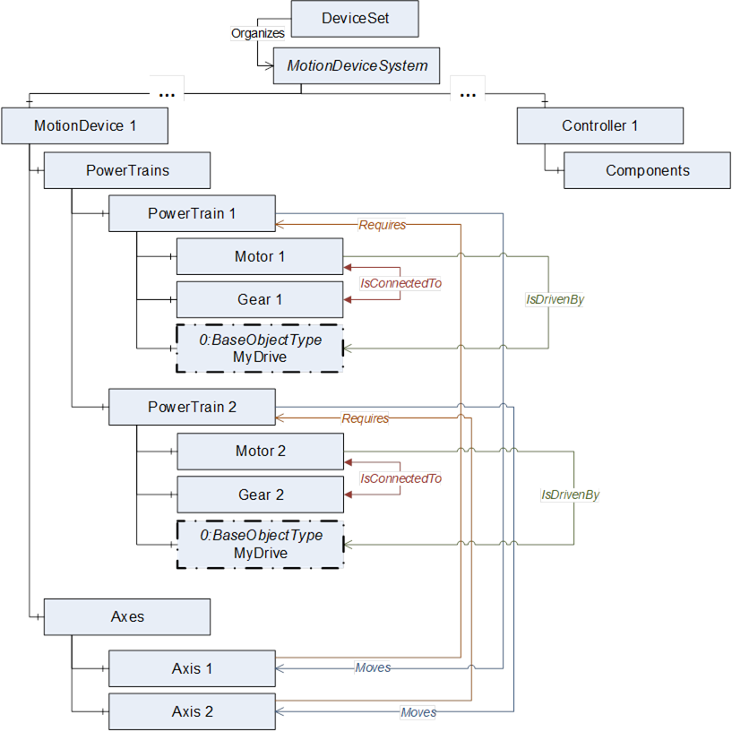
Figure B.18 – IsDrivenBy used with motor-integrated-drives
Figure B.19 describes an example view on a server with the instances of ObjectTypes and references of a six-axis robot with master-slave axis and drive-slots described in Annex B.9.2.
If a leader-follower configuration only has one gear this shall be placed inside the leader-powertrain.
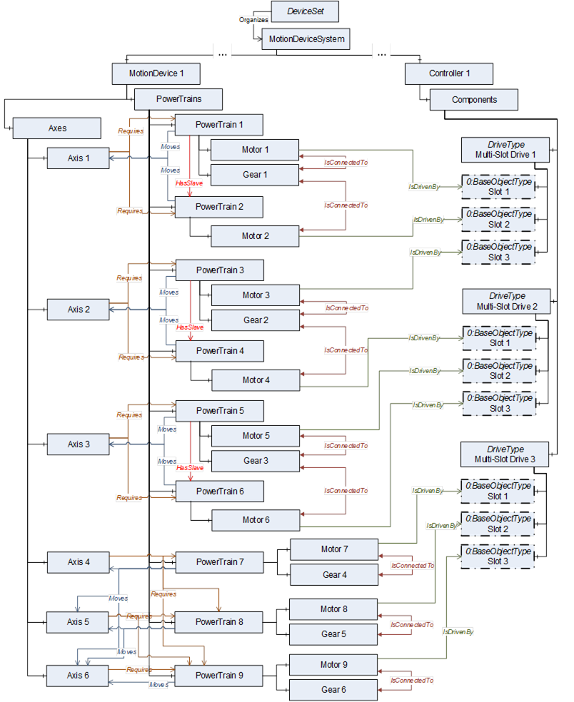
Figure B.19 – View on a six-axis robot with master-slave and drive-slots
Figure B.20 describes an example view on a server with the instances of ObjectTypes and references of a motion device system consisting of a six-axis robot, a linear unit and a turntable which are controlled by one controller.
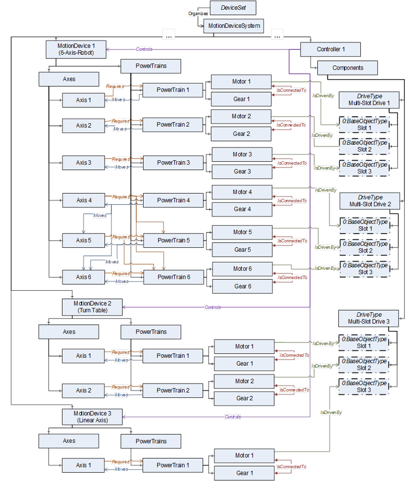
Figure B.20 – View on a motion device system with 3 motion devices controlled by one controller