
5.3.2.2 PROFINET basics
The following chapters give a brief introduction to relevant PROFINET objects and services, which are used in the scope of the OPC UA integration use cases. A detailed definition of these terms can be found in documents from Chapter 2 or several printed documents which are available at www.profinet.com. Nevertheless, the reader of this document should be able to understand the basic PROFINET concepts without knowledge of all the details.
It is important, that the support of some PROFINET information below is not mandatory. Therefore, an optimal usability and features coverage can be achieved with devices which implement a maximum of optional PROFINET features. The requirement of the PROFINET specification is denoted by the capital (PN-M) for mandatory or (PN-O) for optional.
5.3.2.2.1 General
The following information is general for all PROFINET devices.
Device Information (PN-M):
Information that is related to the device with the PROFINET connection to the network. Examples are VendorID, DeviceID, DCP type identification, DNS Name of Station and IP-Address.
Physical Topology (PN-M):
PROFINET can discover the physical topology of installed devices as all devices exchange neighborhood information with the LLDP protocol.
Real Configuration (PN-M):
The real configuration of a PROFINET device contains slots and subslots with modules and submodules plugged in the device independent from any controller connection. Each module/submodule is identified by a module/submodule identification number which must be unique in the scope of one DeviceID. One defined submodule is the representative of the device; one submodule is the representative of a module. Therefore, the submodule is the carrier of all information. Modules and submodules which are installed in the real configuration of the device can be discovered with a PROFINET service. These modules/submodules are the carrier of the asset information.
Expected Configuration (PN-M):
The expected PROFINET configuration is the result of the PROFINET engineering in the configuration tool of the PLC. It contains the devices, modules, submodules which are configured in the engineering system of the PLC, downloaded to the controller and transferred to the devices during startup.
The expected configuration can be read with a defined PROFINET service.
Module Diff Block (PN-M):
The difference between the expected configuration and the real configuration. The reference to the difference is the expected configuration. The module diff block can be read with a defined PROFINET service.
5.3.2.2.2 I&M
PROFINET defines Identification and Maintenance functions since PROFIBUS. As there is a long history, some restrictions in these data are possible. In general, I&M contain defined properties and values to identify the asset more precise as it is possible with IDs and without knowledge of the GSD file.
I&M0 - Electronic Faceplate (PN-M for device, PN-O for Modules):
Version Information of the submodule like serial number, HW-Version and FW-Version. I&M0 data are read-only.
I&M1 - function and location (PN-O):
A unique function and location of the device/submodule as visible strings. I&M1 data must be written by a PROFINET engineering tool or PLC before they can be used. The mapping to marking systems like IEC 81346 are in the responsibility of the user and not in scope of this document.
I&M2 - comment (PN-O):
A comment to the device as visible string. I&M2 data must be written by a PROFINET engineering tool or PLC before they can be used.
I&M3 - installation date (PN-O):
The installation date of the device. I&M3 data must be written by a PROFINET engineering tool or PLC before they can be used.
I&M4 - signature (PN-M and defined for Functional Safety):
If the submodule is configured by an external safety configuration tool, this tool can write a signature of the parameter set in I&M4 data of the submodule. With its signature it is possible to discover differences between a stored parameter set of the engineering tool and a parameter set in the field. I&M4 is only defined for safety devices.
I&M5 - additional information (PN-O)
Offers additional information about a communication module which is part on an IO device. If the device (e.g. a robot) is made by company A, and the communication module by company B, I&M0 contain information about the robot and company A, I&M5 contain information about the communication module and company B.
5.3.2.2.3 Asset management in PROFINET
In addition to the above I&M data which are only bound to the PROFINET address elements slot/subslot, additional end customer requirements for enhanced asset management capabilities are incorporated in the PROFINET specification. Definition of PROFINET asset management objects sometimes use data types already defined by I&M properties. In addition to them other asset management properties are available. Asset information can be bound to slots and subslots to extend information, which cannot be modelled with I&M properties. Moreover, the PROFINET specification defines a level-tree of assets which objects are independent from the slot/subslot addressing scheme.
The following picture shows a possible example of asset management usage in a modular IO device.
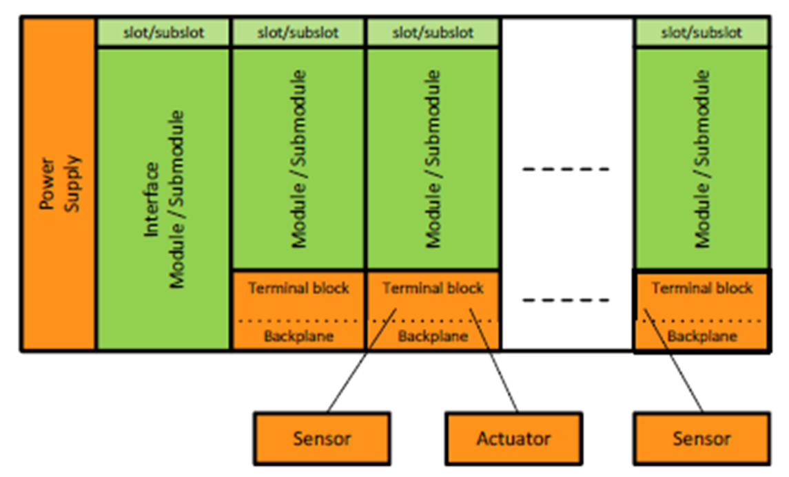
The green elements are the modules and submodules of the station carrying I&M information. Additional asset information like version info of the power supply, terminal blocks or connected sensors and actors can be described by means of asset management objects, which are not directly related to the slot/subslot model.
In addition to this example PROFINET AM can be used to manage all components with loadable software, which can be device or module firmware as well as application programs running on PLCs or robots.
The following asset management objects can be accessed via a defined acyclic read service.
AM_Info:
The scope of the asset information, which can be "full information", "firmware only" or "hardware only".
AM_Location:
The location of an asset within a device as 16 subsequent octets. The location can be either "slot/subslot" to extend I&M information or "level tree" to form hierarchical structures of assets.
IM_UniqueIdentifier:
A 128-bit globally unique identification of the asset created by the manufacturer e.g. by means of ISO/IEC 9834-8:2014.
IM_Annotation:
A manufacturer-specific identifier of the asset such as the asset's name as Unicode string8 with the length of 64 octets.
IM_OrderID:
The order ID of the asset as UnicodeString8 with the length of 64 octets.
AM_SoftwareRevision:
The edition of the software of the asset as UnicodeString8 with 64 octets.
IM_Software_Revision:
Software revision in a special I&M coding of VisibleString[9].
AM_HardwareRevision:
The edition of the hardware of the asset as UnicodeString8 with 64 octets.
IM_Hardware_Revision
The hardware revision in I&M coding.
IM_Serial_Number:
A unique production number of the asset set by the manufacturer as VisibleString16.
AM_DeviceIdentification:
The unique device identification in the address space of an organization like VendorID & DeviceID for PI. Or OUI for IO-Link.
AM_TypeIdentification:
Used to identify the family of the asset and assigned by the manufacturer like "IO controller", "IO device", "IO-Module". Standard and manufacturer specific values are defined in [3].