PROFINET defines a comprehensive diagnostic model. The main focuses of this model are device diagnosis and network diagnosis. Diagnosis scenarios can appear during startup of a plant as well as during operation.
Details of the PROFINET diagnosis concepts are contained in [PN Diag]. The main ideas are summarized in this chapter:
Figure 13 – Diagnosis base model from [PN Diag]
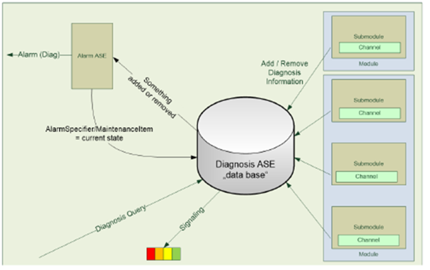
Each IO device maintains a global list of active diagnosis in a database called Diagnosis ASE.
All diagnosis entries are related to a channel of a submodule. The channel can represent a connected sensor or actor as well as the whole submodule. Submodule related diagnosis is marked with the channel number 0x8000.
If some relevant diagnosis or maintenance appears or disappears on a channel, an entry in the diagnosis ASE is added or removed. In this case, the IO controller is informed with diagnosis alarm to have event driven diagnosis information available in the PLC.
A supervisor like an Edge gateway or diagnosis tool can query the diagnosis ASE with a defined PROFINET record. If the ASE contains entries, the query is answered with a list of diagnosis entries. Otherwise the answer is empty to reduce the network load.
Figure 14 – Severity classification of diagnosis from [PN Diag]
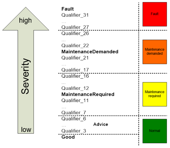
Each channel diagnosis entry contains a severity and a combination of error codes (see Figure 14). Some of these codes are system defined and can be decoded with the help of a general XML file available via PI. Vendor specific and profile specific error codes can be contained in the GSD file of the device.
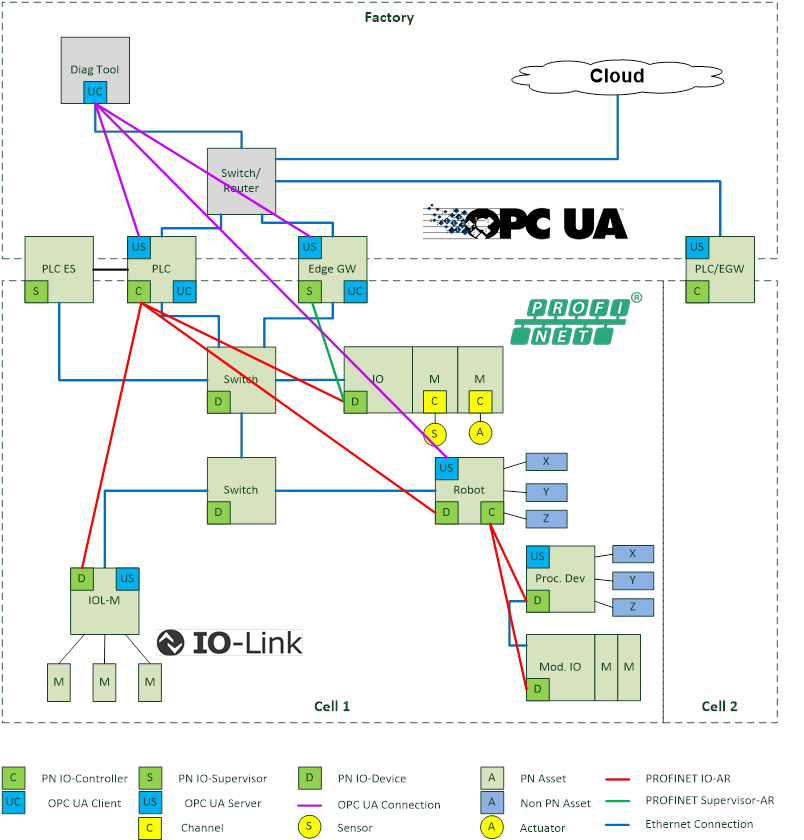
Figure 15 – Architecture of Diagnosis
In the Diagnosis Use-Case a diagnosis tool is connected to a PLC, Edge gateway or the OPC UA Server of the device itself. The integrated OPC UA Server represents the subordinate PROFINET system or devices and their diagnosis state. There are differences in the available diagnosis information in IO controllers, Edge gateways or devices, which must be considered:
- IO controllerAn IO controller may form an OPC UA object model which is based on the expected configuration given by the engineering system. If there is no PROFINET connection (IOAR) between the controller and the device, the controller knows the reason (e.g. Device not found, duplicated names in the network, etc.). IO controllers are informed from the devices with a diagnosis alarm, if anything in the diagnosis ASE has been changed and may determine a time accurate diagnosis state.
- Edge gateways:An Edge gateway may show IO controllers and IO devices which can be discovered during the scanning process. An Edge gateway may determine the expected configuration of the devices with a normative record. The reason for an e.g. unreachable device can be different from an IO controller. Supervisors like Edge Gateways are not informed with an alarm if something in the diagnosis ASE of the devices has been changed. They can be as time accurate as the scanning time is configured.
- Devices:The IO device represents the diagnosis state of the included modules and submodules. In addition it knows if there is a running AR to the IO controller.
Table 17 – Discover differences
|
Goal |
The end user wants to know if there are any differences between the expected configuration given in the ES of an IO controller and installed devices in the field. |
|
Preconditions |
The expected PROFINET configuration is set up in the engineering system of the IO controller, downloaded and activated. The Tag-Function and Tag-Location of I&M1 is configured. |
|
OPC UA Mapping |
In a PLC the information model of the OPC UA Server is build according the expected configuration of the PLCs engineering system. Differences between real and expected configuration are marked at the corresponding submodule of the expected configuration. In an EGW the information model of the OPC UA Server is build according to the scanned devices. Differences to the expected configuration are shown based on module diff block information read from the device. In a device the information model of the OPC UA Server is build according the local configuration. Differences to the expected configuration are shown based on module diff block from the controller AR. PLC is named with its station name and IP-Address. Devices are named with their station name, IP-Address and I&M1 information. |
Table 18 – Discover reachable configuration
|
Goal |
The end user wants to know which devices and their configuration are installed in the field. |
|
Preconditions |
All connected PROFINET systems are configured and running. There can be multiple PLCs in the network visible by an EGW. An EGW or PLC may scan the underlying network continuously with DCP-Identify and PROFINET read services to get all relevant information. For details see [PN TAD]. |
|
OPC UA Mapping |
The information model of the OPC UA Server is build according the scanned devices and their real slot/subslot configuration. This Use-Case should not be implemented in a Device to avoid network load caused by Identify services. |
|
Remarks |
When there is no station name, the MAC address shall be used as BrowseName. If those devices get a correct name, they are visible as a different entity under their station name as the OPC UA browse name shall be unique. |
Table 19 – Connection Diagnosis
|
Goal |
The end user wants to know the state of the PROFINET connections related to the expected configuration of the IO controller |
|
Preconditions |
The expected PROFINET configuration is set up in the engineering system of the IO controller, downloaded and activated. Some ARs between the IO controller and IO devices are established, others cannot be established by e.g. following reasons: Device with configured NoS not found in the network Duplicate NoS detected Duplicate IP-Address detected AR deactivated in PLC application program |
|
OPC UA Mapping |
The connection state of the AR is signaled on the corresponding IO device in the address space of the OPC UA Server. The reason for error is part of the AR. |
Table 20 – Submodule state diagnosis
|
Goal |
The end user wants to know differences between the expected and real configuration related to modules/submodules, their identification as well as other reasons for connection problems. |
|
Preconditions |
The expected PROFINET slot/subslot configuration is set up in the engineering system of the IO controller, downloaded and activated. An EGW may continuously scan the ExpectedConfiguration and ModuleDiffBlock data records from the reachable devices. Some submodules in real configuration differ from the expected. Details see SubmoduleState. Examples: Wrong Submodule No Submodule Substitute Submodule Application Ready Pending Superordinated Locked Locked by IO controller Locked by IO supervisor |
|
OPC UA Mapping |
The difference related to the expected configuration is signaled on the corresponding module/submodule in the address space of the UA Server. The state is shown in a variable with corresponding values of SubmoduleState. |
Table 21 – Device diagnosis or maintenance update
|
Goal |
The end user wants to have information about device/module/submodule/channel related diagnosis or maintenance information. |
|
Preconditions |
All connected PROFINET systems are configured and running. Channel related diagnosis or maintenance (e.g. short circuit) appears on one channel of a real or PDev submodule. An entry in the diagnosis ASE of the IO device is made. The IO controller is informed with a corresponding diagnosis or maintenance alarm. The EGW may scan the underlying network continuously with DCP-Identify and PROFINET read services to the diagnosis ASE. Channel related diagnosis or maintenance (e.g. short circuit) disappears on one channel of a real or PDev submodule. |
|
OPC UA Mapping |
The diagnosis or maintenance is signaled on the corresponding module or submodule in the address space of the OPC UA Server with the following information: ChannelNumber (0x8000 is the whole submodule itself) Severity: fault, maintenance required, maintenance demanded mapped to OPC UA severity classes Error Text from GSDML in current language. Formatted information of ExtChannelAddValue based on GSDML. + Help Text from GSDML.
|
Table 22 – Network diagnosis or maintenance
|
Goal |
The end user wants to have information about the “health” of the physical PROFINET network in the Diagnosis tool in a topological view. |
|
Preconditions |
All connected PROFINET systems are configured and running. PDev related diagnosis or maintenance appear on the network. An EGW or PLC may scan the underlying network continuously with DCP-Identify and PROFINET read services to get all relevant information. The PDev related diagnosis and properties are integrated in the OPC UA address space of the EGW or PLC according to Table 21. |
|
OPC UA Mapping |
A diagnosis tool uses the PDev related information from the OPC UA Server to display a topological view with corresponding details. It is not the responsibility of the OPC UA Server. |
|
Remark |
Display of physical Topology is possible for PROFINET-Devices and PROFINET-switches, but not possible for devices without topology information. |