Figure 6 shows a schematic overview of all parts a PAEFS consists of and how they relate to each other. The representation uses a mixture of a type and instance representation for ease of understanding. Auxiliary objects that represent data structures are not displayed.
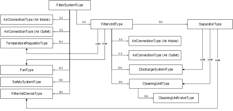
Figure 6 – PAEFS model overview
|
Figure 6 notes |
|
|
0:n |
Indicates that the component can have several instances of this type. There can also be no instances of this type. |
|
1:1 |
Indicates that the component must have exactly one instance of this type. |
|
1:n |
Indicates that the component can have several instances of this type. There must be at least one instance of this type. |
The filter system serves as a root node to which several filter units are attached. A filter unit consists of subcomponents, some of which are optional.
Some components can be shared between filter units and some components are exclusively used by one filter unit. A component which can be used by exactly one filter unit is represented as a child node of the filter unit. A component which is shared by multiple filter units is represented as a child node of the filter system and referenced by its filter units via the Uses reference defined in 10.1.
The shared component temperature regulator is intended to be referenced by one or more filter units. The same applies to the fan component. The discharge system, the cleaning unit and the device for filter aid may be shared by multiple separators. These components should be referenced from the separator by the Uses ReferenceType. Every component may have a safety system that is responsible for monitoring the component. The safety system is referenced by the component via a Uses reference.
Example: Two filter units share a fan. The fan can be used either by one filter unit or by the other filter unit. Both fans are referenced by a Uses reference from the filter unit.
The Uses reference is a many-to-many relation between components which are functionally connected. It serves primarily navigational and organizational purposes.
The filter system and the filter unit must each have exactly two instances of the air connection. Any other component can be instantiated any number of times. The safety system can be used by any main component via the Uses reference. Main components are defined in 10.1.
For the benefit of clarity, the dashed arrows between the safety system and other components in Figure 6 are not drawn.
Depending on the design of the plant, either the filter system or the individual filter units can be regarded as a machine. The following cases are possible:
- The filter system is a machine and the filter units are its components.
- The filter system is not a machine and each filter unit is a machine.
Each machine has methods to turn it on and off. Each machine is listed in the machines folder provided by OPC 40001-1.
The air connection component is an abstract component. It represents a link between two air-carrying systems. It is not a physical component. There are always two air connections, one for the air intake and one for the air outlet. The two air connections are available both on the filter system (total air inflow/outflow) and on the individual filter units (total air distribution).