The IAdministrationType provides the interface to administration variables and methods of the device and is formally defined in Table 16.
Table 16 – IAdministrationType definition
|
Attribute |
Value |
||||
|
BrowseName |
IAdministrationType |
||||
|
IsAbstract |
True |
||||
|
References |
NodeClass |
BrowseName |
DataType |
TypeDefinition |
Other |
|
Subtype of 0:BaseInterfaceType defined in OPC 10000-5, i.e. inheriting the InstanceDeclarations of that Node |
|||||
|
0:HasComponent |
Variable |
DisplayLanguage |
0:LocaleId |
0:BaseDataVariableType |
O |
|
0:HasComponent |
Variable |
DateOfLastChange |
0:DateTime |
0:BaseDataVariableType |
O |
|
0:HasComponent |
Method |
FactoryReset |
Defined in 9.1 |
O |
|
|
Conformance Units |
|||||
|
PA-DIM IAdmin DisplayLanguage |
|||||
|
PA-DIM IAdmin DateOfChange |
|||||
|
PA-DIM IAdmin FactoryReset |
|||||
DisplayLanguage: is the language used for the local display of the device. ABN597#004 defines language or languages set on the display.
DateOfLastChange: ABN604#001 defines parameter indicating the date and time at which one of the device parameters was changed the last time.
FactoryReset: ABN609#002 property the value of which indicates the kind of reset function to be executed. Note: Properties can be variables or methods according IEC 61987 CDD.
The components of IAdministrationType have additional references which are defined in Table 17.
Table 17 – IAdministrationType additional References
|
SourceBrowsePath |
Reference Type |
Is Forward |
TargetBrowsePath |
|
DisplayLanguage |
0:HasDictionaryEntry |
True |
|
|
DateOfLastChange |
0:HasDictionaryEntry |
True |
|
|
FactoryReset |
0:HasDictionaryEntry |
True |
The child Nodes of the IAdministrationType have additional Attribute values defined in Table 18.
Table 18 – IAdministrationType Attribute values for child Nodes
|
BrowsePath |
Value Attribute |
|
DisplayLanguage |
en |
|
DateOfLastChange |
1/1/1601 12:00:00 AM |
The ISignalSetType provides the interface to process variables of the device and is formally defined in Table 19.
Table 19 – ISignalSetType definition
|
Attribute |
Value |
||||
|
BrowseName |
ISignalSetType |
||||
|
IsAbstract |
True |
||||
|
References |
NodeClass |
BrowseName |
DataType |
TypeDefinition |
Other |
|
Subtype of 0:BaseInterfaceType defined in OPC 10000-5, i.e. inheriting the InstanceDeclarations of that Node |
|||||
|
0:HasComponent |
Object |
SignalSet |
|
SignalSetType |
O |
|
Conformance Units |
|||||
|
PA-DIM ISignal |
|||||
SignalSet is a container object for the process variables of the device.
The ICalibrationType provides the interface to calibration variables of the sensor resp. signal and is formally defined in Table 20.
Table 20 – ICalibrationType definition
|
Attribute |
Value |
||||
|
BrowseName |
ICalibrationType |
||||
|
IsAbstract |
True |
||||
|
References |
NodeClass |
BrowseName |
DataType |
TypeDefinition |
Other |
|
Subtype of 0:BaseInterfaceType defined in OPC 10000-5, i.e. inheriting the InstanceDeclarations of that Node |
|||||
|
0:HasProperty |
Variable |
CalibrationTimestamp |
0:DateTime |
0:PropertyType |
O |
|
0:HasComponent |
Variable |
TypeOfCalibration |
0:UInt32 |
0:MultiStateDictionaryEntryDiscreteType |
O |
|
0:HasComponent |
Object |
CalibrationPointSet |
|
CalibrationPointSetType |
O |
|
Conformance Units |
|||||
|
PA-DIM ICalibration |
|||||
|
PA-DIM ICalibration CalibrationTimestamp |
|||||
|
PA-DIM ICalibration TypeOfCalibration |
|||||
|
PA-DIM ICalibration CalibrationPointSet |
|||||
CalibrationTimestamp is defined by IRDI as ABP544#001 which states “point in time when a measurement channel of a device was calibrated”.
TypeOfCalibration is defined by IRDI as ABH609#002 which states “classification of a calibration according to its intended use”.
CalibrationPointSet is a container object for calibration points of the sensor resp. signal.
The components of ICalibrationType have additional references which are defined in Table 21.
Table 21 – ICalibrationType additional References
|
SourceBrowsePath |
Reference Type |
Is Forward |
TargetBrowsePath |
|
CalibrationTimestamp |
0:HasDictionaryEntry |
True |
|
|
TypeOfCalibration |
0:HasDictionaryEntry |
True |
The child Nodes of the ICalibrationType have additional Attribute values defined in Table 22.
Table 22 – ICalibrationType Attribute values for child Nodes
|
BrowsePath |
Value Attribute |
||
|
CalibrationTimestamp |
1/1/1601 12:00:00 AM |
||
|
TypeOfCalibration |
0 |
||
|
ns=3;s=0112/2///61987#ABP732#001 |
||
|
adjustment |
The IConductivityCalibrationType provides the interface to conductivity measurement specific calibration variables of the sensor resp. signal and is formally defined in Table 23.
Table 23 – IConductivityCalibrationType definition
|
Attribute |
Value |
||||
|
BrowseName |
IConductivityCalibrationType |
||||
|
IsAbstract |
True |
||||
|
References |
NodeClass |
BrowseName |
DataType |
TypeDefinition |
Other |
|
Subtype of 0:BaseInterfaceType defined in OPC 10000-5, i.e. inheriting the InstanceDeclarations of that Node |
|||||
|
0:HasComponent |
Variable |
ConductivityCellConstant |
0:Float |
0:AnalogUnitType |
O |
|
Conformance Units |
|||||
|
PA-DIM PhSignalType |
|||||
ConductivityCellConstant is defined by IRDI as ABF161#001 which states “ratio of the distance between the electrodes to the electrode area”.
The components of IConductivityCalibrationType have additional references which are defined in Table 24.
Table 24 – IConductivityCalibrationType additional References
|
SourceBrowsePath |
Reference Type |
Is Forward |
TargetBrowsePath |
|||||
|
ConductivityCellConstant |
0:HasDictionaryEntry |
True |
||||||
|
0:HasDictionaryEntry |
True |
||||||
The child Nodes of the IConductivityCalibrationType have additional Attribute values defined in Table 25.
Table 25 – IConductivityCalibrationType Attribute values for child Nodes
|
BrowsePath |
Value Attribute |
||
|
ConductivityCellConstant |
0.0 |
||
|
NamespaceUri: http://www.opcfoundation.org/UA/units/cdd/IEC62720UnitId: 705744658DisplayName: cm⁻¹Description: reciprocal centimetre |
The IAmperometricCalibrationType provides the interface to amperometric measurement specific calibration variables of the sensor resp. signal and is formally defined in Table 26.
Table 26 – IAmperometricCalibrationType definition
|
Attribute |
Value |
||||
|
BrowseName |
IAmperometricCalibrationType |
||||
|
IsAbstract |
True |
||||
|
References |
NodeClass |
BrowseName |
DataType |
TypeDefinition |
Other |
|
Subtype of 0:BaseInterfaceType defined in OPC 10000-5, i.e. inheriting the InstanceDeclarations of that Node |
|||||
|
0:HasComponent |
Variable |
AmperometricSensorSlope |
0:Float |
0:AnalogUnitType |
O |
|
0:HasComponent |
Variable |
AmperometricSensorZeroPoint |
0:Float |
0:AnalogUnitType |
O |
|
0:HasComponent |
Variable |
AbsoluteAirPressure |
0:Float |
0:AnalogUnitType |
O |
|
0:HasProperty |
Variable |
SensorT90 |
0:Float |
0:PropertyType |
O |
|
Conformance Units |
|||||
|
PA-DIM AmperometricSignalType |
|||||
|
PA-DIM IAmperometricCalibration AbsoluteAirPressure |
|||||
|
PA-DIM IAmperometricCalibration SensorT90 |
|||||
AmperometricSensorSlope is defined by IRDI as ABP572#001 which states “slope of an amperometric sensing element characteristic determined by the last calibration”.
AmperometricSensorZeroPoint is defined by IRDI as ABP573#001 which states “zero point of an amperometric sensing element characteristic determined by the last calibration”.
AbsoluteAirPressure is defined by IRDI as ABP574#001 which states “absolute air pressure under which the last calibration was performed”.
SensorT90 is defined by IRDI as ABP569#001 which states “t90 settling time determined by the last calibration”.
The components of IAmperometricCalibrationType have additional references which are defined in Table 27.
Table 27 – IAmperometricCalibrationType additional References
|
SourceBrowsePath |
Reference Type |
Is Forward |
TargetBrowsePath |
||
|
AmperometricSensorSlope |
0:HasDictionaryEntry |
True |
|||
|
0:HasDictionaryEntry |
True |
|||
|
AmperometricSensorZeroPoint |
0:HasDictionaryEntry |
True |
|||
|
0:HasDictionaryEntry |
True |
|||
|
AbsoluteAirPressure |
0:HasDictionaryEntry |
True |
|||
|
0:HasDictionaryEntry |
True |
|||
|
SensorT90 |
0:HasDictionaryEntry |
True |
The child Nodes of the IAmperometricCalibrationType have additional Attribute values defined in Table 28.
Table 28 – IAmperometricCalibrationType Attribute values for child Nodes
|
BrowsePath |
Value Attribute |
||
|
AmperometricSensorZeroPoint |
0.0 |
||
|
NamespaceUri: http://www.opcfoundation.org/UA/units/cdd/IEC62720UnitId: 705750616DisplayName: pADescription: picoampere |
||
|
AbsoluteAirPressure |
0.0 |
||
|
NamespaceUri: http://www.opcfoundation.org/UA/units/cdd/IEC62720UnitId: 705746519DisplayName: hPaDescription: hectopascal |
||
|
SensorT90 |
0.0 |
The IOpticalFluorescenseQuenchingCalibrationType provides the interface to optical fluorescence quenching measurement specific calibration variables of the sensor resp. signal and is formally defined in Table 29.
Table 29 – IOpticalFluorescenseQuenchingCalibrationType definition
|
Attribute |
Value |
||||
|
BrowseName |
IOpticalFluorescenseQuenchingCalibrationType |
||||
|
IsAbstract |
True |
||||
|
References |
NodeClass |
BrowseName |
DataType |
TypeDefinition |
Other |
|
Subtype of 0:BaseInterfaceType defined in OPC 10000-5, i.e. inheriting the InstanceDeclarations of that Node |
|||||
|
0:HasComponent |
Variable |
OpticalFluorescenseQuenchingSensorSlope |
0:Float |
0:AnalogUnitType |
O |
|
0:HasComponent |
Variable |
OpticalFluorescenseQuenchingSensorZeroPoint |
0:Float |
0:AnalogUnitType |
O |
|
0:HasComponent |
Variable |
AbsoluteAirPressure |
0:Float |
0:AnalogUnitType |
O |
|
0:HasProperty |
Variable |
SensorT90 |
0:Float |
0:PropertyType |
O |
|
Conformance Units |
|||||
|
PA-DIM OpticalFluorescenseQuenchingSignalType |
|||||
|
PA-DIM IOpticalFluorescenseQuenchingCalibration AbsoluteAirPressure |
|||||
|
PA-DIM IOpticalFluorescenseQuenchingCalibration SensorT90 |
|||||
OpticalFluorescenseQuenchingSensorSlope is defined by IRDI as ABP586#001 which states “slope of an optical fluorescence quenching sensing element characteristic determined by the last calibration”.
OpticalFluorescenseQuenchingSensorZeroPoint is defined by IRDI as ABP587#001 which states “zero point of an optical fluorescence quenching sensing element characteristic determined by the last calibration”.
AbsoluteAirPressure is defined by IRDI as ABP574#001 which states “absolute air pressure under which the last calibration was performed”.
SensorT90 is defined by IRDI as ABP569#001 which states “t90 settling time determined by the last calibration”.
The components of IOpticalFluorescenseQuenchingCalibrationType have additional references which are defined in Table 30.
Table 30 – IOpticalFluorescenseQuenchingCalibrationType additional References
|
SourceBrowsePath |
Reference Type |
Is Forward |
TargetBrowsePath |
||
|
OpticalFluorescenseQuenchingSensorSlope |
0:HasDictionaryEntry |
True |
|||
|
0:HasDictionaryEntry |
True |
|||
|
OpticalFluorescenseQuenchingSensorZeroPoint |
0:HasDictionaryEntry |
True |
|||
|
0:HasDictionaryEntry |
True |
|||
|
AbsoluteAirPressure |
0:HasDictionaryEntry |
True |
|||
|
0:HasDictionaryEntry |
True |
|||
|
SensorT90 |
0:HasDictionaryEntry |
True |
The child Nodes of the IOpticalFluorescenseQuenchingCalibrationType have additional Attribute values defined in Table 31.
Table 31 – IOpticalFluorescenseQuenchingCalibrationType Attribute values for child Nodes
|
BrowsePath |
Value Attribute |
||
|
OpticalFluorescenseQuenchingSensorZeroPoint |
0.0 |
||
|
NamespaceUri: http://www.opcfoundation.org/UA/units/cdd/IEC62720UnitId: 705741621DisplayName: µsDescription: microsecond |
||
|
AbsoluteAirPressure |
0.0 |
||
|
NamespaceUri: http://www.opcfoundation.org/UA/units/cdd/IEC62720UnitId: 705746519DisplayName: hPaDescription: hectopascal |
||
|
SensorT90 |
0.0 |
The IGasChromatographCalibrationType provides the interface to gaschromatograph measurement specific calibration variables of the sensor resp. signal and is formally defined in Table 32.
Table 32 – IGasChromatographCalibrationTypedefinition
|
Attribute |
Value |
||||
|
BrowseName |
IGasChromatographCalibrationType |
||||
|
IsAbstract |
True |
||||
|
References |
NodeClass |
BrowseName |
DataType |
TypeDefinition |
Other |
|
Subtype of 0:BaseInterfaceType defined in OPC 10000-5, i.e. inheriting the InstanceDeclarations of that Node |
|||||
|
0:HasProperty |
Variable |
CalibrationRange1ResponseFactor |
0:Float |
0:PropertyType |
O |
|
0:HasComponent |
Variable |
CalibrationRange1LowerRangeValue |
0:Float |
0:AnalogUnitType |
O |
|
0:HasComponent |
Variable |
CalibrationRange1UpperRangeValue |
0:Float |
0:AnalogUnitType |
O |
|
0:HasProperty |
Variable |
CalibrationRange2ResponseFactor |
0:Float |
0:PropertyType |
O |
|
0:HasComponent |
Variable |
CalibrationRange2LowerRangeValue |
0:Float |
0:AnalogUnitType |
O |
|
0:HasComponent |
Variable |
CalibrationRange2UpperRangeValue |
0:Float |
0:AnalogUnitType |
O |
|
0:HasProperty |
Variable |
CalibrationRange3ResponseFactor |
0:Float |
0:PropertyType |
O |
|
0:HasComponent |
Variable |
CalibrationRange3LowerRangeValue |
0:Float |
0:AnalogUnitType |
O |
|
0:HasComponent |
Variable |
CalibrationRange3UpperRangeValue |
0:Float |
0:AnalogUnitType |
O |
|
Conformance Units |
|||||
|
PA-DIM GasChromatograph CalibrationRange1 |
|||||
|
PA-DIM GasChromatograph CalibrationRange2 |
|||||
|
PA-DIM GasChromatograph CalibrationRange3 |
|||||
CalibrationRange1ResponseFactor is defined by IRDI as ABQ024#001 which states "ratio between the concentration of a compound being analysed and the response of the detector to that compound for the calibration range 1".
CalibrationRange1LowerRangeValue is defined by IRDI as ABQ025#001 which states "volume concentration value assigned to the lower range end-value of calibration range 1".
CalibrationRange1UpperRangeValue is defined by IRDI as ABQ026#001 which states "volume concentration value assigned to the upper range end-value of calibration range 1".
CalibrationRange2ResponseFactor is defined by IRDI as ABQ027#001 which states "ratio between the concentration of a compound being analysed and the response of the detector to that compound for the calibration range 2".
CalibrationRange2LowerRangeValue is defined by IRDI as ABQ028#001 which states "volume concentration value assigned to the lower range end-value of calibration range 2".
CalibrationRange2UpperRangeValue is defined by IRDI as ABQ029#001 which states "volume concentration value assigned to the upper range end-value of calibration range 2".
CalibrationRange3ResponseFactor is defined by IRDI as ABQ030#001 which states "ratio between the concentration of a compound being analysed and the response of the detector to that compound for the calibration range 3".
CalibrationRange3LowerRangeValue is defined by IRDI as ABQ031#001 which states "volume concentration value assigned to the lower range end-value of calibration range 3".
CalibrationRange3UpperRangeValue is defined by IRDI as ABQ032#001 which states "volume concentration value assigned to the upper range end-value of calibration range 3".
The components of IGasChromatographCalibrationType have additional references which are defined in Table 33.
Table 33 – IGasChromatographCalibrationType additional References
|
SourceBrowsePath |
Reference Type |
Is Forward |
TargetBrowsePath |
|
CalibrationRange1ResponseFactor |
0:HasDictionaryEntry |
True |
|
|
CalibrationRange1LowerRangeValue |
0:HasDictionaryEntry |
True |
|
|
CalibrationRange1UpperRangeValue |
0:HasDictionaryEntry |
True |
|
|
CalibrationRange2ResponseFactor |
0:HasDictionaryEntry |
True |
|
|
CalibrationRange2LowerRangeValue |
0:HasDictionaryEntry |
True |
|
|
CalibrationRange2UpperRangeValue |
0:HasDictionaryEntry |
True |
|
|
CalibrationRange3ResponseFactor |
0:HasDictionaryEntry |
True |
|
|
CalibrationRange3LowerRangeValue |
0:HasDictionaryEntry |
True |
|
|
CalibrationRange3UpperRangeValue |
0:HasDictionaryEntry |
True |
The child Nodes of the IGasChromatographCalibrationType have additional Attribute values defined in Table 34.
Table 34 – IGasChromatographCalibrationType Attribute values for child Nodes
|
BrowsePath |
Value Attribute |
||
|
CalibrationRange1ResponseFactor |
1.0 |
||
|
CalibrationRange1LowerRangeValue |
0.0 |
||
|
NamespaceUri: http://www.opcfoundation.org/UA/units/cdd/IEC62720 UnitId: 705848917 DisplayName: ppm Description: parts per million |
||
|
CalibrationRange1UpperRangeValue |
100.0 |
||
|
NamespaceUri: http://www.opcfoundation.org/UA/units/cdd/IEC62720 UnitId: 705848917 DisplayName: ppm Description: parts per million |
||
|
CalibrationRange2ResponseFactor |
1.0 |
||
|
CalibrationRange2LowerRangeValue |
0.0 |
||
|
NamespaceUri: http://www.opcfoundation.org/UA/units/cdd/IEC62720 UnitId: 705848917 DisplayName: ppm Description: parts per million |
||
|
CalibrationRange2UpperRangeValue |
100.0 |
||
|
NamespaceUri: http://www.opcfoundation.org/UA/units/cdd/IEC62720 UnitId: 705848917 DisplayName: ppm Description: parts per million |
||
|
CalibrationRange3ResponseFactor |
1.0 |
||
|
CalibrationRange3LowerRangeValue |
0.0 |
||
|
NamespaceUri: http://www.opcfoundation.org/UA/units/cdd/IEC62720 UnitId: 705848917 DisplayName: ppm Description: parts per million |
||
|
CalibrationRange3UpperRangeValue |
100.0 |
||
|
NamespaceUri: http://www.opcfoundation.org/UA/units/cdd/IEC62720 UnitId: 705848917 DisplayName: ppm Description: parts per million |
The IPhCalibrationType provides the interface to pH measurement specific calibration variables of the sensor resp. signal and is formally defined in .
Table 35 – IPhCalibrationType definition
|
Attribute |
Value |
||||
|
BrowseName |
IPhCalibrationType |
||||
|
IsAbstract |
True |
||||
|
References |
NodeClass |
BrowseName |
DataType |
TypeDefinition |
Other |
|
Subtype of 0:BaseInterfaceType defined in OPC 10000-5, i.e. inheriting the InstanceDeclarations of that Node |
|||||
|
0:HasComponent |
Variable |
SensorSlope |
0:Float |
0:AnalogUnitType |
O |
|
0:HasComponent |
Variable |
SensorAsymmetryPotential |
0:Float |
0:AnalogUnitType |
O |
|
0:HasProperty |
Variable |
SensorT90 |
0:Float |
0:PropertyType |
O |
|
Conformance Units |
|||||
|
PA-DIM PhSignalType |
|||||
|
PA-DIM IPhCalibration SensorT90 |
|||||
SensorSlope is defined by IRDI as ABP567#001 which states “slope of a pH sensing element characteristic, expressed as the voltage change of the pH sensor per pH value, determined by the last calibration”.
SensorAsymmetryPotential is defined by IRDI as ABP568#001 which states “asymmetry potential of a pH sensing element characteristic determined by the last calibration”.
SensorT90is defined by IRDI as ABP569#001 which states “t90 settling time determined by the last calibration”.
The components of IPhCalibrationType have additional references which are defined in Table 36.
Table 36 – IPhCalibrationType additional References
|
SourceBrowsePath |
Reference Type |
Is Forward |
TargetBrowsePath |
||
|
SensorSlope |
0:HasDictionaryEntry |
True |
|||
|
0:HasDictionaryEntry |
True |
|||
|
SensorAsymmetryPotential |
0:HasDictionaryEntry |
True |
|||
|
0:HasDictionaryEntry |
True |
|||
|
SensorT90 |
0:HasDictionaryEntry |
True |
The child Nodes of the IPhCalibrationType have additional Attribute values defined in Table 37.
Table 37 – IPhCalibrationType Attribute values for child Nodes
|
BrowsePath |
Value Attribute |
||
|
SensorSlope |
0.0 |
||
|
NamespaceUri: http://www.opcfoundation.org/UA/units/cdd/IEC62720UnitId: 705749524DisplayName: mV Description: millivolt |
||
|
SensorAsymmetryPotential |
0.0 |
||
|
NamespaceUri: http://www.opcfoundation.org/UA/units/cdd/IEC62720UnitId: 705749524 DisplayName: mV Description: millivolt |
||
|
SensorT90 |
0.0 |
The IGeneralDeviceConditionSetType provides the interface to condition variables of the device and its components and is formally defined in Table 38.
Table 38 – IGeneralDeviceConditionSetType definition
|
Attribute |
Value |
||||
|
BrowseName |
IGeneralDeviceConditionSetType |
||||
|
IsAbstract |
True |
||||
|
References |
NodeClass |
BrowseName |
DataType |
TypeDefinition |
Other |
|
Subtype of 0:BaseInterfaceType defined in OPC 10000-5, i.e. inheriting the InstanceDeclarations of that Node |
|||||
|
0:HasComponent |
Object |
GeneralDeviceConditions |
|
GeneralDeviceConditionSetType |
O |
|
0:HasComponent |
Object |
DeviceComponentConditions |
|
0:BaseObjectType |
O |
|
Conformance Units |
|||||
|
PA-DIM IGeneralDeviceConditionSet |
|||||
|
PA-DIM IGeneralDeviceConditionSet DeviceComponentConditions |
|||||
GeneralDeviceConditions is a container object for general condition variables of the device.
DeviceComponentConditions is a container object for condition variables of the device components.
Table 39 – IGeneralDeviceConditionSetType additional subcomponents
|
BrowsePath |
References |
NodeClass |
BrowseName |
DataType |
TypeDefinition |
Other |
|
DeviceComponentConditions |
0:HasComponent |
Object |
<DeviceComponentIdentifier> |
|
GeneralDeviceConditionSetType |
OP |
<DeviceComponentIdentifier> is an optional placeholder for an object containing the condition variables related to a specific device component.
The ITocDeviceConditionSetType provides the interface to TOC device specific condition variables and is formally defined in Table 40.
Table 40 – ITocDeviceConditionSetType definition
|
Attribute |
Value |
||||
|
BrowseName |
ITocDeviceConditionSetType |
||||
|
IsAbstract |
True |
||||
|
References |
NodeClass |
BrowseName |
DataType |
TypeDefinition |
Other |
|
Subtype of 0:BaseInterfaceType defined in OPC 10000-5, i.e. inheriting the InstanceDeclarations of that Node |
|||||
|
0:HasComponent |
Variable |
CarrierGasVolumeFlow |
0:Float |
0:AnalogUnitType |
O |
|
0:HasComponent |
Variable |
CarrierGasGaugePressure |
0:Float |
0:AnalogUnitType |
O |
|
0:HasComponent |
Variable |
ReactorTemperature |
0:Float |
0:AnalogUnitType |
O |
|
0:HasComponent |
Variable |
SampleWaterVolumeFlow |
0:Float |
0:AnalogUnitType |
O |
|
0:HasComponent |
Variable |
ReferenceInjectionVolume |
0:Float |
0:AnalogUnitType |
O |
|
0:HasComponent |
Variable |
ActualInjectedVolume |
0:Float |
0:AnalogUnitType |
O |
|
0:HasComponent |
Variable |
CoolerTemperature |
0:Float |
0:AnalogUnitType |
O |
|
Conformance Units |
|||||
|
PA-DIM TocAnalyserType |
|||||
|
PA-DIM TocAnalyserType CarrierGasGaugePressure |
|||||
|
PA-DIM TocAnalyserType SampleWaterVolumeFlow |
|||||
|
PA-DIM TocAnalyserType ActualInjectedVolume |
|||||
CarrierGasVolumeFlow is defined by IRDI as ABP558#001 which states “volume flow of the auxiliary (compressed air) gas supply”.
CarrierGasGaugePressure is defined by IRDI as ABP559#001 which states “overpressure of the auxiliary (compressed air) gas supply in the system due to flow resistance within the complete analytical system”.
ReactorTemperature is defined by IRDI as ABP554#001 which states “measured temperature of a high temperature combustion system”.
SampleWaterVolumeFlow is defined by IRDI as ABP561#001 which states “volume flow of a liquid sample inside the device”.
ReferenceInjectionVolume is defined by IRDI as ABP563#001 which states “volume of liquid that should be injected by the injection system”.
ActualInjectedVolume is defined by IRDI as ABP564#001 which states “volume of liquid that has been injected by the injection system”.
CoolerTemperature is defined by IRDI as ABP555#001 which states “measured temperature of the gas cooler”.
The components of ITocDeviceConditionSetType have additional references which are defined in Table 41.
Table 41 – ITocDeviceConditionSetType additional References
|
SourceBrowsePath |
Reference Type |
Is Forward |
TargetBrowsePath |
||
|
CarrierGasVolumeFlow |
0:HasDictionaryEntry |
True |
|||
|
0:HasDictionaryEntry |
True |
|||
|
CarrierGasGaugePressure |
0:HasDictionaryEntry |
True |
|||
|
0:HasDictionaryEntry |
True |
|||
|
ReactorTemperature |
0:HasDictionaryEntry |
True |
|||
|
0:HasDictionaryEntry |
True |
|||
|
SampleWaterVolumeFlow |
0:HasDictionaryEntry |
True |
|||
|
0:HasDictionaryEntry |
True |
|||
|
ReferenceInjectionVolume |
0:HasDictionaryEntry |
True |
|||
|
0:HasDictionaryEntry |
True |
|||
|
ActualInjectedVolume |
0:HasDictionaryEntry |
True |
|||
|
0:HasDictionaryEntry |
True |
|||
|
CoolerTemperature |
0:HasDictionaryEntry |
True |
|||
|
0:HasDictionaryEntry |
True |
The child Nodes of the ITocDeviceConditionSetType have additional Attribute values defined in Table 42.
Table 42 – ITocDeviceConditionSetType Attribute values for child Nodes
|
BrowsePath |
Value Attribute |
||
|
CarrierGasVolumeFlow |
0.0 |
||
|
NamespaceUri: http://www.opcfoundation.org/UA/units/cdd/IEC62720UnitId: 705747637DisplayName: l/hDescription: litre per hour |
||
|
CarrierGasGaugePressure |
0.0 |
||
|
NamespaceUri: http://www.opcfoundation.org/UA/units/cdd/IEC62720UnitId: 705749552DisplayName: mbarDescription: millibar |
||
|
ReactorTemperature |
0.0 |
||
|
NamespaceUri: http://www.opcfoundation.org/UA/units/cdd/IEC62720UnitId: 705741427 DisplayName: °CDescription: degree Celsius |
||
|
SampleWaterVolumeFlow |
0.0 |
||
|
NamespaceUri: http://www.opcfoundation.org/UA/units/cdd/IEC62720UnitId: 705749685DisplayName: ml/min Description: millilitre per minute |
||
|
ReferenceInjectionVolume |
0.0 |
||
|
NamespaceUri: http://www.opcfoundation.org/UA/units/cdd/IEC62720 UnitId: 705749652DisplayName: ml Description: millilitre |
||
|
ActualInjectedVolume |
0.0 |
||
|
NamespaceUri: http://www.opcfoundation.org/UA/units/cdd/IEC62720 UnitId: 705749652DisplayName: ml Description: millilitre |
||
|
CoolerTemperature |
0.0 |
||
|
NamespaceUri: http://www.opcfoundation.org/UA/units/cdd/IEC62720UnitId: 705741427 DisplayName: °CDescription: degree Celsius |
The IFlameIonisationDeviceConditionSetType provides the interface to FID specific condition variables and is formally defined in Table 43.
Table 43 – IFlameIonisationDeviceConditionSetType definition
|
Attribute |
Value |
||||
|
BrowseName |
IFlameIonisationDeviceConditionSetType |
||||
|
IsAbstract |
True |
||||
|
References |
NodeClass |
BrowseName |
DataType |
TypeDefinition |
Other |
|
Subtype of 0:BaseInterfaceType defined in OPC 10000-5, i.e. inheriting the InstanceDeclarations of that Node |
|||||
|
0:HasComponent |
Variable |
CatalystTemperature |
0:Float |
0:AnalogUnitType |
O |
|
0:HasComponent |
Variable |
FuelGasPressure |
0:Float |
0:AnalogUnitType |
O |
|
0:HasComponent |
Variable |
CombustionAirPressure |
0:Float |
0:AnalogUnitType |
O |
|
0:HasComponent |
Variable |
BlockTemperature |
0:Float |
0:AnalogUnitType |
O |
|
Conformance Units |
|||||
|
PA-DIM FlameIonisationDetectorType CatalystTemperature |
|||||
|
PA-DIM FlameIonisationDetectorType FuelGasPressure |
|||||
|
PA-DIM FlameIonisationDetectorType CombustionAirPressure |
|||||
|
PA-DIM FlameIonisationDetectorType BlockTemperature |
|||||
CatalystTemperature is defined by IRDI as ABP576#001 which states “measured temperature of a catalyst”.
FuelGasPressure is defined by IRDI as ABP578#001 which states “measured absolute pressure of the fuel gas”.
CombustionAirPressure is defined by IRDI as ABP579#001 which states “measured absolute pressure of the combustion air”.
BlockTemperature is defined by IRDI as ABP577#001 which states “measured temperature of a flame ionisation detector block”.
The components of IFlameIonisationDeviceConditionSetType have additional references which are defined in Table 44.
Table 44 – IFlameIonisationDeviceConditionSetType additional References
|
SourceBrowsePath |
Reference Type |
Is Forward |
TargetBrowsePath |
||
|
CatalystTemperature |
0:HasDictionaryEntry |
True |
|||
|
0:HasDictionaryEntry |
True |
|||
|
FuelGasPressure |
0:HasDictionaryEntry |
True |
|||
|
0:HasDictionaryEntry |
True |
|||
|
CombustionAirPressure |
0:HasDictionaryEntry |
True |
|||
|
0:HasDictionaryEntry |
True |
|||
|
BlockTemperature |
0:HasDictionaryEntry |
True |
|||
|
0:HasDictionaryEntry |
True |
The child Nodes of the IFlameIonisationDeviceConditionSetType have additional Attribute values defined in Table 45.
Table 45 – IFlameIonisationDeviceConditionSetType Attribute values for child Nodes
|
BrowsePath |
Value Attribute |
||
|
CatalystTemperature |
0.0 |
||
|
NamespaceUri: http://www.opcfoundation.org/UA/units/cdd/IEC62720UnitId: 705741427 DisplayName: °CDescription: degree Celsius |
||
|
FuelGasPressure |
0.0 |
||
|
NamespaceUri: http://www.opcfoundation.org/UA/units/cdd/IEC62720UnitId: 705749552DisplayName: mbarDescription: millibar |
||
|
CombustionAirPressure |
0.0 |
||
|
NamespaceUri: http://www.opcfoundation.org/UA/units/cdd/IEC62720UnitId: 705749552DisplayName: mbarDescription: millibar |
||
|
BlockTemperature |
0.0 |
||
|
NamespaceUri: http://www.opcfoundation.org/UA/units/cdd/IEC62720UnitId: 705741427 DisplayName: °CDescription: degree Celsius |
The IGasChromatographDeviceConditionSetType provides the interface to gas chromatograph device specific condition variables and is formally defined in Table 46
Table 46 – IGasChromatographDeviceConditionSetType definition
|
Attribute |
Value |
||||
|
BrowseName |
IGasChromatographDeviceConditionSetType |
||||
|
IsAbstract |
True |
||||
|
References |
NodeClass |
BrowseName |
DataType |
TypeDefinition |
Other |
|
Subtype of 0:BaseInterfaceType defined in OPC 10000-5, i.e. inheriting the InstanceDeclarations of that Node |
|||||
|
0:HasProperty |
Variable |
ValveName |
0:LocalizedText[] |
0:PropertyType |
O |
|
0:HasProperty |
Variable |
ValveSwitchingCyclesCounter |
0:UInt32[] |
0:PropertyType |
O |
|
0:HasComponent |
Variable |
TotalAreaMeasuredPeaks |
0:Float |
0:AnalogUnitType |
O |
|
0:HasComponent |
Variable |
BaselineNoise |
0:Float |
0:AnalogUnitType |
O |
|
Conformance Units |
|||||
|
PA-DIM GasChromatographType |
|||||
|
PA-DIM GasChromatographType Valve |
|||||
|
PA-DIM GasChromatographType TotalAreaMeasuredPeaks |
|||||
|
PA-DIM GasChromatographType BaselineNoise |
|||||
ValveName is defined by IRDI as ABQ046#001 which states “name of the valve”.
ValveSwitchingCyclesCounter is defined by IRDI as ABQ007#001 which states “number of opening or closing operations of a valve”.
TotalAreaMeasuredPeaks is defined by IRDI as ABQ043#001 which states “integral of the area under the output peaks of all chromatogram substance signals in units defined by the manufacturer”.
BaselineNoise is defined by IRDI as ABQ036#001 which states “short-term variation of the baseline from a straight line caused by electric signal fluctuations from the detector”.
The components of IGasChromatographDeviceConditionSetType have additional references which are defined in Table 48.
Table 47 – IGasChromatographDeviceConditionSetType additional References
|
SourceBrowsePath |
Reference Type |
Is Forward |
TargetBrowsePath |
|
ValveName |
0:HasDictionaryEntry |
True |
|
|
ValveSwitchingCyclesCounter |
0:HasDictionaryEntry |
True |
|
|
TotalAreaMeasuredPeaks |
0:HasDictionaryEntry |
True |
|
|
BaselineNoise |
0:HasDictionaryEntry |
True |
The child Nodes of the IGasChromatographDeviceConditionSetType have additional Attribute values defined in Table 48.
Table 48 – IGasChromatographDeviceConditionSetType Attribute values for child Nodes
|
BrowsePath |
Value Attribute |
||
|
TotalAreaMeasuredPeaks |
0.0 |
||
|
NamespaceUri: http://www.opcfoundation.org/UA/units/cdd/IEC62720 UnitId: 705741328 DisplayName: % Description: percent |
||
|
BaselineNoise |
0.0 |
||
|
NamespaceUri: http://www.opcfoundation.org/UA/units/cdd/IEC62720UnitId: 705749524 DisplayName: mVDescription: millivolt |
The IFtnirOrFtirDeviceConditionSetType provides the interface to Fourier Transform Near-Infrared Spectroscopy or Fourier Transform Infrared Spectroscopy device specific condition variables and is formally defined in Table 49.
Table 49 – IFtnirOrFtirDeviceConditionSetType definition
|
Attribute |
Value |
||||
|
BrowseName |
IFtnirOrFtirDeviceConditionSetType |
||||
|
IsAbstract |
True |
||||
|
References |
NodeClass |
BrowseName |
DataType |
TypeDefinition |
Other |
|
Subtype of 0:BaseInterfaceType defined in OPC 10000-5, i.e. inheriting the InstanceDeclarations of that Node |
|||||
|
0:HasProperty |
Variable |
Watchdog |
0:Boolean |
0:PropertyType |
O |
|
0:HasProperty |
Variable |
RemainingDataStorageCapacity |
0:Float |
0:PropertyType |
O |
|
Conformance Units |
|||||
|
PA-DIM FtnirOrFtirSpectrometerType |
|||||
|
PA-DIM FtnirOrFtirSpectrometerType Watchdog |
|||||
|
PA-DIM FtnirOrFtirSpectrometerType RemainingDataStorageCapacity |
|||||
Watchdog is defined by IRDI as ABP996#002 which states “existence of a function for failure detection of installed hardware and software”
RemainingDataStorageCapacity is defined by IRDI as ABQ039#001 which states “amount of memory remaining for storage of device data, measured in terabytes”.
The components of IFtnirOrFtirDeviceConditionSetType have additional references which are defined in Table 50.
Table 50 – IFtnirOrFtirDeviceConditionSetType additional References
|
SourceBrowsePath |
Reference Type |
Is Forward |
TargetBrowsePath |
|
Watchdog |
0:HasDictionaryEntry |
True |
|
|
RemainingDataStorageCapacity |
0:HasDictionaryEntry |
True |
The child Nodes of the IFtnirOrFtirDeviceConditionSetType have additional Attribute values defined in Table 51.
Table 51 – IFtnirOrFtirDeviceConditionSetType Attribute values for child Nodes
|
BrowsePath |
Value Attribute |
|
RemainingDataStorageCapacity |
0.0 |
The IDiodeArrayDeviceConditionSetType provides the interface to Diode array spectrometer device specific condition variables and is formally defined in Table 52.
Table 52 – IDiodeArrayDeviceConditionSetType definition
|
Attribute |
Value |
||||
|
BrowseName |
IDiodeArrayDeviceConditionSetType |
||||
|
IsAbstract |
True |
||||
|
References |
NodeClass |
BrowseName |
DataType |
TypeDefinition |
Other |
|
Subtype of 0:BaseInterfaceType defined in OPC 10000-5, i.e. inheriting the InstanceDeclarations of that Node |
|||||
|
0:HasProperty |
Variable |
Watchdog |
0:Boolean |
0:PropertyType |
O |
|
0:HasProperty |
Variable |
RemainingDataStorageCapacity |
0:Float |
0:PropertyType |
O |
|
Conformance Units |
|||||
|
PA-DIM DiodeArraySpectrometerType |
|||||
|
PA-DIM DiodeArraySpectrometerType Watchdog |
|||||
|
PA-DIM DiodeArraySpectrometerType RemainingDataStorageCapacity |
|||||
|
|
|||||
Watchdog is defined by IRDI as ABP996#002 which states “existence of a function for failure detection of installed hardware and software”
RemainingDataStorageCapacity is defined by IRDI as ABQ039#001 which states “amount of memory remaining for storage of device data, measured in terabytes”.
The components of IDiodeArrayDeviceConditionSetType have additional references which are defined in Table 53.
Table 53 – IDiodeArrayDeviceConditionSetType additional References
|
SourceBrowsePath |
Reference Type |
Is Forward |
TargetBrowsePath |
|
Watchdog |
0:HasDictionaryEntry |
True |
|
|
RemainingDataStorageCapacity |
0:HasDictionaryEntry |
True |
The child Nodes of the IDiodeArrayDeviceConditionSetType have additional Attribute values defined in Table 54.
Table 54 – IDiodeArrayDeviceConditionSetType Attribute values for child Nodes
|
BrowsePath |
Value Attribute |
|
RemainingDataStorageCapacity |
0.0 |
The IRamanDeviceConditionSetType provides the interface to Raman spectrometer device specific condition variables and is formally defined in Table 55.
Table 55 – IRamanDeviceConditionSetType definition
|
Attribute |
Value |
||||
|
BrowseName |
IRamanDeviceConditionSetType |
||||
|
IsAbstract |
True |
||||
|
References |
NodeClass |
BrowseName |
DataType |
TypeDefinition |
Other |
|
Subtype of 0:BaseInterfaceType defined in OPC 10000-5, i.e. inheriting the InstanceDeclarations of that Node |
|||||
|
0:HasProperty |
Variable |
Watchdog |
0:Boolean |
0:PropertyType |
O |
|
0:HasProperty |
Variable |
RemainingDataStorageCapacity |
0:Float |
0:PropertyType |
O |
|
Conformance Units |
|||||
|
PA-DIM RamanSpectrometerType |
|||||
|
PA-DIM RamanSpectrometerType Watchdog |
|||||
|
PA-DIM RamanSpectrometerType RemainingDataStorageCapacity |
|||||
|
|
|||||
Watchdog is defined by IRDI as ABP996#002 which states “existence of a function for failure detection of installed hardware and software”
RemainingDataStorageCapacity is defined by IRDI as ABQ039#001 which states “amount of memory remaining for storage of device data, measured in terabytes”.
The components of IRamanDeviceConditionSetType have additional references which are defined in Table 56.
Table 56 – IRamanDeviceConditionSetType additional References
|
SourceBrowsePath |
Reference Type |
Is Forward |
TargetBrowsePath |
|
Watchdog |
0:HasDictionaryEntry |
True |
|
|
RemainingDataStorageCapacity |
0:HasDictionaryEntry |
True |
The child Nodes of the IRamanDeviceConditionSetType have additional Attribute values defined in Table 57.
Table 57 – IRamanDeviceConditionSetType Attribute values for child Nodes
|
BrowsePath |
Value Attribute |
|
RemainingDataStorageCapacity |
0.0 |
The INonDispersiveInfraredSignalConditionSetType provides the interface to NDIR measurement signal specific condition variables and is formally defined in Table 58.
Table 58 – INonDispersiveInfraredSignalConditionSetType definition
|
Attribute |
Value |
||||
|
BrowseName |
INonDispersiveInfraredSignalConditionSetType |
||||
|
IsAbstract |
True |
||||
|
References |
NodeClass |
BrowseName |
DataType |
TypeDefinition |
Other |
|
Subtype of 0:BaseInterfaceType defined in OPC 10000-5, i.e. inheriting the InstanceDeclarations of that Node |
|||||
|
0:HasComponent |
Variable |
ChopperFrequencyDeviation |
0:Float |
0:BaseAnalogType |
O |
|
0:HasComponent |
Variable |
AbsoluteSampleGasPressure |
0:Float |
0:AnalogUnitType |
O |
|
0:HasComponent |
Variable |
SampleCellTemperature |
0:Float |
0:AnalogUnitType |
O |
|
0:HasProperty |
Variable |
SourceResidualLife |
0:Float |
0:PropertyType |
O |
|
Conformance Units |
|||||
|
PA-DIM NonDispersiveInfraredSignalType ChopperFrequencyDeviation |
|||||
|
PA-DIM NonDispersiveInfraredSignalType |
|||||
|
PA-DIM NonDispersiveInfraredSignalType AbsoluteSampleGasPressure |
|||||
ChopperFrequencyDeviation is defined by IRDI as ABP553#001 which states “relative change in the chopper frequency of a detector during a measurement”.
AbsoluteSampleGasPressure is defined by IRDI as ABP560#001 which states “absolute pressure of sample gas inside a detection system”.
SampleCellTemperature is defined by IRDI as ABP556#001 which states “measured temperature of the sample cell”.
SourceResidualLife is defined by IRDI as ABP552#001 which states “degradation of a radiation source expressed as a value between 1 (good) and 0 (bad)”.
The components of INonDispersiveInfraredSignalConditionSetType have additional references which are defined in Table 59.
Table 59 – INonDispersiveInfraredSignalConditionSetType additional References
|
SourceBrowsePath |
Reference Type |
Is Forward |
TargetBrowsePath |
||
|
ChopperFrequencyDeviation |
0:HasDictionaryEntry |
True |
|||
|
0:HasDictionaryEntry |
True |
|||
|
AbsoluteSampleGasPressure |
0:HasDictionaryEntry |
True |
|||
|
0:HasDictionaryEntry |
True |
|||
|
SampleCellTemperature |
0:HasDictionaryEntry |
True |
|||
|
0:HasDictionaryEntry |
True |
|||
|
SourceResidualLife |
0:HasDictionaryEntry |
True |
The child Nodes of the INonDispersiveInfraredSignalConditionSetType have additional Attribute values defined in Table 60.
Table 60 – INonDispersiveInfraredSignalConditionSetType Attribute values for child Nodes
|
BrowsePath |
Value Attribute |
||
|
ChopperFrequencyDeviation |
0.0 |
||
|
NamespaceUri: http://www.opcfoundation.org/UA/units/cdd/IEC62720 UnitId: 705741328 DisplayName: % Description: percent |
||
|
AbsoluteSampleGasPressure |
0.0 |
||
|
NamespaceUri: http://www.opcfoundation.org/UA/units/cdd/IEC62720UnitId: 705749552DisplayName: mbarDescription: millibar |
||
|
SampleCellTemperature |
0.0 |
||
|
NamespaceUri: http://www.opcfoundation.org/UA/units/cdd/IEC62720UnitId: 705741427 DisplayName: °CDescription: degree Celsius |
||
|
SourceResidualLife |
1.0 |
The ITocSignalConditionSetType provides the interface to TOC measurement signal specific condition variables and is formally defined in Table 61.
Table 61 – ITocSignalConditionSetType definition
|
Attribute |
Value |
||||
|
BrowseName |
ITocSignalConditionSetType |
||||
|
IsAbstract |
True |
||||
|
References |
NodeClass |
BrowseName |
DataType |
TypeDefinition |
Other |
|
Subtype of 0:BaseInterfaceType defined in OPC 10000-5, i.e. inheriting the InstanceDeclarations of that Node |
|||||
|
0:HasComponent |
Variable |
ChopperFrequencyDeviation |
0:Float |
0:BaseAnalogType |
O |
|
0:HasComponent |
Variable |
RelativeReagentLevel |
0:Float{Any} |
0:AnalogUnitType |
O |
|
0:HasComponent |
Variable |
SampleCellTemperature |
0:Float |
0:AnalogUnitType |
O |
|
0:HasComponent |
Variable |
DetectorZeroSignal |
0:Float |
0:AnalogUnitType |
O |
|
0:HasProperty |
Variable |
SourceResidualLife |
0:Float |
0:PropertyType |
O |
|
0:HasComponent |
Variable |
AbsoluteSampleGasPressure |
0:Float |
0:AnalogUnitType |
O |
|
0:HasComponent |
Variable |
SampleGasVolumeFlow |
0:Float |
0:AnalogUnitType |
O |
|
Conformance Units |
|||||
|
PA-DIM TocSignalType |
|||||
|
PA-DIM TocSignalType ChopperFrequencyDeviation |
|||||
|
PA-DIM TocSignalType RelativeReagentLevel |
|||||
|
PA-DIM TocSignalType AbsoluteSampleGasPressure |
|||||
|
PA-DIM TocSignalType SampleGasVolumeFlow |
|||||
ChopperFrequencyDeviation is defined by IRDI as ABP553#001 which states “relative change in the chopper frequency of a detector during a measurement”.
RelativeReagentLevel is defined by IRDI as ABP557#001 which states “relative filling level of auxiliary reagent”.
SampleCellTemperature is defined by IRDI as ABP556#001 which states “measured temperature of the sample cell”.
DetectorZeroSignal is defined by IRDI as ABP551#001 which states “offset signal of the detector prior to the injection of the sample”.
SourceResidualLife is defined by IRDI as ABP552#001 which states “degradation of a radiation source expressed as a value between 1 (good) and 0 (bad)”.
AbsoluteSampleGasPressure is defined by IRDI as ABP560#001 which states “absolute pressure of sample gas inside a detection system”.
SampleGasVolumeFlow is defined by IRDI as ABP562#001 which states “volume flow of a sample gas through a detection system”.
The components of ITocSignalConditionSetType have additional references which are defined in Table 62.
Table 62 – ITocSignalConditionSetType additional References
|
SourceBrowsePath |
Reference Type |
Is Forward |
TargetBrowsePath |
||
|
ChopperFrequencyDeviation |
0:HasDictionaryEntry |
True |
|||
|
0:HasDictionaryEntry |
True |
|||
|
RelativeReagentLevel |
0:HasDictionaryEntry |
True |
|||
|
0:HasDictionaryEntry |
True |
|||
|
SampleCellTemperature |
0:HasDictionaryEntry |
True |
|||
|
0:HasDictionaryEntry |
True |
|||
|
DetectorZeroSignal |
0:HasDictionaryEntry |
True |
|||
|
0:HasDictionaryEntry |
True |
|||
|
SourceResidualLife |
0:HasDictionaryEntry |
True |
|||
|
AbsoluteSampleGasPressure |
0:HasDictionaryEntry |
True |
|||
|
0:HasDictionaryEntry |
True |
|||
|
SampleGasVolumeFlow |
0:HasDictionaryEntry |
True |
|||
|
0:HasDictionaryEntry |
True |
The child Nodes of the ITocSignalConditionSetType have additional Attribute values defined in Table 63.
Table 63 – ITocSignalConditionSetType Attribute values for child Nodes
|
BrowsePath |
Value Attribute |
||
|
ChopperFrequencyDeviation |
0.0 |
||
|
NamespaceUri: http://www.opcfoundation.org/UA/units/cdd/IEC62720 UnitId: 705741328 DisplayName: % Description: percent |
||
|
RelativeReagentLevel |
0.0 |
||
|
NamespaceUri: http://www.opcfoundation.org/UA/units/cdd/IEC62720 UnitId: 705741328 DisplayName: % Description: percent |
||
|
SampleCellTemperature |
0.0 |
||
|
NamespaceUri: http://www.opcfoundation.org/UA/units/cdd/IEC62720UnitId: 705741427 DisplayName: °CDescription: degree Celsius |
||
|
DetectorZeroSignal |
0.0 |
||
|
NamespaceUri: http://www.opcfoundation.org/UA/units/cdd/IEC62720UnitId: 705848917 DisplayName: ppm Description: parts per million |
||
|
SourceResidualLife |
1.0 |
||
|
AbsoluteSampleGasPressure |
0.0 |
||
|
NamespaceUri: http://www.opcfoundation.org/UA/units/cdd/IEC62720UnitId: 705749552DisplayName: mbarDescription: millibar |
||
|
SampleGasVolumeFlow |
0.0 |
||
|
NamespaceUri: http://www.opcfoundation.org/UA/units/cdd/IEC62720 UnitId: 705747637 DisplayName: l/h Description: litre per hour |
The IParamagneticSignalConditionSetType provides the interface to paramagnetic measurement signal specific condition variables and is formally defined in Table 64.
Table 64 – IParamagneticSignalConditionSetType definition
|
Attribute |
Value |
||||
|
BrowseName |
IParamagneticSignalConditionSetType |
||||
|
IsAbstract |
True |
||||
|
References |
NodeClass |
BrowseName |
DataType |
TypeDefinition |
Other |
|
Subtype of 0:BaseInterfaceType defined in OPC 10000-5, i.e. inheriting the InstanceDeclarations of that Node |
|||||
|
0:HasComponent |
Variable |
SampleTemperature |
0:Float |
0:AnalogUnitType |
O |
|
0:HasComponent |
Variable |
SensingElementTemperature |
0:Float |
0:AnalogUnitType |
O |
|
Conformance Units |
|||||
|
PA-DIM ParamagneticSignalType |
|||||
SampleTemperature is defined by IRDI as ABP575#001 which states “temperature of the sample at the point of measurement”.
SensingElementTemperature is defined by IRDI as ABP565#001 which states “temperature measured at a sensing element”.
The components of IParamagneticSignalConditionSetType have additional references which are defined in Table 65.
Table 65 – IParamagneticSignalConditionSetType additional References
|
SourceBrowsePath |
Reference Type |
Is Forward |
TargetBrowsePath |
||
|
SampleTemperature |
0:HasDictionaryEntry |
True |
|||
|
0:HasDictionaryEntry |
True |
|||
|
SensingElementTemperature |
0:HasDictionaryEntry |
True |
|||
|
0:HasDictionaryEntry |
True |
The child Nodes of the IParamagneticSignalConditionSetType have additional Attribute values defined in Table 66.
Table 66 – IParamagneticSignalConditionSetType Attribute values for child Nodes
|
BrowsePath |
Value Attribute |
||
|
SampleTemperature |
0.0 |
||
|
NamespaceUri: http://www.opcfoundation.org/UA/units/cdd/IEC62720UnitId: 705741427 DisplayName: °CDescription: degree Celsius |
||
|
SensingElementTemperature |
0.0 |
||
|
NamespaceUri: http://www.opcfoundation.org/UA/units/cdd/IEC62720UnitId: 705741427 DisplayName: °CDescription: degree Celsius |
The IThermalConductivitySignalConditionSetType provides the interface to thermal conductivity measurement signal specific condition variables and is formally defined in Table 67.
Table 67 – IThermalConductivitySignalConditionSetType definition
|
Attribute |
Value |
||||
|
BrowseName |
IThermalConductivitySignalConditionSetType |
||||
|
IsAbstract |
True |
||||
|
References |
NodeClass |
BrowseName |
DataType |
TypeDefinition |
Other |
|
Subtype of 0:BaseInterfaceType defined in OPC 10000-5, i.e. inheriting the InstanceDeclarations of that Node |
|||||
|
0:HasComponent |
Variable |
SampleTemperature |
0:Float |
0:AnalogUnitType |
O |
|
Conformance Units |
|||||
|
PA-DIM ThermalConductivitySignalType |
|||||
SampleTemperature is defined by IRDI as ABP575#001 which states “temperature of the sample at the point of measurement”.
The components of IThermalConductivitySignalConditionSetType have additional references which are defined in Table 68.
Table 68 – IThermalConductivitySignalConditionSetType additional References
|
SourceBrowsePath |
Reference Type |
Is Forward |
TargetBrowsePath |
||
|
SampleTemperature |
0:HasDictionaryEntry |
True |
|||
|
0:HasDictionaryEntry |
True |
The child Nodes of the IThermalConductivitySignalConditionSetType have additional Attribute values defined in Table 69.
Table 69 – IThermalConductivitySignalConditionSetType Attribute values for child Nodes
|
BrowsePath |
Value Attribute |
||
|
SampleTemperature |
0.0 |
||
|
NamespaceUri: http://www.opcfoundation.org/UA/units/cdd/IEC62720UnitId: 705741427 DisplayName: °CDescription: degree Celsius |
The ITunableDiodeLaserSignalConditionSetType provides the interface to TDL measurement signal specific condition variables and is formally defined in Table 70.
Table 70 – ITunableDiodeLaserSignalConditionSetType definition
|
Attribute |
Value |
||||
|
BrowseName |
ITunableDiodeLaserSignalConditionSetType |
||||
|
IsAbstract |
True |
||||
|
References |
NodeClass |
BrowseName |
DataType |
TypeDefinition |
Other |
|
Subtype of 0:BaseInterfaceType defined in OPC 10000-5, i.e. inheriting the InstanceDeclarations of that Node |
|||||
|
0:HasComponent |
Variable |
AbsoluteSampleGasPressure |
0:Float |
0:AnalogUnitType |
O |
|
0:HasComponent |
Variable |
SampleTemperature |
0:Float |
0:AnalogUnitType |
O |
|
0:HasComponent |
Variable |
TransmissionRatio |
0:Float |
0:DataItemType |
O |
|
0:HasComponent |
Variable |
SignalNoiseRatio |
0:Float |
0:DataItemType |
O |
|
0:HasComponent |
Variable |
LaserTemperature |
0:Float |
0:AnalogUnitType |
O |
|
0:HasComponent |
Variable |
SignalFitQuality |
0:Float |
0:DataItemType |
O |
|
Conformance Units |
|||||
|
PA-DIM TunableDiodeLaserSignalType |
|||||
|
PA-DIM TunableDiodeLaserSignalType SignalFitQuality |
|||||
|
PA-DIM TunableDiodeLaserSignalType SignalNoiseRatio |
|||||
|
PA-DIM TunableDiodeLaserSignalType TransmissionRatio |
|||||
|
PA-DIM TunableDiodeLaserSignalType LaserTemperature |
|||||
|
PA-DIM TunableDiodeLaserSignalType AbsoluteSampleGasPressure |
|||||
AbsoluteSampleGasPressure is defined by IRDI as ABP560#001 which states “absolute pressure of sample gas inside a detection system”.
SampleTemperature is defined by IRDI as ABP575#001 which states “temperature of the sample at the point of measurement”.
TransmissionRatio is defined by IRDI as ABP582#001 which states “ratio of the value of a specified radiation quantity in the centre of a beam of specified radiation quality and under specified geometrical conditions after passage through a material to the value which would be present at the same position without this material in the beam”.
SignalNoiseRatio is defined by IRDI as ABP581#001 which states “linear ratio of the signal level to the noise level as measured under specified conditions”.
LaserTemperature is defined by IRDI as ABP583#001 which states “measured temperature of the element that defines the wavelength of a laser”.
SignalFitQuality is defined by IRDI as ABP580#001 which states “degree of correlation between the calculated and the measured absorption signal”.
The components of ITunableDiodeLaserSignalConditionSetType have additional references which are defined in Table 71.
Table 71 – ITunableDiodeLaserSignalConditionSetType additional References
|
SourceBrowsePath |
Reference Type |
Is Forward |
TargetBrowsePath |
||
|
AbsoluteSampleGasPressure |
0:HasDictionaryEntry |
True |
|||
|
0:HasDictionaryEntry |
True |
|||
|
SampleTemperature |
0:HasDictionaryEntry |
True |
|||
|
0:HasDictionaryEntry |
True |
|||
|
TransmissionRatio |
0:HasDictionaryEntry |
True |
|||
|
SignalNoiseRatio |
0:HasDictionaryEntry |
True |
|||
|
LaserTemperature |
0:HasDictionaryEntry |
True |
|||
|
0:HasDictionaryEntry |
True |
|||
|
SignalFitQuality |
0:HasDictionaryEntry |
True |
The child Nodes of the ITunableDiodeLaserSignalConditionSetType have additional Attribute values defined in Table 72.
Table 72 – ITunableDiodeLaserSignalConditionSetType Attribute values for child Nodes
|
BrowsePath |
Value Attribute |
||
|
AbsoluteSampleGasPressure |
0.0 |
||
|
NamespaceUri: http://www.opcfoundation.org/UA/units/cdd/IEC62720UnitId: 705749552DisplayName: mbarDescription: millibar |
||
|
SampleTemperature |
0.0 |
||
|
NamespaceUri: http://www.opcfoundation.org/UA/units/cdd/IEC62720UnitId: 705741427 DisplayName: °CDescription: degree Celsius |
||
|
TransmissionRatio |
0.0 |
||
|
SignalNoiseRatio |
0.0 |
||
|
LaserTemperature |
0.0 |
||
|
NamespaceUri: http://www.opcfoundation.org/UA/units/cdd/IEC62720UnitId: 705741427 DisplayName: °CDescription: degree Celsius |
||
|
SignalFitQuality |
0.0 |
The IZirconiumDioxideSignalConditionSetType provides the interface to Zirconium dioxide measurement signal specific condition variables and is formally defined in Table 73.
Table 73 – IZirconiumDioxideSignalConditionSetType definition
|
Attribute |
Value |
||||
|
BrowseName |
IZirconiumDioxideSignalConditionSetType |
||||
|
IsAbstract |
True |
||||
|
References |
NodeClass |
BrowseName |
DataType |
TypeDefinition |
Other |
|
Subtype of 0:BaseInterfaceType defined in OPC 10000-5, i.e. inheriting the InstanceDeclarations of that Node |
|||||
|
0:HasComponent |
Variable |
RelativeHeatOutput |
0:Float |
0:AnalogUnitType |
O |
|
0:HasComponent |
Variable |
CellResistance |
0:Float |
0:AnalogUnitType |
O |
|
0:HasProperty |
Variable |
SensingElementResidualLife |
0:Float |
0:PropertyType |
O |
|
0:HasComponent |
Variable |
SensingElementTemperature |
0:Float |
0:AnalogUnitType |
O |
|
0:HasComponent |
Variable |
SampleGasVolumeFlow |
0:Float |
0:AnalogUnitType |
O |
|
Conformance Units |
|||||
|
PA-DIM ZirconiumDioxideSignalType |
|||||
|
PA-DIM ZirconiumDioxideSignalType RelativeHeatOutput |
|||||
|
PA-DIM ZirconiumDioxideSignalType CellResistance |
|||||
|
PA-DIM ZirconiumDioxideSignalType SensingElementResidualLife |
|||||
|
PA-DIM ZirconiumDioxideSignalType SampleGasVolumeFlow |
|||||
RelativeHeatOutput is defined by IRDI as ABP585#001 which states “relative heat output referred to the maximum heat output to keep the sensor at its setpoint temperature during operation”.
SensingElementResidualLife is defined by IRDI as ABP584#001 which states "degradation of a sensing element expressed as a value between 1 (good) and 0 (bad)".
SensingElementTemperature is defined by IRDI as ABP565#001 which states “temperature measured at a sensing element”.
SampleGasVolumeFlow is defined by IRDI as ABP562#001 which states “volume flow of a sample gas through a detection system”.
The components of IZirconiumDioxideSignalConditionSetType have additional references which are defined in Table 74.
Table 74 – IZirconiumDioxideSignalConditionSetType additional References
|
SourceBrowsePath |
Reference Type |
Is Forward |
TargetBrowsePath |
||
|
RelativeHeatOutput |
0:HasDictionaryEntry |
True |
|||
|
0:HasDictionaryEntry |
True |
|||
|
CellResistance |
0:HasDictionaryEntry |
True |
|||
|
SensingElementResidualLife |
0:HasDictionaryEntry |
True |
|||
|
SensingElementTemperature |
0:HasDictionaryEntry |
True |
|||
|
0:HasDictionaryEntry |
True |
|||
|
SampleGasVolumeFlow |
0:HasDictionaryEntry |
True |
|||
|
0:HasDictionaryEntry |
True |
The child Nodes of the IZirconiumDioxideSignalConditionSetType have additional Attribute values defined in Table 75.
Table 75 – IZirconiumDioxideSignalConditionSetType Attribute values for child Nodes
|
BrowsePath |
Value Attribute |
||
|
RelativeHeatOutput |
0.0 |
||
|
NamespaceUri: http://www.opcfoundation.org/UA/units/cdd/IEC62720 UnitId: 705741328 DisplayName: % Description: percent |
||
|
CellResistance |
0.0 |
||
|
SensingElementResidualLife |
1.0 |
||
|
SensingElementTemperature |
0.0 |
||
|
NamespaceUri: http://www.opcfoundation.org/UA/units/cdd/IEC62720UnitId: 705741427 DisplayName: °CDescription: degree Celsius |
||
|
SampleGasVolumeFlow |
0.0 |
||
|
NamespaceUri: http://www.opcfoundation.org/UA/units/cdd/IEC62720UnitId: 705747637DisplayName: l/hDescription: litre per hour |
The IPhSignalConditionSetType provides the interface to pH measurement signal specific condition variables and is formally defined in Table 76.
Table 76 – IPhSignalConditionSetType definition
|
Attribute |
Value |
||||
|
BrowseName |
IPhSignalConditionSetType |
||||
|
IsAbstract |
True |
||||
|
References |
NodeClass |
BrowseName |
DataType |
TypeDefinition |
Other |
|
Subtype of 0:BaseInterfaceType defined in OPC 10000-5, i.e. inheriting the InstanceDeclarations of that Node |
|||||
|
0:HasComponent |
Variable |
PhMeasuringMethod |
0:UInt32 |
0:MultiStateDictionaryEntryDiscreteType |
O |
|
0:HasComponent |
Variable |
SensingElementTemperature |
0:Float |
0:AnalogUnitType |
O |
|
0:HasComponent |
Variable |
SensorNextCalibration |
0:UInt32 |
0:AnalogUnitType |
O |
|
0:HasComponent |
Variable |
SensingElementImpedance |
0:Float |
0:AnalogUnitType |
O |
|
0:HasComponent |
Variable |
SensorReferenceImpedance |
0:Float |
0:AnalogUnitType |
O |
|
0:HasProperty |
Variable |
SensorCleaningsCounter |
0:UInt32 |
0:PropertyType |
O |
|
0:HasProperty |
Variable |
SensorSterilisationsCounter |
0:UInt32 |
0:PropertyType |
O |
|
Conformance Units |
|||||
|
PA-DIM PhSignalType |
|||||
|
PA-DIM PhSignalType SensorNextCalibration |
|||||
|
PA-DIM PhSignalType SensingElementImpedance |
|||||
|
PA-DIM PhSignalType SensorReferenceImpedance |
|||||
|
PA-DIM PhSignalType SensorCleaningsCounter |
|||||
|
PA-DIM PhSignalType SensorSterilisationsCounter |
|||||
PhMeasuringMethod is defined by IRDI as ABP640#002 which states “physical measuring method of a pH sensor”.
SensingElementTemperature is defined by IRDI as ABP565#001 which states “temperature measured at a sensing element”.
SensorNextCalibration is defined by IRDI as ABP566#001 which states “time that can elapse until the next calibration, calculated from the configured calibration interval or estimated by the device”.
SensingElementImpedance is defined by IRDI as ABP570#001 which states “absolute value of impedance for a pH sensing element, compensated for a temperature of 25°C”.
SensorReferenceImpedance is defined by IRDI as ABP571#001 which states “absolute value of impedance for a pH reference system, compensated for a temperature of 25°C”.
SensorCleaningsCounter is defined by IRDI as ABP546#001 which states “number of times a sensor has been cleaned in place”.
SensorSterilisationsCounter is defined by IRDI as ABP547#001 which states “number of times a sensor has been sterilized in place”.
The components of IPhSignalConditionSetType have additional references which are defined in Table 77.
Table 77 – IPhSignalConditionSetType additional References
|
SourceBrowsePath |
Reference Type |
Is Forward |
TargetBrowsePath |
||
|
PhMeasuringMethod |
0:HasDictionaryEntry |
True |
|||
|
SensingElementTemperature |
0:HasDictionaryEntry |
True |
|||
|
0:HasDictionaryEntry |
True |
|||
|
SensorNextCalibration |
0:HasDictionaryEntry |
True |
|||
|
0:HasDictionaryEntry |
True |
|||
|
SensingElementImpedance |
0:HasDictionaryEntry |
True |
|||
|
0:HasDictionaryEntry |
True |
|||
|
SensorReferenceImpedance |
0:HasDictionaryEntry |
True |
|||
|
0:HasDictionaryEntry |
True |
|||
|
SensorCleaningsCounter |
0:HasDictionaryEntry |
True |
|||
|
SensorSterilisationsCounter |
0:HasDictionaryEntry |
True |
The child Nodes of the IPhSignalConditionSetType have additional Attribute values defined in Table 78.
Table 78 – IPhSignalConditionSetType Attribute values for child Nodes
|
BrowsePath |
Value Attribute |
||
|
PhMeasuringMethod |
0 |
||
|
ns=3;s=0112/2///61987#ABP718#001 |
||
|
glass electrode |
||
|
SensingElementTemperature |
0.0 |
||
|
NamespaceUri: http://www.opcfoundation.org/UA/units/cdd/IEC62720UnitId: 705741427 DisplayName: °C Description: degree Celsius |
||
|
SensorNextCalibration |
0 |
||
|
NamespaceUri: http://www.opcfoundation.org/UA/units/cdd/IEC62720 UnitId: 705745431 DisplayName: d Description: day |
||
|
SensingElementImpedance |
0.0 |
||
|
NamespaceUri: http://www.opcfoundation.org/UA/units/cdd/IEC62720 UnitId: 705741367 DisplayName: Ω Description: ohm |
||
|
SensorReferenceImpedance |
0.0 |
||
|
NamespaceUri: http://www.opcfoundation.org/UA/units/cdd/IEC62720 UnitId: 705741367 DisplayName: Ω Description: ohm |
||
|
SensorCleaningsCounter |
0 |
||
|
SensorSterilisationsCounter |
0 |
The IConductivitySignalConditionSetType provides the interface to conductivity measurement signal specific condition variables and is formally defined in Table 79.
Table 79 – IConductivitySignalConditionSetType definition
|
Attribute |
Value |
||||
|
BrowseName |
IConductivitySignalConditionSetType |
||||
|
IsAbstract |
True |
||||
|
References |
NodeClass |
BrowseName |
DataType |
TypeDefinition |
Other |
|
Subtype of 0:BaseInterfaceType defined in OPC 10000-5, i.e. inheriting the InstanceDeclarations of that Node |
|||||
|
0:HasComponent |
Variable |
ConductivityMeasuringMethod |
0:UInt32 |
0:MultiStateDictionaryEntryDiscreteType |
O |
|
0:HasComponent |
Variable |
SensingElementTemperature |
0:Float |
0:AnalogUnitType |
O |
|
0:HasComponent |
Variable |
TemperatureCompensationStyle |
0:UInt32 |
0:MultiStateDictionaryEntryDiscreteType |
O |
|
0:HasProperty |
Variable |
SensorCleaningsCounter |
0:UInt32 |
0:PropertyType |
O |
|
0:HasProperty |
Variable |
SensorSterilisationsCounter |
0:UInt32 |
0:PropertyType |
O |
|
Conformance Units |
|||||
|
PA-DIM PhSignalType |
|||||
|
PA-DIM ConductivitySignalType SensorCleaningsCounter |
|||||
|
PA-DIM ConductivitySignalType SensorSterilisationsCounter |
|||||
ConductivityMeasuringMethod is defined by IRDI as ABP641#002 which states “physical measuring method of a conductivity sensor”.
SensingElementTemperature is defined by IRDI as ABP565#001 which states “temperature measured at a sensing element”.
TemperatureCompensationStyle is defined by IRDI as ABP642#002 which states “method of temperature compensation that is offered by the device”.
SensorCleaningsCounter is defined by IRDI as ABP546#001 which states “number of times a sensor has been cleaned in place”.
SensorSterilisationsCounter is defined by IRDI as ABP547#001 which states “number of times a sensor has been sterilized in place”.
The components of IConductivitySignalConditionSetType have additional references which are defined in Table 80.
Table 80 – IConductivitySignalConditionSetType additional References
|
SourceBrowsePath |
Reference Type |
Is Forward |
TargetBrowsePath |
||
|
ConductivityMeasuringMethod |
0:HasDictionaryEntry |
True |
|||
|
SensingElementTemperature |
0:HasDictionaryEntry |
True |
|||
|
0:HasDictionaryEntry |
True |
|||
|
TemperatureCompensationStyle |
0:HasDictionaryEntry |
True |
|||
|
SensorCleaningsCounter |
0:HasDictionaryEntry |
True |
|||
|
SensorSterilisationsCounter |
0:HasDictionaryEntry |
True |
The child Nodes of the IConductivitySignalConditionSetType have additional Attribute values defined in Table 81.
Table 81 – IConductivitySignalConditionSetType Attribute values for child Nodes
|
BrowsePath |
Value Attribute |
||
|
ConductivityMeasuringMethod |
0 |
||
|
ns=3;s=0112/2///61987#ABP721#001 |
||
|
inductive |
||
|
SensingElementTemperature |
0.0 |
||
|
NamespaceUri: http://www.opcfoundation.org/UA/units/cdd/IEC62720UnitId: 705741427 DisplayName: °CDescription: degree Celsius |
||
|
TemperatureCompensationStyle |
0 |
||
|
ns=3;s=0112/2///61987#ABP724#001 |
||
|
no temperature compensation |
||
|
SensorCleaningsCounter |
0 |
||
|
SensorSterilisationsCounter |
0 |
The IAmperometricSignalConditionSetType provides the interface to amperometric measurement signal specific condition variables and is formally defined in Table 82.
Table 82 – IAmperometricSignalConditionSetType definition
|
Attribute |
Value |
||||
|
BrowseName |
IAmperometricSignalConditionSetType |
||||
|
IsAbstract |
True |
||||
|
References |
NodeClass |
BrowseName |
DataType |
TypeDefinition |
Other |
|
Subtype of 0:BaseInterfaceType defined in OPC 10000-5, i.e. inheriting the InstanceDeclarations of that Node |
|||||
|
0:HasComponent |
Variable |
SensingElementTemperature |
0:Float |
0:AnalogUnitType |
O |
|
0:HasComponent |
Variable |
SensorNextCalibration |
0:UInt32 |
0:AnalogUnitType |
O |
|
0:HasProperty |
Variable |
SensorCleaningsCounter |
0:UInt32 |
0:PropertyType |
O |
|
0:HasProperty |
Variable |
SensorSterilisationsCounter |
0:UInt32 |
0:PropertyType |
O |
|
Conformance Units |
|||||
|
PA-DIM AmperometricSignalType |
|||||
|
PA-DIM AmperometricSignalType SensorNextCalibration |
|||||
|
PA-DIM AmperometricSignalType SensorCleaningsCounter |
|||||
|
PA-DIM AmperometricSignalType SensorSterilisationsCounter |
|||||
SensingElementTemperature is defined by IRDI as ABP565#001 which states “temperature measured at a sensing element”.
SensorNextCalibration is defined by IRDI as ABP566#001 which states “time that can elapse until the next calibration, calculated from the configured calibration interval or estimated by the device”.
SensorCleaningsCounter is defined by IRDI as ABP546#001 which states “number of times a sensor has been cleaned in place”.
SensorSterilisationsCounter is defined by IRDI as ABP547#001 which states “number of times a sensor has been sterilized in place”.
The components of IAmperometricSignalConditionSetType have additional references which are defined in Table 83.
Table 83 – IAmperometricSignalConditionSetType additional References
|
SourceBrowsePath |
Reference Type |
Is Forward |
TargetBrowsePath |
||
|
SensingElementTemperature |
0:HasDictionaryEntry |
True |
|||
|
0:HasDictionaryEntry |
True |
|||
|
SensorNextCalibration |
0:HasDictionaryEntry |
True |
|||
|
0:HasDictionaryEntry |
True |
|||
|
SensorCleaningsCounter |
0:HasDictionaryEntry |
True |
|||
|
SensorSterilisationsCounter |
0:HasDictionaryEntry |
True |
The child Nodes of the IAmperometricSignalConditionSetType have additional Attribute values defined in Table 84.
Table 84 – IAmperometricSignalConditionSetType Attribute values for child Nodes
|
BrowsePath |
Value Attribute |
||
|
SensingElementTemperature |
0.0 |
||
|
NamespaceUri: http://www.opcfoundation.org/UA/units/cdd/IEC62720UnitId: 705741427 DisplayName: °C Description: degree Celsius |
||
|
SensorNextCalibration |
0 |
||
|
NamespaceUri: http://www.opcfoundation.org/UA/units/cdd/IEC62720UnitId: 705745431DisplayName: dDescription: day |
||
|
SensorCleaningsCounter |
0 |
||
|
SensorSterilisationsCounter |
0 |
The IAmperometricGasDetectorSignalConditionSetType provides the interface to Amperometric Electrochemical signal specific condition variables and is formally defined in Table 85
Table 85 – IAmperometricGasDetectorSignalConditionSetType definition
|
Attribute |
Value |
||||
|
BrowseName |
IAmperometricGasDetectorSignalConditionSetType |
||||
|
IsAbstract |
True |
||||
|
References |
NodeClass |
BrowseName |
DataType |
TypeDefinition |
Other |
|
Subtype of 0:BaseInterfaceType defined in OPC 10000-5, i.e. inheriting the InstanceDeclarations of that Node |
|||||
|
0:HasComponent |
Variable |
SensingElementTemperature |
0:Float |
0:AnalogUnitType |
O |
|
0:HasProperty |
Variable |
SensorNextCalibrationFixed |
0:Float |
0:PropertyType |
O |
|
0:HasProperty |
Variable |
SensorNextCalibrationDynamic |
0:Float |
0:PropertyType |
O |
|
0:HasProperty |
Variable |
PowerOnDurationSensor |
0:Duration |
0:PropertyType |
O |
|
0:HasProperty |
Variable |
SensingElementResidualLife |
0:Float |
0:PropertyType |
O |
|
0:HasProperty |
Variable |
RelativeGasFlowRate |
0:Float |
0:PropertyType |
O |
|
0:HasProperty |
Variable |
ConsumedSensorCapacity |
0:Float |
0:PropertyType |
O |
|
0:HasProperty |
Variable |
RangeExceedancePeakValue |
0:Float |
0:PropertyType |
O |
|
0:HasProperty |
Variable |
RangeExceedanceDuration |
0: Duration |
0:PropertyType |
O |
|
0:HasProperty |
Variable |
SensingElementResidualSensitivity |
0:Float |
0:PropertyType |
O |
|
Conformance Units |
|||||
|
PA-DIM AmperometricGasDetectorSignalType |
|||||
|
PA-DIM AmperometricGasDetectorSignalType SensorNextCalibrationFixed |
|||||
|
PA-DIM AmperometricGasDetectorSignalType SensorNextCalibrationDynamic |
|||||
|
PA-DIM AmperometricGasDetectorSignalType PowerOnDurationSensor |
|||||
|
PA-DIM AmperometricGasDetectorSignalType SensingElementResidualLife |
|||||
|
PA-DIM AmperometricGasDetectorSignalType RelativeGasFlowRate |
|||||
|
PA-DIM AmperometricGasDetectorSignalType ConsumedSensorCapacity |
|||||
|
PA-DIM AmperometricGasDetectorSignalType RangeExceedance |
|||||
|
PA-DIM AmperometricGasDetectorSignalType SensingElementResidualSensitivity |
|||||
SensingElementTemperature is defined by IRDI as ABP565#001 which states "temperature measured at a sensing element".
SensorNextCalibrationFixed is defined by IRDI as ABQ016#001 which states "time expressed in days that can elapse until the next calibration, calculated from the configured calibration interval".
SensorNextCalibrationDynamic is defined by IRDI as ABQ017#001 which states "time expressed in days that can elapse until the next calibration, estimated from operational or historical information".
PowerOnDurationSensor is defined by IRDI as ABQ010#001 which states "summed duration of time intervals for which the sensor was in an operating powered state".
SensingElementResidualLife is defined by IRDI as ABP584#001 which states "degradation of a sensing element expressed as a value between 1 (good) and 0 (bad)".
RelativeGasFlowRate is defined by IRDI as ABQ011#001 which states "flow rate of gas expressed as a value between 100 (good) and 0 (bad)".
ConsumedSensorCapacity is defined by IRDI as ABQ018#001 which states "accumulated gas dosage expressed in concentration multiplied by time of exposure".
RangeExceedancePeakValue is defined by IRDI as ABQ019#001 which states "extrapolated maximum gas concentration upon overload".
RangeExceedanceDuration is defined by IRDI as ABQ020#001 which states "accumulated duration of measurement time in overload condition".
SensingElementResidualSensitivity is defined by IRDI as ABQ040#001 which states "degradation of a sensing element expressed as a value between 1 (good) and 0 (bad) calculated during its calibration".
The components of IAmperometricGasDetectorSignalConditionSetType have additional references which are defined in Table 86.
Table 86 – IAmperometricGasDetectorSignalConditionSetType additional References
|
SourceBrowsePath |
Reference Type |
Is Forward |
TargetBrowsePath |
|
SensingElementTemperature |
0:HasDictionaryEntry |
True |
|
|
SensorNextCalibrationFixed |
0:HasDictionaryEntry |
True |
|
|
SensorNextCalibrationDynamic |
0:HasDictionaryEntry |
True |
|
|
PowerOnDurationSensor |
0:HasDictionaryEntry |
True |
|
|
SensingElementResidualLife |
0:HasDictionaryEntry |
True |
|
|
RelativeGasFlowRate |
0:HasDictionaryEntry |
True |
|
|
ConsumedSensorCapacity |
0:HasDictionaryEntry |
True |
|
|
RangeExceedancePeakValue |
0:HasDictionaryEntry |
True |
|
|
RangeExceedanceDuration |
0:HasDictionaryEntry |
True |
|
|
SensingElementResidualSensitivity |
0:HasDictionaryEntry |
True |
The child Nodes of the IAmperometricGasDetectorSignalConditionSetType have additional Attribute values defined in Table 87.
Table 87 – IAmperometricGasDetectorSignalConditionSetType Attribute values for child Nodes
|
BrowsePath |
Value Attribute |
|
SensingElementTemperature |
0 |
|
SensorNextCalibrationFixed |
0 |
|
SensorNextCalibrationDynamic |
0 |
|
PowerOnDurationSensor |
0 |
|
SensingElementResidualLife |
1 |
|
RelativeGasFlowRate |
0 |
|
ConsumedSensorCapacity |
0 |
|
RangeExceedancePeakValue |
0 |
|
RangeExceedanceDuration |
0 |
|
SensingElementResidualSensitivity |
1 |
The IOpticalFluorescenseQuenchingSignalConditionSetType provides the interface to optical fluorescence quenching measurement signal specific condition variables and is formally defined in Table 88.
Table 88 – IOpticalFluorescenseQuenchingSignalConditionSetType definition
|
Attribute |
Value |
||||
|
BrowseName |
IOpticalFluorescenseQuenchingSignalConditionSetType |
||||
|
IsAbstract |
True |
||||
|
References |
NodeClass |
BrowseName |
DataType |
TypeDefinition |
Other |
|
Subtype of 0:BaseInterfaceType defined in OPC 10000-5, i.e. inheriting the InstanceDeclarations of that Node |
|||||
|
0:HasComponent |
Variable |
SensingElementTemperature |
0:Float |
0:AnalogUnitType |
O |
|
0:HasComponent |
Variable |
SensorNextCalibration |
0:UInt32 |
0:AnalogUnitType |
O |
|
0:HasProperty |
Variable |
SensorCleaningsCounter |
0:UInt32 |
0:PropertyType |
O |
|
0:HasProperty |
Variable |
SensorSterilisationsCounter |
0:UInt32 |
0:PropertyType |
O |
|
Conformance Units |
|||||
|
PA-DIM OpticalFluorescenseQuenchingSignalType |
|||||
|
PA-DIM OpticalFluorescenseQuenchingSignalType SensorNextCalibration |
|||||
|
PA-DIM OpticalFluorescenseQuenchingSignalType SensorCleaningsCounter |
|||||
|
PA-DIM OpticalFluorescenseQuenchingSignalType SensorSterilisationsCounter |
|||||
SensingElementTemperature is defined by IRDI as ABP565#001 which states “temperature measured at a sensing element”.
SensorNextCalibration is defined by IRDI as ABP566#001 which states “time that can elapse until the next calibration, calculated from the configured calibration interval or estimated by the device”.
SensorCleaningsCounter is defined by IRDI as ABP546#001 which states “number of times a sensor has been cleaned in place”.
SensorSterilisationsCounter is defined by IRDI as ABP547#001 which states “number of times a sensor has been sterilized in place”.
The components of IOpticalFluorescenseQuenchingSignalConditionSetType have additional references which are defined in Table 89.
Table 89 – IOpticalFluorescenseQuenchingSignalConditionSetType additional References
|
SourceBrowsePath |
Reference Type |
Is Forward |
TargetBrowsePath |
||
|
SensingElementTemperature |
0:HasDictionaryEntry |
True |
|||
|
0:HasDictionaryEntry |
True |
|||
|
SensorNextCalibration |
0:HasDictionaryEntry |
True |
|||
|
0:HasDictionaryEntry |
True |
|||
|
SensorCleaningsCounter |
0:HasDictionaryEntry |
True |
|||
|
SensorSterilisationsCounter |
0:HasDictionaryEntry |
True |
The child Nodes of the IOpticalFluorescenseQuenchingSignalConditionSetType have additional Attribute values defined in Table 90.
Table 90 – IOpticalFluorescenseQuenchingSignalConditionSetType Attribute values for child Nodes
|
BrowsePath |
Value Attribute |
||
|
SensingElementTemperature |
0.0 |
||
|
NamespaceUri: http://www.opcfoundation.org/UA/units/cdd/IEC62720UnitId: 705741427 DisplayName: °C Description: degree Celsius |
||
|
SensorNextCalibration |
0 |
||
|
NamespaceUri: http://www.opcfoundation.org/UA/units/cdd/IEC62720UnitId: 705745431DisplayName: dDescription: day |
||
|
SensorCleaningsCounter |
0 |
||
|
SensorSterilisationsCounter |
0 |
The I GasChromatographSignalConditionSetType provides the interface to gaschromatograph measurement signal specific condition variables and is formally defined in Table 91
Table 91 – IGasChromatographSignalConditionSetType definition
|
Attribute |
Value |
||||
|
BrowseName |
IGasChromatographSignalConditionSetType |
||||
|
IsAbstract |
True |
||||
|
References |
NodeClass |
BrowseName |
DataType |
TypeDefinition |
Other |
|
Subtype of 0:BaseInterfaceType defined in OPC 10000-5, i.e. inheriting the InstanceDeclarations of that Node |
|||||
|
0:HasComponent |
Variable |
PeakWidth |
0:Float |
0:AnalogUnitType |
O |
|
0:HasComponent |
Variable |
PeakHeight |
0:Float |
0:AnalogUnitType |
O |
|
0:HasComponent |
Variable |
PeakArea |
0:Float |
0:AnalogUnitType |
O |
|
0:HasProperty |
Variable |
TailingFactor |
0:Float |
0:PropertyType |
O |
|
0:HasComponent |
Variable |
ExpectedRetentionTime |
0:Float |
0:AnalogUnitType |
O |
|
0:HasComponent |
Variable |
ActualRetentionTime |
0:Float |
0:AnalogUnitType |
O |
|
0:HasProperty |
Variable |
InjectionTime |
0:DateTime |
0:PropertyType |
O |
|
0:HasProperty |
Variable |
ComponentName |
0:String |
0:PropertyType |
O |
|
Conformance Units |
|||||
|
PA-DIM GasChromatographSignalType |
|||||
|
PA-DIM GasChromatographSignalType Peak |
|||||
|
PA-DIM GasChromatographSignalType RetentionTime |
|||||
|
PA-DIM GasChromatographSignalType InjectionTime |
|||||
|
PA-DIM GasChromatographSignalType ComponentName |
|||||
PeakWidth is defined by IRDI as ABQ022#001 which states “width of a chromatogram peak in time units, measured at 10% of peak height”.
PeakHeight is defined by IRDI as ABQ023#001 which states “magnitude of a Process GC output signal in units defined by the manufacturer, measured from the peak tip perpendicular to the baseline”.
PeakArea is defined by IRDI as ABQ042#001 which states “integral of the area under the output peak of a chromatogram signal in units defined by the manufacturer”.
TailingFactor is defined by IRDI as ABQ033#001 which states “asymmetry of a substance peak in a chromatogram expressed as the ratio of the back part to the front part of the peak, referred to the peak maximum, at 10 % peak height above the baseline”.
ExpectedRetentionTime is defined by IRDI as ABQ034#001 which states “anticipated time a component needs between injection into the column and detection of the peak”.
ActualRetentionTime is defined by IRDI as ABQ035#001 which states “measured time a component needs between injection into the column and detection of the peak”.
InjectionTime is defined by IRDI as ABQ006#001 which states “time stamp of sample injection to the chromatograph”.
ComponentName is defined by IRDI as ABQ045#001 which states “name of the medium”.
The components of IGasChromatographSignalConditionSetType have additional references which are defined in Table 92.
Table 92 – IGasChromatographSignalConditionSetType additional References
|
SourceBrowsePath |
Reference Type |
Is Forward |
TargetBrowsePath |
|
PeakWidth |
0:HasDictionaryEntry |
True |
|
|
PeakHeight |
0:HasDictionaryEntry |
True |
|
|
PeakArea |
0:HasDictionaryEntry |
True |
|
|
TailingFactor |
0:HasDictionaryEntry |
True |
|
|
ExpectedRetentionTime |
0:HasDictionaryEntry |
True |
|
|
ActualRetentionTime |
0:HasDictionaryEntry |
True |
|
|
InjectionTime |
0:HasDictionaryEntry |
True |
|
|
ComponentName |
0:HasDictionaryEntry |
True |
The child Nodes of the IGasChromatographSignalConditionSetType have additional Attribute values defined in Table 93.
Table 93 – IGasChromatographSignalConditionSetType Attribute values for child Nodes
|
BrowsePath |
Value Attribute |
|
PeakWidth |
0 |
|
PeakHeight |
0 |
|
PeakArea |
0 |
|
TailingFactor |
1.0 |
|
ExpectedRetentionTime |
0 |
|
ActualRetentionTime |
0 |
|
InjectionTime |
1/1/1601 12:00:00 AM |
|
ComponentName |
|
The IFtnirOrFtirSignalConditionSetType provides the interface to FT NIR or FT IR signal specific condition variables and is formally defined in Table 94
Table 94 – IFtnirOrFtirSignalConditionSetType definition
|
Attribute |
Value |
||||
|
BrowseName |
IFtnirOrFtirSignalConditionSetType |
||||
|
IsAbstract |
True |
||||
|
References |
NodeClass |
BrowseName |
DataType |
TypeDefinition |
Other |
|
Subtype of 0:BaseInterfaceType defined in OPC 10000-5, i.e. inheriting the InstanceDeclarations of that Node |
|||||
|
0:HasComponent |
Variable |
TransmissionRatio |
0:Float |
0:DataItemType |
O |
|
0:HasComponent |
Variable |
SensingElementTemperature |
0:Float |
0:AnalogUnitType |
O |
|
0:HasProperty |
Variable |
MahalanobisDistance |
0:Float |
0:PropertyType |
O |
|
0:HasProperty |
Variable |
SpectralResidual |
0:Float |
0:PropertyType |
O |
|
0:HasProperty |
Variable |
ElectronicsReadNoise |
0:Float |
0:PropertyType |
O |
|
0:HasProperty |
Variable |
LaserResidualLife |
0:Float |
0:PropertyType |
O |
|
Conformance Units |
|||||
|
PA-DIM FtnirOrFtirSignalType |
|||||
|
PA-DIM FtnirOrFtirSignalType TransmissionRatio |
|||||
|
PA-DIM FtnirOrFtirSignalType MahalanobisDistance |
|||||
|
PA-DIM FtnirOrFtirSignalType SpectralResidual |
|||||
|
PA-DIM FtnirOrFtirSignalType ElectronicsReadNoise |
|||||
|
PA-DIM FtnirOrFtirSignalType LaserResidualLife |
|||||
TransmissionRatio is defined by IRDI as ABP582#001 which states "ratio of the value of a specified radiation quantity in the centre of a beam of specified radiation quality and under specified geometrical conditions after passage through a material to the value which would be present at the same position without this material in the beam".
SensingElementTemperature is defined by IRDI as ABP565#001 which states “temperature measured at a sensing element”.
MahalanobisDistance is defined by IRDI as ABQ037#001 which states “measure of the distance between a point P and a distribution D”.
SpectralResidual is defined by IRDI as ABQ038#001 which states “difference between the actual data and the data reconstructed by factor decomposition”.
ElectronicsReadNoise is defined by IRDI as ABQ057#001 which states “total dark noise of the detector and spectrometer electronics, measured relative to the dynamic range of the spectrometer”.
LaserResidualLife is defined by IRDI as ABQ044#001 which states “degradation of a laser expressed as a value between 1 (good) and 0 (bad)”.
The components of IFtnirOrFtirSignalConditionSetType have additional references which are defined in Table 95.
Table 95 – IFtnirOrFtirSignalConditionSetType additional References
|
SourceBrowsePath |
Reference Type |
Is Forward |
TargetBrowsePath |
|
TransmissionRatio |
0:HasDictionaryEntry |
True |
|
|
SensingElementTemperature |
0:HasDictionaryEntry |
True |
|
|
MahalanobisDistance |
0:HasDictionaryEntry |
True |
|
|
SpectralResidual |
0:HasDictionaryEntry |
True |
|
|
ElectronicsReadNoise |
0:HasDictionaryEntry |
True |
|
|
LaserResidualLife |
0:HasDictionaryEntry |
True |
The child Nodes of the IFtnirOrFtirSignalConditionSetType have additional Attribute values defined in Table 96.
Table 96 – IFtnirOrFtirSignalConditionSetType Attribute values for child Nodes
|
BrowsePath |
Value Attribute |
|
TransmissionRatio |
0.0 |
|
SensingElementTemperature |
0.0 |
|
MahalanobisDistance |
0.0 |
|
SpectralResidual |
0.0 |
|
ElectronicsReadNoise |
0.0 |
|
LaserResidualLife |
1.0 |
The IDiodeArraySignalConditionSetType provides the interface to Diode Array signal specific condition variables and is formally defined in Table 97
Table 97 – IDiodeArraySignalConditionSetType definition
|
Attribute |
Value |
||||
|
BrowseName |
IDiodeArraySignalConditionSetType |
||||
|
IsAbstract |
True |
||||
|
References |
NodeClass |
BrowseName |
DataType |
TypeDefinition |
Other |
|
Subtype of 0:BaseInterfaceType defined in OPC 10000-5, i.e. inheriting the InstanceDeclarations of that Node |
|||||
|
0:HasProperty |
Variable |
SourceResidualLife |
0:Float |
0:PropertyType |
O |
|
0:HasComponent |
Variable |
SensingElementTemperature |
0:Float |
0:AnalogUnitType |
O |
|
0:HasProperty |
Variable |
MahalanobisDistance |
0:Float |
0:PropertyType |
O |
|
0:HasProperty |
Variable |
SpectralResidual |
0:Float |
0:PropertyType |
O |
|
0:HasProperty |
Variable |
ElectronicsReadNoise |
0:Float |
0:PropertyType |
O |
|
Conformance Units |
|||||
|
PA-DIM DiodeArraySignalType |
|||||
|
PA-DIM DiodeArraySignalType SourceResidualLife |
|||||
|
PA-DIM DiodeArraySignalType MahalanobisDistance |
|||||
|
PA-DIM DiodeArraySignalType SpectralResidual |
|||||
|
PA-DIM DiodeArraySignalType ElectronicsReadNoise |
|||||
SourceResidualLife is defined by IRDI as ABP552#001 which states “degradation of a radiation source expressed as a value between 1 (good) and 0 (bad)”.
SensingElementTemperature is defined by IRDI as ABP565#001 which states “temperature measured at a sensing element”.
MahalanobisDistance is defined by IRDI as ABQ037#001 which states “measure of the distance between a point P and a distribution D”.
SpectralResidual is defined by IRDI as ABQ038#001 which states “difference between the actual data and the data reconstructed by factor decomposition”.
The components of IDiodeArraySignalConditionSetType have additional references which are defined in Table 98.
Table 98 – IDiodeArraySignalConditionSetType additional References
|
SourceBrowsePath |
Reference Type |
Is Forward |
TargetBrowsePath |
|
SourceResidualLife |
0:HasDictionaryEntry |
True |
|
|
SensingElementTemperature |
0:HasDictionaryEntry |
True |
|
|
MahalanobisDistance |
0:HasDictionaryEntry |
True |
|
|
SpectralResidual |
0:HasDictionaryEntry |
True |
|
|
ElectronicsReadNoise |
0:HasDictionaryEntry |
True |
The child Nodes of the IFtnirOrFtirSignalConditionSetType have additional Attribute values defined in Table 99.
Table 99 – IDiodeArraySignalConditionSetType Attribute values for child Nodes
|
BrowsePath |
Value Attribute |
|
SourceResidualLife |
1.0 |
|
SensingElementTemperature |
0 |
|
MahalanobisDistance |
0 |
|
SpectralResidual |
0 |
|
ElectronicsReadNoise |
0 |
The IRamanSignalConditionSetType provides the interface to Raman signal specific condition variables and is formally defined in Table 100
Table 100 – IRamanSignalConditionSetType definition
|
Attribute |
Value |
||||
|
BrowseName |
IRamanSignalConditionSetType |
||||
|
IsAbstract |
True |
||||
|
References |
NodeClass |
BrowseName |
DataType |
TypeDefinition |
Other |
|
Subtype of 0:BaseInterfaceType defined in OPC 10000-5, i.e. inheriting the InstanceDeclarations of that Node |
|||||
|
0:HasProperty |
Variable |
SourceResidualLife |
0:Float |
0:PropertyType |
O |
|
0:HasComponent |
Variable |
SensingElementTemperature |
0:Float |
0:AnalogUnitType |
O |
|
0:HasProperty |
Variable |
MahalanobisDistance |
0:Float |
0:PropertyType |
O |
|
0:HasProperty |
Variable |
SpectralResidual |
0:Float |
0:PropertyType |
O |
|
0:HasProperty |
Variable |
ElectronicsReadNoise |
0:Float |
0:PropertyType |
O |
|
Conformance Units |
|||||
|
PA-DIM RamanSignalType |
|||||
|
PA-DIM RamanSignalType SourceResidualLife |
|||||
|
PA-DIM RamanSignalType SensingElementTemperature |
|||||
|
PA-DIM RamanSignalType MahalanobisDistance |
|||||
|
PA-DIM RamanSignalType SpectralResidual |
|||||
|
PA-DIM RamanSignalType ElectronicsReadNoise |
|||||
TransmissionRatio is defined by IRDI as ABP582#001 which states "ratio of the value of a specified radiation quantity in the centre of a beam of specified radiation quality and under specified geometrical conditions after passage through a material to the value which would be present at the same position without this material in the beam".
SensingElementTemperature is defined by IRDI as ABP565#001 which states “temperature measured at a sensing element”.
MahalanobisDistance is defined by IRDI as ABQ037#001 which states “measure of the distance between a point P and a distribution D”.
SpectralResidual is defined by IRDI as ABQ038#001 which states “difference between the actual data and the data reconstructed by factor decomposition”.
ElectronicsReadNoise is defined by IRDI as ABQ057#001 which states “total dark noise of the detector and spectrometer electronics, measured relative to the dynamic range of the spectrometer”.
The components of IRamanSignalConditionSetType have additional references which are defined in Table 101.
Table 101 – IRamanSignalConditionSetType additional References
|
SourceBrowsePath |
Reference Type |
Is Forward |
TargetBrowsePath |
|
SourceResidualLife |
0:HasDictionaryEntry |
True |
|
|
SensingElementTemperature |
0:HasDictionaryEntry |
True |
|
|
MahalanobisDistance |
0:HasDictionaryEntry |
True |
|
|
SpectralResidual |
0:HasDictionaryEntry |
True |
|
|
ElectronicsReadNoise |
0:HasDictionaryEntry |
True |
The child Nodes of the IFtnirOrFtirSignalConditionSetType have additional Attribute values defined in Table 102.
Table 102 – IRamanSignalConditionSetType Attribute values for child Nodes
|
BrowsePath |
Value Attribute |
|
SourceResidualLife |
1.0 |
|
SensingElementTemperature |
0.0 |
|
MahalanobisDistance |
0.0 |
|
SpectralResidual |
0.0 |
|
ElectronicsReadNoise |
0.0 |
The IInfraredSignalConditionSetType provides the interface to Infrared signal specific condition variables and is formally defined in Table 103
Table 103 – IInfraredSignalConditionSetType definition
|
Attribute |
Value |
||||
|
BrowseName |
IInfraredSignalConditionSetType |
||||
|
IsAbstract |
True |
||||
|
References |
NodeClass |
BrowseName |
DataType |
TypeDefinition |
Other |
|
Subtype of 0:BaseInterfaceType defined in OPC 10000-5, i.e. inheriting the InstanceDeclarations of that Node |
|||||
|
0:HasComponent |
Variable |
SensingElementTemperature |
0:Float |
0:AnalogUnitType |
O |
|
0:HasProperty |
Variable |
SourceResidualLife |
0:Float |
0:PropertyType |
O |
|
0:HasProperty |
Variable |
TransmissionRatio |
0:Float |
0:PropertyType |
O |
|
0:HasProperty |
Variable |
SensorNextCalibrationFixed |
0:Float |
0:PropertyType |
O |
|
0:HasProperty |
Variable |
SensorNextCalibrationDynamic |
0:Float |
0:PropertyType |
O |
|
0:HasProperty |
Variable |
PowerOnDurationSensor |
0: Duration |
0:PropertyType |
O |
|
0:HasProperty |
Variable |
SensingElementResidualLife |
0:Float |
0:PropertyType |
O |
|
0:HasProperty |
Variable |
RelativeGasFlowRate |
0:Float |
0:PropertyType |
O |
|
0:HasProperty |
Variable |
SensingElementResidualSensitivity |
0:Float |
0:PropertyType |
O |
|
Conformance Units |
|||||
|
PA-DIM InfraredSignalType |
|||||
|
PA-DIM InfraredSignalType SourceResidualLife |
|||||
|
PA-DIM InfraredSignalType TransmissionRatio |
|||||
|
PA-DIM InfraredSignalType SensorNextCalibrationFixed |
|||||
|
PA-DIM InfraredSignalType SensorNextCalibrationDynamic |
|||||
|
PA-DIM InfraredSignalType PowerOnDurationSensor |
|||||
|
PA-DIM InfraredSignalType SensingElementResidualLife |
|||||
SensingElementTemperature is defined by IRDI as ABP565#001 which states "temperature measured at a sensing element".
SourceResidualLife is defined by IRDI as ABQ041#001 which states "degradation of an infrared radiation source expressed as a value between 1 (good) and 0 (bad)".
TransmissionRatio is defined by IRDI as ABP582#001 which states "ratio of the value of a specified radiation quantity in the centre of a beam of specified radiation quality and under specified geometrical conditions after passage through a material to the value which would be present at the same position without this material in the beam".
SensorNextCalibrationFixed is defined by IRDI as ABQ016#001 which states "time expressed in days that can elapse until the next calibration, calculated from the configured calibration interval".
SensorNextCalibrationDynamic is defined by IRDI as ABQ017#001 which states "time expressed in days that can elapse until the next calibration, estimated from operational or historical information".
PowerOnDurationSensor is defined by IRDI as ABQ010#001 which states "summed duration of time intervals for which the sensor was in an operating powered state".
SensingElementResidualLife is defined by IRDI as ABQ040#001 which states "degradation of a sensing element expressed as a value between 1 (good) and 0 (bad) calculated during its calibration".
RelativeGasFlowRate is defined by IRDI as ABQ011#001 which states "flow rate of gas expressed as a value between 100 (good) and 0 (bad)".
SensingElementResidualSensitivity is defined by IRDI as ABQ040#001 which states "degradation of a sensing element expressed as a value between 1 (good) and 0 (bad) calculated during its calibration".
The components of IInfraredSignalConditionSetType have additional references which are defined in Table 104.
Table 104 – IInfraredSignalConditionSetType additional References
|
SourceBrowsePath |
Reference Type |
Is Forward |
TargetBrowsePath |
|
SensingElementTemperature |
0:HasDictionaryEntry |
True |
|
|
SourceResidualLife |
0:HasDictionaryEntry |
True |
|
|
TransmissionRatio |
0:HasDictionaryEntry |
True |
|
|
SensorNextCalibrationFixed |
0:HasDictionaryEntry |
True |
|
|
SensorNextCalibrationDynamic |
0:HasDictionaryEntry |
True |
|
|
PowerOnDurationSensor |
0:HasDictionaryEntry |
True |
|
|
SensingElementResidualLife |
0:HasDictionaryEntry |
True |
|
|
RelativeGasFlowRate |
0:HasDictionaryEntry |
True |
|
|
SensingElementResidualSensitivity |
0:HasDictionaryEntry |
True |
The child Nodes of the IInfraredSignalConditionSetType have additional Attribute values defined in Table 105.
Table 105 – IInfraredSignalConditionSetType Attribute values for child Nodes
|
BrowsePath |
Value Attribute |
|
SensingElementTemperature |
0 |
|
SourceResidualLife |
1.0 |
|
TransmissionRatio |
0 |
|
SensorNextCalibrationFixed |
0 |
|
SensorNextCalibrationDynamic |
0 |
|
PowerOnDurationSensor |
0 |
|
SensingElementResidualLife |
1.0 |
|
RelativeGasFlowRate |
0 |
|
SensingElementResidualSensitivity |
1.0 |
The I CatalyticBeadSignalConditionSetType provides the interface to Catalytic Bead signal specific condition variables and is formally defined in Table 106
Table 106 – ICatalyticBeadSignalConditionSetType definition
|
Attribute |
Value |
||||
|
BrowseName |
ICatalyticBeadSignalConditionSetType |
||||
|
IsAbstract |
True |
||||
|
References |
NodeClass |
BrowseName |
DataType |
TypeDefinition |
Other |
|
Subtype of 0:BaseInterfaceType defined in OPC 10000-5, i.e. inheriting the InstanceDeclarations of that Node |
|||||
|
0:HasComponent |
Variable |
SensingElementTemperature |
0:Float |
0:AnalogUnitType |
O |
|
0:HasProperty |
Variable |
SensorNextCalibrationFixed |
0:Float |
0:PropertyType |
O |
|
0:HasProperty |
Variable |
SensorNextCalibrationDynamic |
0:Float |
0:PropertyType |
O |
|
0:HasProperty |
Variable |
PowerOnDurationSensor |
0:Duration |
0:PropertyType |
O |
|
0:HasProperty |
Variable |
SensingElementResidualLife |
0:Float |
0:PropertyType |
O |
|
0:HasProperty |
Variable |
RelativeGasFlowRate |
0:Float |
0:PropertyType |
O |
|
0:HasComponent |
Variable |
SensorValue |
0:Float |
0:AnalogUnitType |
O |
|
0:HasProperty |
Variable |
SensingElementResidualSensitivity |
0:Float |
0:PropertyType |
O |
|
Conformance Units |
|||||
|
PA-DIM CatalyticBeadSignalType |
|||||
|
PA-DIM CatalyticBeadSignalType SensorNextCalibrationFixed |
|||||
|
PA-DIM CatalyticBeadSignalType SensorNextCalibrationDynamic |
|||||
|
PA-DIM CatalyticBeadSignalType PowerOnDurationSensor |
|||||
|
PA-DIM CatalyticBeadSignalType SensingElementResidualLife |
|||||
|
PA-DIM CatalyticBeadSignalType RelativeGasFlowRate |
|||||
|
PA-DIM CatalyticBeadSignalType SensorValue |
|||||
|
PA-DIM CatalyticBeadSignalType SensingElementResidualSensitivity |
|||||
SensingElementTemperature is defined by IRDI as ABP565#001 which states "temperature measured at a sensing element".
SensorNextCalibrationFixed is defined by IRDI as ABQ016#001 which states "time expressed in days that can elapse until the next calibration, calculated from the configured calibration interval".
SensorNextCalibrationDynamic is defined by IRDI as ABQ017#001 which states "time expressed in days that can elapse until the next calibration, estimated from operational or historical information".
PowerOnDurationSensor is defined by IRDI as ABQ010#001 which states "summed duration of time intervals for which the sensor was in an operating powered state".
SensingElementResidualLife is defined by IRDI as ABP584#001 which states "degradation of a sensing element expressed as a value between 1 (good) and 0 (bad)".
RelativeGasFlowRate is defined by IRDI as ABQ011#001 which states "flow rate of gas expressed as a value between 100 (good) and 0 (bad)".
SensingValue is defined by IRDI as ABQ021#001 which states "measured voltage across the Wheatstone bridge upon calibration".
SensingElementResidualSensitivity is defined by IRDI as ABQ040#001 which states "degradation of a sensing element expressed as a value between 1 (good) and 0 (bad) calculated during its calibration".
The components of ICatalyticBeadSignalType SignalConditionSetType have additional references which are defined in Table 107.
Table 107 – ICatalyticBeadSignalConditionSetType additional References
|
SourceBrowsePath |
Reference Type |
Is Forward |
TargetBrowsePath |
|
SensingElementTemperature |
0:HasDictionaryEntry |
True |
|
|
SensorNextCalibrationFixed |
0:HasDictionaryEntry |
True |
|
|
SensorNextCalibrationDynamic |
0:HasDictionaryEntry |
True |
|
|
PowerOnDurationSensor |
0:HasDictionaryEntry |
True |
|
|
SensingElementResidualLife |
0:HasDictionaryEntry |
True |
|
|
RelativeGasFlowRate |
0:HasDictionaryEntry |
True |
|
|
SensorValue |
0:HasDictionaryEntry |
True |
|
|
SensingElementResidualSensitivity |
0:HasDictionaryEntry |
True |
The child Nodes of the IAmperometricGasDetectorSignalConditionSetType have additional Attribute values defined in Table 108.
Table 108 – I CatalyticBeadSignalConditionSetType Attribute values for child Nodes
|
BrowsePath |
Value Attribute |
|
SensingElementTemperature |
0 |
|
SensorNextCalibrationFixed |
0 |
|
SensorNextCalibrationDynamic |
0 |
|
PowerOnDurationSensor |
0 |
|
SensingElementResidualLife |
1 |
|
RelativeGasFlowRate |
0 |
|
SensorValue |
0 |
|
SensingElementResidualSensitivity |
1 |
The PADIMType is a subtype of the ComponentType, defined in OPC 10000-100. It is formally defined in Table 109.
Table 109 – PADIMType definition
|
Attribute |
Value |
||||
|
BrowseName |
PADIMType |
||||
|
IsAbstract |
False |
||||
|
References |
NodeClass |
BrowseName |
DataType |
TypeDefinition |
Other |
|
Subtype of 2:ComponentType defined in OPC 10000-100, i.e. inheriting the InstanceDeclarations of that Node |
|||||
|
|
|||||
|
Applied from IVendorNameplateType defined on ComponentType i n OPC 10000-100 |
|||||
|
0:HasProperty |
Variable |
2:Manufacturer |
0:LocalizedText |
0:PropertyType |
M |
|
0:HasProperty |
Variable |
2:ManufacturerUri |
0:String |
0:PropertyType |
M |
|
0:HasProperty |
Variable |
2:Model |
0:LocalizedText |
0:PropertyType |
M |
|
0:HasProperty |
Variable |
2:SerialNumber |
0:String |
0:PropertyType |
M |
|
0:HasProperty |
Variable |
2:ProductCode |
0:String |
0:PropertyType |
M |
|
0:HasProperty |
Variable |
2:HardwareRevision |
0:String |
0:PropertyType |
M |
|
0:HasProperty |
Variable |
2:SoftwareRevision |
0:String |
0:PropertyType |
M |
|
0:HasProperty |
Variable |
2:DeviceRevision |
0:SemanticVersionString |
0:PropertyType |
O |
|
0:HasProperty |
Variable |
2:RevisionCounter |
0:Int32 |
0:PropertyType |
M |
|
0:HasProperty |
Variable |
2:ProductInstanceUri |
0:String |
0:PropertyType |
M |
|
|
|
|
|
|
|
|
0:HasProperty |
Variable |
2:AssetId |
0:String |
0:PropertyType |
M |
|
|
|
|
|
|
|
|
0:HasInterface |
ObjectType |
2:IDeviceHealthType |
|
Defined in OPC 10000-100 |
|
|
0:HasInterface |
ObjectType |
IAdministrationType |
|
Defined above, see chapter 7.1.1 |
|
|
0:HasInterface |
ObjectType |
ISignalSetType |
|
Defined above, see chapter 7.1.2 |
|
|
|
|
|
|
|
|
|
0:HasComponent |
Variable |
2:DeviceHealth |
2:DeviceHealthEnumeration |
0:BaseDataVariableType |
M |
|
0:HasComponent |
Object |
2:DeviceHealthAlarms |
|
0:FolderType |
O |
|
|
|
|
|
|
|
|
0:HasComponent |
Variable |
DisplayLanguage |
0:LocaleId |
0:BaseDataVariableType |
O |
|
0:HasComponent |
Variable |
DateOfLastChange |
0:DateTime |
0:BaseDataVariableType |
O |
|
0:HasComponent |
Method |
FactoryReset |
See chapter 9.1 |
O |
|
|
|
|
|
|
|
|
|
0:HasComponent |
Object |
SignalSet |
|
SignalSetType |
O |
|
|
|
|
|
|
|
|
0:HasDictionaryEntry |
Object |
3:<DictionaryEntryName> |
|
0:IrdiDictionaryEntryType |
|
|
0:HasComponent |
Object |
SubDevices |
|
2:ConfigurableObjectType |
O |
|
0:HasComponent |
Object |
DeviceConditionSet |
|
BaseObjectType |
O |
|
|
|||||
|
0:HasProperty |
Variable |
0:DefaultInstanceBrowseName |
0:QualifiedName |
0:PropertyType |
|
|
Conformance Units |
|||||
|
PA-DIM Base |
|||||
|
PA-DIM Base Alarming |
|||||
|
PA-DIM Browsable Alarms |
|||||
|
PA-DIM IAdmin DisplayLanguage |
|||||
|
PA-DIM IAdmin DateOfChange |
|||||
|
PA-DIM IAdmin FactoryReset |
|||||
|
PA-DIM ISignal |
|||||
|
PA-DIM SignalSet |
|||||
|
PA-DIM SubDevices |
|||||
|
PA-DIM DeviceRevision |
|||||
|
PA-DIM Device Condition Set |
|||||
|
PA-DIM IGeneralDeviceConditionSet Interface |
|||||
|
PA-DIM IGeneralDeviceConditionSet DeviceComponentConditions |
|||||
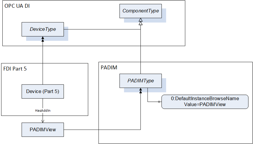
The DefaultInstanceBrowseName Property – defined in OPC 10000-3 – is used to specify the recommended BrowseName for instances of the PADIMType, see Figure 11. Its Value is defined in Table 112.
The following figure illustrates the usage of DefaultInstanceBrowseName.
Figure 11 – Example of Integration of PA-DIM with FDI Part 5 Information Model
The IVendorNamePlateType Interface items that are listed are actually inherited from ComponentType and are listed here because the ModellingRule for these instances is revised to be mandatory (they are optional in ComponentType) or restrictions are introduced here (for 2:DeviceRevision).
DeviceRevision provides the overall revision level of a hardware component or the Device. As an example, this Property can be used in ERP systems together with the ProductCode Property. SemanticVersionString (a sub-type of String defined in OPC 10000-5) shall be used when using the Semantic Versioning format. Each of <major>, <minor>, <patch> shall be able to represent a two-byte integer.
The ITagNamePlateType Interface item that is listed is actually inherited from ComponentType and is listed here because the ModellingRule for the instance is revised to be mandatory, it is only optional in ComponentType.
The DateOfLastChange shall be timestamped in the OPC UA Server.
3:<DictionaryEntryName> is an optional placeholder for an object of IrdiDictionaryEntryType that defines a predefined group of one or more classes below ABV000, e.g. Final control element or Measuring instrument. ABV000 is defined in IEC 61987 Common Data Dictionary (CDD). A Measuring instrument could be e.g. a Coriolis mass flow transmitter with the IrdiIdentifier 3:0112/2///61987#ABA763#003.
The optional SubDevices Object is used to expose sub-devices. The contained SupportedTypes Object (see OPC 10000-100) shall only reference PADIMType or ObjectTypes that are subtypes of the PADIMType, and thus all subdevices shall be instances of PADIMType or subtypes.
DeviceConditionSet is a container object for the condition parameters of the device. It has a reference to IGeneralDeviceConditionSetType to add device specific condition variables.
The components of PADIMType have additional references which are defined in Table 110.
Table 110 – PADIMType additional References
|
SourceBrowsePath |
Reference Type |
Is Forward |
TargetBrowsePath |
|
2:Manufacturer |
0:HasDictionaryEntry |
True |
|
|
2:ManufacturerUri |
0:HasDictionaryEntry |
True |
|
|
2:Model |
0:HasDictionaryEntry |
True |
|
|
2:SerialNumber |
0:HasDictionaryEntry |
True |
|
|
2:ProductCode |
0:HasDictionaryEntry |
True |
|
|
2:HardwareRevision |
0:HasDictionaryEntry |
True |
|
|
2:SoftwareRevision |
0:HasDictionaryEntry |
True |
|
|
2:DeviceRevision |
0:HasDictionaryEntry |
True |
|
|
2:RevisionCounter |
0:HasDictionaryEntry |
True |
|
|
2:ProductInstanceUri |
0:HasDictionaryEntry |
True |
|
|
2:AssetId |
0:HasDictionaryEntry |
True |
|
|
2:DeviceHealth |
0:HasDictionaryEntry |
True |
Table 111 – PADIMType additional subcomponents
|
BrowsePath |
References |
NodeClass |
BrowseName |
DataType |
TypeDefinition |
Others |
||
|
DeviceConditionSet |
0:HasInterface |
ObjectType |
IGeneralDeviceConditionSetType |
|
Defined above, see chapter 7.1.7 |
|
||
|
DeviceConditionSet |
0:HasComponent |
Object |
GeneralDeviceConditions |
|
GeneralDeviceConditionSetType |
O |
||
|
DeviceConditionSet |
0:HasComponent |
Object |
DeviceComponentConditions |
|
BaseObjectType |
O |
||
|
0:HasComponent |
Object |
<DeviceComponentIdentifier> |
|
GeneralDeviceConditionSetType |
OP |
||
The child Nodes of the PADIMType have additional Attribute values defined in Table 112. An empty field in the column “Value Attribute” means: the text field of the variable’s value attribute has the length 0.
Table 112 – PADIMType Attribute values for child Nodes
|
BrowsePath |
Value Attribute |
|
|
2:Manufacturer |
|
|
|
2:ManufacturerUri |
|
|
|
2:Model |
|
|
|
2:SerialNumber |
|
|
|
2:ProductCode |
|
|
|
2:HardwareRevision |
|
|
|
2:SoftwareRevision |
|
|
|
2:DeviceRevision |
1.0.0 |
|
|
2:RevisionCounter |
0 |
|
|
2:ProductInstanceUri |
|
|
|
2:AssetId |
|
|
|
2:DeviceHealth |
0 |
|
|
DisplayLanguage |
en |
|
|
DateOfLastChange |
1/1/1601 12:00:00 AM |
|
|
0:DefaultInstanceBrowseName |
PADIMView |
|
The ProcessAnalyserType is a subtype of the PADIMType. It is formally defined in Table 113.
Table 113 – ProcessAnalyserType definition
|
Attribute |
Value |
||||
|
BrowseName |
ProcessAnalyserType |
||||
|
IsAbstract |
False |
||||
|
References |
NodeClass |
BrowseName |
DataType |
TypeDefinition |
Other |
|
Subtype of PADIMType defined in 7.2, i.e. inheriting the InstanceDeclarations of that Node |
|||||
|
0:HasDictionaryEntry |
Object |
|
0:IrdiDictionaryEntryType |
|
|
|
Conformance Units |
|||||
|
PA-DIM ProcessAnalyserType |
|||||
3:0112/2///61987#ABP397#002 is an analytical device specific manifestation of the 3:<DictionaryEntryName> placeholder described in PADIMType.
ProcessAnalyserType is defined by IRDI as ABP397#002 which states “automation equipment that enables measurement of key quality and performance indicators in process materials and outputs a standard signal”.
The NonDispersiveInfraredGasAnalyserType is a subtype of the ProcessAnalyserType. It is formally defined in Table 114.
Table 114 – NonDispersiveInfraredGasAnalyserType definition
|
Attribute |
Value |
||||
|
BrowseName |
NonDispersiveInfraredGasAnalyserType |
||||
|
IsAbstract |
False |
||||
|
References |
NodeClass |
BrowseName |
DataType |
TypeDefinition |
Other |
|
Subtype of ProcessAnalyserType defined in 7.3, i.e. inheriting the InstanceDeclarations of that Node |
|||||
|
0:HasDictionaryEntry |
Object |
|
0:IrdiDictionaryEntryType |
|
|
|
Conformance Units |
|||||
|
PA-DIM NonDispersiveInfraredGasAnalyserType |
|||||
3:0112/2///61987#ABP425#002 is an NDIR photometer device specific manifestation of the 3:<DictionaryEntryName> placeholder described in PADIMType.
NonDispersiveInfraredGasAnalyserType is defined by IRDI as ABP425#002 which states “optical photometer that uses a light source operating in the IR spectral region that overlaps with the absorption region of the gas of interest in order to measure its concentration”.
The TocAnalyserType is a subtype of the ProcessAnalyserType. It is formally defined in Table 115.
Table 115 – TocAnalyserType definition
|
Attribute |
Value |
||||
|
BrowseName |
TocAnalyserType |
||||
|
IsAbstract |
False |
||||
|
References |
NodeClass |
BrowseName |
DataType |
TypeDefinition |
Other |
|
Subtype of ProcessAnalyserType defined in 7.3, i.e. inheriting the InstanceDeclarations of that Node |
|||||
|
0:HasComponent |
Object |
DeviceConditionSet |
|
0:BaseObjectType |
O |
|
0:HasDictionaryEntry |
Object |
|
0:IrdiDictionaryEntryType |
|
|
|
Conformance Units |
|||||
|
PA-DIM TocAnalyserType |
|||||
|
PA-DIM TocAnalyserType CarrierGasGaugePressure |
|||||
|
PA-DIM TocAnalyserType SampleWaterVolumeFlow |
|||||
|
PA-DIM TocAnalyserType ActualInjectedVolume |
|||||
3:0112/2///61987#ABP444#002 is a TOC analyser device specific manifestation of the 3:<DictionaryEntryName> placeholder described in PADIMType.
TocAnalyserType is defined by IRDI as ABP444#002 which states “sum parameter analyser for the determination of total organic carbon in water by oxidation”.
DeviceConditionSet is a container object for the condition parameters of the device. It is inherited from PADIMType and has an additional interface reference to ITocDeviceConditionSetType to add TOC analyser device specific condition variables.
The components of TocAnalyserType have additional references which are defined in Table 116.
Table 116 – TocAnalyserType additional References
|
SourceBrowsePath |
Reference Type |
Is Forward |
TargetBrowsePath |
|||
|
DeviceConditionSet |
0:HasInterface |
True |
ITocDeviceConditionSetType |
|||
|
0:HasDictionaryEntry |
True |
||||
|
0:HasDictionaryEntry |
True |
||||
|
0:HasDictionaryEntry |
True |
||||
|
0:HasDictionaryEntry |
True |
||||
|
0:HasDictionaryEntry |
True |
||||
|
0:HasDictionaryEntry |
True |
||||
|
0:HasDictionaryEntry |
True |
The components of TocAnalyserType have additional subcomponents which are defined in Table 117.
Table 117 – TocAnalyserType additional subcomponents
|
BrowsePath |
References |
NodeClass |
BrowseName |
DataType |
TypeDefinition |
Others |
|
DeviceConditionSet |
0:HasComponent |
Variable |
CarrierGasVolumeFlow |
0:Float |
0:AnalogUnitType |
O |
|
DeviceConditionSet |
0:HasComponent |
Variable |
CarrierGasGaugePressure |
0:Float |
0:AnalogUnitType |
O |
|
DeviceConditionSet |
0:HasComponent |
Variable |
ReactorTemperature |
0:Float |
0:AnalogUnitType |
O |
|
DeviceConditionSet |
0:HasComponent |
Variable |
SampleWaterVolumeFlow |
0:Float |
0:AnalogUnitType |
O |
|
DeviceConditionSet |
0:HasComponent |
Variable |
ReferenceInjectionVolume |
0:Float |
0:AnalogUnitType |
O |
|
DeviceConditionSet |
0:HasComponent |
Variable |
ActualInjectedVolume |
0:Float |
0:AnalogUnitType |
O |
|
DeviceConditionSet |
0:HasComponent |
Variable |
CoolerTemperature |
0:Float |
0:AnalogUnitType |
O |
The child Nodes of the TocAnalyserType have additional Attribute values defined in Table 118.
Table 118 – TocAnalyserType Attribute values for child Nodes
|
BrowsePath |
Value Attribute |
|||
|
0.0 |
|||
|
NamespaceUri: http://www.opcfoundation.org/UA/units/cdd/IEC62720UnitId: 705747637DisplayName: l/h Description: litre per hour |
|||
|
0.0 |
|||
|
NamespaceUri: http://www.opcfoundation.org/UA/units/cdd/IEC62720UnitId: 705749552DisplayName: mbar Description: millibar |
|||
|
0.0 |
|||
|
NamespaceUri: http://www.opcfoundation.org/UA/units/cdd/IEC62720UnitId: 705741427 DisplayName: °C Description: degree Celsius |
|||
|
0.0 |
|||
|
NamespaceUri: http://www.opcfoundation.org/UA/units/cdd/IEC62720UnitId: 705749685DisplayName: ml/min Description: millilitre per minute |
|||
|
0.0 |
|||
|
NamespaceUri: http://www.opcfoundation.org/UA/units/cdd/IEC62720 UnitId: 705749652DisplayName: ml Description: millilitre |
|||
|
0.0 |
|||
|
NamespaceUri: http://www.opcfoundation.org/UA/units/cdd/IEC62720 UnitId: 705749652DisplayName: ml Description: millilitre |
|||
|
0.0 |
|||
|
NamespaceUri: http://www.opcfoundation.org/UA/units/cdd/IEC62720UnitId: 705741427 DisplayName: °C Description: degree Celsius |
The FlameIonisationDetectorType is a subtype of the ProcessAnalyserType. It is formally defined in Table 119.
Table 119 – FlameIonisationDetectorType definition
|
Attribute |
Value |
||||
|
BrowseName |
FlameIonisationDetectorType |
||||
|
IsAbstract |
False |
||||
|
References |
NodeClass |
BrowseName |
DataType |
TypeDefinition |
Other |
|
Subtype of ProcessAnalyserType defined in 7.3, i.e. inheriting the InstanceDeclarations of that Node |
|||||
|
0:HasComponent |
Object |
DeviceConditionSet |
|
0:BaseObjectType |
O |
|
0:HasDictionaryEntry |
Object |
|
0:IrdiDictionaryEntryType |
|
|
|
Conformance Units |
|||||
|
PA-DIM FlameIonisationDetectorType |
|||||
|
PA-DIM FlameIonisationDetectorType CatalystTemperature |
|||||
|
PA-DIM FlameIonisationDetectorType FuelGasPressure |
|||||
|
PA-DIM FlameIonisationDetectorType CombustionAirPressure |
|||||
|
PA-DIM FlameIonisationDetectorType BlockTemperature |
|||||
3:0112/2///61987#ABP410#002 is an FID device specific manifestation of the 3:<DictionaryEntryName> placeholder described in PADIMType.
FlameIonisationDetectorType is defined by IRDI as ABP410#002 which states “process analyser that uses flame ionisation to measure the concentration of one or more components in a gas phase by means of the resulting ionisation current”.
DeviceConditionSet is a container object for the condition parameters of the device. It is inherited from PADIMType and has an additional interface reference to IFlameIonisationDeviceConditionSetType to add FID device specific condition variables.
The components of FlameIonisationDetectorType have additional references which are defined in Table 120.
Table 120 – FlameIonisationDetectorType additional References
|
SourceBrowsePath |
Reference Type |
Is Forward |
TargetBrowsePath |
|||
|
DeviceConditionSet |
0:HasInterface |
True |
IFlameIonisationDeviceConditionSetType |
|||
|
0:HasDictionaryEntry |
True |
||||
|
0:HasDictionaryEntry |
True |
||||
|
0:HasDictionaryEntry |
True |
||||
|
0:HasDictionaryEntry |
True |
The components of FlameIonisationDetectorType have additional subcomponents which are defined in Table 121.
Table 121 – FlameIonisationDetectorType additional subcomponents
|
BrowsePath |
References |
NodeClass |
BrowseName |
DataType |
TypeDefinition |
Others |
|
DeviceConditionSet |
0:HasComponent |
Variable |
CatalystTemperature |
0:Float |
0:AnalogUnitType |
O |
|
DeviceConditionSet |
0:HasComponent |
Variable |
FuelGasPressure |
0:Float |
0:AnalogUnitType |
O |
|
DeviceConditionSet |
0:HasComponent |
Variable |
CombustionAirPressure |
0:Float |
0:AnalogUnitType |
O |
|
DeviceConditionSet |
0:HasComponent |
Variable |
BlockTemperature |
0:Float |
0:AnalogUnitType |
O |
The child Nodes of the FlameIonisationDetectorType have additional Attribute values defined in Table 122.
Table 122 – FlameIonisationDetectorType Attribute values for child Nodes
|
BrowsePath |
Value Attribute |
|||
|
0.0 |
|||
|
NamespaceUri: http://www.opcfoundation.org/UA/units/cdd/IEC62720UnitId: 705741427 DisplayName: °CDescription: degree Celsius |
|||
|
0.0 |
|||
|
NamespaceUri: http://www.opcfoundation.org/UA/units/cdd/IEC62720UnitId: 705749552DisplayName: mbarDescription: millibar |
|||
|
0.0 |
|||
|
NamespaceUri: http://www.opcfoundation.org/UA/units/cdd/IEC62720UnitId: 705749552DisplayName: mbarDescription: millibar |
|||
|
0.0 |
|||
|
NamespaceUri: http://www.opcfoundation.org/UA/units/cdd/IEC62720UnitId: 705741427 DisplayName: °CDescription: degree Celsius |
The ParamagneticGasAnalyserType is a subtype of the ProcessAnalyserType. It is formally defined in Table 123.
Table 123 – ParamagneticGasAnalyserType definition
|
Attribute |
Value |
||||
|
BrowseName |
ParamagneticGasAnalyserType |
||||
|
IsAbstract |
False |
||||
|
References |
NodeClass |
BrowseName |
DataType |
TypeDefinition |
Other |
|
Subtype of ProcessAnalyserType defined in 7.3, i.e. inheriting the InstanceDeclarations of that Node |
|||||
|
0:HasDictionaryEntry |
Object |
|
0:IrdiDictionaryEntryType |
|
|
|
Conformance Units |
|||||
|
PA-DIM ParamagneticGasAnalyserType |
|||||
3:0112/2///61987#ABP436#002 is a paramagnetic measurement device specific manifestation of the 3:<DictionaryEntryName> placeholder described in PADIMType.
ParamagneticGasAnalyserType is defined by IRDI as ABP436#002 which states “process analyser that uses the paramagnetic susceptibility of a gas to determine its concentration in a gas mixture”.
The ThermalConductivityGasAnalyserType is a subtype of the ProcessAnalyserType. It is formally defined in Table 124.
Table 124 – ThermalConductivityGasAnalyserType definition
|
Attribute |
Value |
||||
|
BrowseName |
ThermalConductivityGasAnalyserType |
||||
|
IsAbstract |
False |
||||
|
References |
NodeClass |
BrowseName |
DataType |
TypeDefinition |
Other |
|
Subtype of ProcessAnalyserType defined in 7.3, i.e. inheriting the InstanceDeclarations of that Node |
|||||
|
0:HasDictionaryEntry |
Object |
|
0:IrdiDictionaryEntryType |
|
|
|
Conformance Units |
|||||
|
PA-DIM ThermalConductivityGasAnalyserType |
|||||
3:0112/2///61987#ABP453#002 is a thermal conductivity measurement device specific manifestation of the 3:<DictionaryEntryName> placeholder described in PADIMType.
ThermalConductivityGasAnalyserType is defined by IRDI as ABP453#002 which states “process analyser that uses the equilibrium temperature of a heated sensing element to measure the concentration of a component of a process gas”.
The TunableDiodeLaserSpectrometerType is a subtype of the ProcessAnalyserType. It is formally defined in Table 125.
Table 125 – TunableDiodeLaserSpectrometerType definition
|
Attribute |
Value |
||||
|
BrowseName |
TunableDiodeLaserSpectrometerType |
||||
|
IsAbstract |
False |
||||
|
References |
NodeClass |
BrowseName |
DataType |
TypeDefinition |
Other |
|
Subtype of ProcessAnalyserType defined in 7.3, i.e. inheriting the InstanceDeclarations of that Node |
|||||
|
0:HasDictionaryEntry |
Object |
|
0:IrdiDictionaryEntryType |
|
|
|
Conformance Units |
|||||
|
PA-DIM TunableDiodeLaserSpectrometerType |
|||||
3:0112/2///61987#ABP435#002 is a TDL device specific manifestation of the 3:<DictionaryEntryName> placeholder described in PADIMType.
TunableDiodeLaserSpectrometerType is defined by IRDI as ABP435#002 which states “optical spectrometer that uses laser absorption spectrometry at different wavelengths from UV to far IR to measure the concentration of specific components”.
The ZirconiumDioxideAnalyserType is a subtype of the ProcessAnalyserType. It is formally defined in Table 126.
Table 126 – ZirconiumDioxideAnalyserType definition
|
Attribute |
Value |
||||
|
BrowseName |
ZirconiumDioxideAnalyserType |
||||
|
IsAbstract |
False |
||||
|
References |
NodeClass |
BrowseName |
DataType |
TypeDefinition |
Other |
|
Subtype of ProcessAnalyserType defined in 7.3, i.e. inheriting the InstanceDeclarations of that Node |
|||||
|
0:HasDictionaryEntry |
Object |
|
0:IrdiDictionaryEntryType |
|
|
|
Conformance Units |
|||||
|
PA-DIM ZirconiumDioxideAnalyserType |
|||||
3:0112/2///61987#ABP409#002 is a Zirconium dioxide measurement device specific manifestation of the 3:<DictionaryEntryName> placeholder described in PADIMType.
ZirconiumDioxideAnalyserType is defined by IRDI as ABP409#002 which states “electrochemical analyser that uses a zirconium dioxide cell as sensing element to measure the concentration of oxygen in gas phase”.
The PhMeterType is a subtype of the ProcessAnalyserType. It is formally defined in Table 127.
Table 127 – PhMeterType definition
|
Attribute |
Value |
||||
|
BrowseName |
PhMeterType |
||||
|
IsAbstract |
False |
||||
|
References |
NodeClass |
BrowseName |
DataType |
TypeDefinition |
Other |
|
Subtype of ProcessAnalyserType defined in 7.3, i.e. inheriting the InstanceDeclarations of that Node |
|||||
|
0:HasDictionaryEntry |
Object |
|
0:IrdiDictionaryEntryType |
|
|
|
Conformance Units |
|||||
|
PA-DIM PhMeterType |
|||||
3:0112/2///61987#ABP440#002 is a pH meter device specific manifestation of the 3:<DictionaryEntryName> placeholder described in PADIMType.
PhMeterType is defined by IRDI as ABP440#002 which states “process analyser that measures the concentration of hydrogen ions to determine the pH value or potentiometric properties of liquids”.
The ConductivityMeterType is a subtype of the ProcessAnalyserType. It is formally defined in Table 128.
Table 128 – ConductivityMeterType definition
|
Attribute |
Value |
||||
|
BrowseName |
ConductivityMeterType |
||||
|
IsAbstract |
False |
||||
|
References |
NodeClass |
BrowseName |
DataType |
TypeDefinition |
Other |
|
Subtype of ProcessAnalyserType defined in 7.3, i.e. inheriting the InstanceDeclarations of that Node |
|||||
|
0:HasDictionaryEntry |
Object |
|
0:IrdiDictionaryEntryType |
|
|
|
Conformance Units |
|||||
|
PA-DIM ConductivityMeterType |
|||||
3:0112/2///61987#ABP405#002 is a conductivity meter device specific manifestation of the 3:<DictionaryEntryName> placeholder described in PADIMType.
ConductivityMeterType is defined by IRDI as ABP405#002 which states “process analyser that measures the conductivity to determine the concentration of electrolytes in liquids”.
The AmperometricAnalyserType is a subtype of the ProcessAnalyserType. It is formally defined in Table 129.
Table 129 – AmperometricAnalyserType definition
|
Attribute |
Value |
||||
|
BrowseName |
AmperometricAnalyserType |
||||
|
IsAbstract |
False |
||||
|
References |
NodeClass |
BrowseName |
DataType |
TypeDefinition |
Other |
|
Subtype of ProcessAnalyserType defined in 7.3, i.e. inheriting the InstanceDeclarations of that Node |
|||||
|
0:HasDictionaryEntry |
Object |
|
0:IrdiDictionaryEntryType |
|
|
|
Conformance Units |
|||||
|
PA-DIM AmperometricAnalyserType |
|||||
3:0112/2///61987#ABP407#002 is an amperometric analyser specific manifestation of the 3:<DictionaryEntryName> placeholder described in PADIMType.
AmperometricAnalyserType is defined by IRDI as ABP407#002 which states “electrochemical analyser that uses a amperometric sensing element to measure a specific component in a sample”.
The OpticalFluorescenseQuenchingSensorType is a subtype of the ProcessAnalyserType. It is formally defined in Table 130.
Table 130 – OpticalFluorescenseQuenchingSensorType definition
|
Attribute |
Value |
||||
|
BrowseName |
OpticalFluorescenseQuenchingSensorType |
||||
|
IsAbstract |
False |
||||
|
References |
NodeClass |
BrowseName |
DataType |
TypeDefinition |
Other |
|
Subtype of ProcessAnalyserType defined in 7.3, i.e. inheriting the InstanceDeclarations of that Node |
|||||
|
0:HasDictionaryEntry |
Object |
|
0:IrdiDictionaryEntryType |
|
|
|
Conformance Units |
|||||
|
PA-DIM OpticalFluorescenseQuenchingSensorType |
|||||
3:0112/2///61987#ABP423#002 is an optical Fluorescence quenching sensor specific manifestation of the 3:<DictionaryEntryName> placeholder described in PADIMType.
OpticalFluorescenseQuenchingSensorType is defined by IRDI as ABP423#002 which states “process analyser that uses the optical fluorescence quenching method to measure the concentration of a component in a gas or liquid”.
The GasChromatographType is a subtype of the ProcessAnalyserType. It is formally defined in Table 131.
Table 131 – GasChromatographType definition
|
Attribute |
Value |
||||
|
BrowseName |
GasChromatographType |
||||
|
IsAbstract |
False |
||||
|
References |
NodeClass |
BrowseName |
DataType |
TypeDefinition |
Other |
|
Subtype of ProcessAnalyserType defined in 7.3, i.e. inheriting the InstanceDeclarations of that Node |
|||||
|
0:HasComponent |
Object |
DeviceConditionSet |
|
0:BaseObjectType |
O |
|
0:HasDictionaryEntry |
Object |
|
0:IrdiDictionaryEntryType |
|
|
|
Conformance Units |
|||||
|
PA-DIM GasChromatographSignalType |
|||||
|
PA-DIM GasChromatographSignalType Peak |
|||||
|
PA-DIM GasChromatographSignalType RetentionTime |
|||||
|
PA-DIM GasChromatographSignalType InjectionTime |
|||||
|
PA-DIM GasChromatographSignalType ComponentName |
|||||
3:0112/2///61987#ABP400#002 is a Gaschromatograph device specific manifestation of the 3:<DictionaryEntryName> placeholder described in PADIMType.
GasChromatographType is defined by IRDI as ABP400#002 which states “chromatograph that takes a gaseous sample or liquid samples that can be vaporized and separates the components in a gaseous phase”.
The components of GasChromatographType have additional references which are defined in Table 132.
Table 132 – GasChromatographType additional References
|
SourceBrowsePath |
Reference Type |
Is Forward |
TargetBrowsePath |
|||
|
DeviceConditionSet |
0:HasInterface |
True |
IGasChromatographDeviceConditionSetType |
|||
|
0:HasDictionaryEntry |
True |
||||
|
0:HasDictionaryEntry |
True |
||||
|
0:HasDictionaryEntry |
True |
The components of GasChromatographType have additional subcomponents which are defined in Table 133.
Table 133 – GasChromatographType additional subcomponents
|
BrowsePath |
References |
NodeClass |
BrowseName |
DataType |
TypeDefinition |
Others |
|
DeviceConditionSet |
0:HasProperty |
Variable |
ValveName |
0:LocalizedText[] |
0:PropertyType |
O |
|
DeviceConditionSet |
0:HasProperty |
Variable |
ValveSwitchingCyclesCounter |
0:UInt32[] |
0:PropertyType |
O |
|
DeviceConditionSet |
0:HasComponent |
Variable |
TotalAreaMeasuredPeaks |
0:Float |
0:AnalogUnitType |
O |
|
DeviceConditionSet |
0:HasComponent |
Variable |
BaselineNoise |
0:Float |
0:AnalogUnitType |
O |
The child Nodes of the GasChromatographType have additional Attribute values defined in Table 134.
Table 134 – GasChromatographType Attribute values for child Nodes
|
BrowsePath |
Value Attribute |
|||
|
|
|||
|
0 |
|||
|
0.0 |
|||
|
NamespaceUri: http://www.opcfoundation.org/UA/units/cdd/IEC62720 UnitId: 705741328 DisplayName: % Description: percent |
|||
|
0.0 |
|||
|
NamespaceUri: http://www.opcfoundation.org/UA/units/cdd/IEC62720UnitId: 705749524 DisplayName: mVDescription: millivolt |
The InfraredSensorType is a subtype of the ProcessAnalyserType. It is formally defined in Table 135.
Table 135 – InfraredSensorType definition
|
Attribute |
Value |
||||
|
BrowseName |
InfraredSensorType |
||||
|
IsAbstract |
False |
||||
|
References |
NodeClass |
BrowseName |
DataType |
TypeDefinition |
Other |
|
Subtype of ProcessAnalyserType defined in 7.3, i.e. inheriting the InstanceDeclarations of that Node |
|||||
|
0:HasComponent |
Object |
DeviceConditionSet |
|
0:BaseObjectType |
O |
|
0:HasDictionaryEntry |
Object |
|
0:IrdiDictionaryEntryType |
|
|
|
Conformance Units |
|||||
|
PA-DIM InfraredSensorType |
|||||
|
|
|||||
|
|
|||||
|
|
|||||
3:0112/2///61987#ABP413#002 is a Infrared sensor specific manifestation of the 3:<DictionaryEntryName> placeholder described in PADIMType.
InfraredSensorType is defined by IRDI as ABP413#002 which states “gas detector that uses a broadband IR light source and optical filter to select a narrow-band spectral region that overlaps with the absorption region of the gas of interest”.
The AmperometricGasDetectorType is a subtype of the ProcessAnalyserType. It is formally defined in Table 136.
Table 136 – AmperometricGasDetectorType definition
|
Attribute |
Value |
||||
|
BrowseName |
AmperometricGasDetectorType |
||||
|
IsAbstract |
False |
||||
|
References |
NodeClass |
BrowseName |
DataType |
TypeDefinition |
Other |
|
Subtype of ProcessAnalyserType defined in 7.3, i.e. inheriting the InstanceDeclarations of that Node |
|||||
|
0:HasComponent |
Object |
DeviceConditionSet |
|
0:BaseObjectType |
O |
|
0:HasDictionaryEntry |
Object |
|
0:IrdiDictionaryEntryType |
|
|
|
Conformance Units |
|||||
|
PA-DIM AmperometricGasDetectorType |
|||||
|
|
|||||
|
|
|||||
|
|
|||||
ABP415#002 is an amperometric gas detector specific manifestation of the 3:<DictionaryEntryName> placeholder described in PADIMType.
AmperometricGasDetectorType is defined by IRDI as ABP415#002 which states “gas detector that uses a amperometric sensing element to measure oxygen or other gases”.
The CatalyticBeadSensorType is a subtype of the ProcessAnalyserType. It is formally defined in Table 137.
Table 137 – CatalyticBeadSensorType definition
|
Attribute |
Value |
||||
|
BrowseName |
CatalyticBeadSensorType |
||||
|
IsAbstract |
False |
||||
|
References |
NodeClass |
BrowseName |
DataType |
TypeDefinition |
Other |
|
Subtype of ProcessAnalyserType defined in 7.3, i.e. inheriting the InstanceDeclarations of that Node |
|||||
|
0:HasComponent |
Object |
DeviceConditionSet |
|
0:BaseObjectType |
O |
|
0:HasDictionaryEntry |
Object |
|
0:IrdiDictionaryEntryType |
|
|
|
Conformance Units |
|||||
|
PA-DIM CatalyticBeadSensorType |
|||||
|
|
|||||
|
|
|||||
|
|
|||||
3:0112/2///61987#ABP412#002 is a catalytic bead sensor specific manifestation of the 3:<DictionaryEntryName> placeholder described in PADIMType.
CatalyticBeadSensorType is defined by IRDI as ABP412#002 which states “gas detector that uses catalytic bead principle for the detection of flammable gas in lower explosion level”.
The FtnirOrFtirSpectrometerType is a subtype of the ProcessAnalyserType. It is formally defined in Table 138.
Table 138 – FtnirOrFtirSpectrometerType definition
|
Attribute |
Value |
||||
|
BrowseName |
FtnirOrFtirSpectrometerType |
||||
|
IsAbstract |
False |
||||
|
References |
NodeClass |
BrowseName |
DataType |
TypeDefinition |
Other |
|
Subtype of ProcessAnalyserType defined in 7.3, i.e. inheriting the InstanceDeclarations of that Node |
|||||
|
0:HasComponent |
Object |
DeviceConditionSet |
|
0:BaseObjectType |
O |
|
0:HasDictionaryEntry |
Object |
|
0:IrdiDictionaryEntryType |
|
|
|
Conformance Units |
|||||
|
PA-DIM FtnirOrFtirSpectrometerType |
|||||
|
PA-DIM FtnirOrFtirSpectrometerType Watchdog |
|||||
|
PA-DIM FtnirOrFtirSpectrometerType RemainingDataStorageCapacity |
|||||
3:0112/2///61987#ABP432#002 is a fourier transform near infrared or fourier transform infrared specific manifestation of the 3:<DictionaryEntryName> placeholder described in PADIMType.
FtnirOrFtirSpectrometerType is defined by IRDI as ABP432#002 which states “optical spectrometer operating in the near infrared or infrared spectral region that uses an interferometer and Fourier Transformation to measure the concentration of specific components”.
The DiodeArraySpectrometerType is a subtype of the ProcessAnalyserType. It is formally defined in Table 139.
Table 139 – DiodeArraySpectrometerType definition
|
Attribute |
Value |
||||
|
BrowseName |
DiodeArraySpectrometerType |
||||
|
IsAbstract |
False |
||||
|
References |
NodeClass |
BrowseName |
DataType |
TypeDefinition |
Other |
|
Subtype of ProcessAnalyserType defined in 7.3, i.e. inheriting the InstanceDeclarations of that Node |
|||||
|
0:HasComponent |
Object |
DeviceConditionSet |
|
0:BaseObjectType |
O |
|
0:HasDictionaryEntry |
Object |
|
0:IrdiDictionaryEntryType |
|
|
|
Conformance Units |
|||||
|
PA-DIM DiodeArraySpectrometerType |
|||||
|
|
|||||
|
|
|||||
|
|
|||||
3:0112/2///61987#ABP433#002 is a diode array spectrometer specific manifestation of the 3:<DictionaryEntryName> placeholder described in PADIMType.
DiodeArraySpectrometerType is defined by IRDI as #ABP433#002 which states “optical spectrometer operating in the UV and/or visible and/or IR spectral region that uses a broadband light source, dispersive elements and a diode array detector to measure the concentration of specific components”.
The RamanSpectrometerType is a subtype of the ProcessAnalyserType. It is formally defined in Table 140.
Table 140 – RamanSpectrometerType definition
|
Attribute |
Value |
||||
|
BrowseName |
RamanSpectrometerType |
||||
|
IsAbstract |
False |
||||
|
References |
NodeClass |
BrowseName |
DataType |
TypeDefinition |
Other |
|
Subtype of ProcessAnalyserType defined in 7.3, i.e. inheriting the InstanceDeclarations of that Node |
|||||
|
0:HasComponent |
Object |
DeviceConditionSet |
|
0:BaseObjectType |
O |
|
0:HasDictionaryEntry |
Object |
|
0:IrdiDictionaryEntryType |
|
|
|
Conformance Units |
|||||
|
PA-DIM RamanSpectrometerType |
|||||
|
|
|||||
|
|
|||||
|
|
|||||
0112/2///61987#ABP434#002 is a Raman spectrometer specific manifestation of the 3:<DictionaryEntryName> placeholder described in PADIMType.
RamanSpectrometerType is defined by IRDI as ABP434#002 which states “optical spectrometer operating in the UV, visible and IR spectral region that uses Raman scattering to measure the concentration of specific components”.
The SignalSetType provides the signals of the device and is formally defined in Table 141.
Table 141 – SignalSetType definition
|
Attribute |
Value |
||||
|
BrowseName |
SignalSetType |
||||
|
IsAbstract |
False |
||||
|
References |
NodeClass |
BrowseName |
DataType |
TypeDefinition |
Other |
|
Subtype of 0:BaseObjectType defined in OPC 10000-5, i.e. inheriting the InstanceDeclarations of that Node |
|||||
|
0:HasComponent |
Object |
<SignalIdentifier> |
|
SignalType |
OP |
|
Conformance Units |
|||||
|
PA-DIM SignalSet |
|||||
The child Nodes of the SignalSetType have additional Attribute values defined in Table 142. An empty field in the column “Value Attribute” means: the text field of the variable’s value attribute has the length 0.
Table 142 – SignalSetType Attribute values for child Nodes
|
BrowsePath |
Value Attribute |
||
|
|
The CalibrationPointSetType provides the calibration points of a sensor resp. signal and is formally defined in Table 143.
Table 143 – CalibrationPointSetType definition
|
Attribute |
Value |
||||
|
BrowseName |
CalibrationPointSetType |
||||
|
IsAbstract |
False |
||||
|
References |
NodeClass |
BrowseName |
DataType |
TypeDefinition |
Other |
|
Subtype of 0:BaseObjectType defined in OPC 10000-5, i.e. inheriting the InstanceDeclarations of that Node |
|||||
|
0:HasComponent |
Object |
<CalibrationPointIdentifier> |
|
CalibrationPointType |
OP |
|
Conformance Units |
|||||
|
PA-DIM ICalibration CalibrationPointSet |
|||||
The GeneralDeviceConditionSetType provides the general condition variables of the device ore one of its components and is formally defined in Table 144.
Table 144 – GeneralDeviceConditionSetType definition
|
Attribute |
Value |
||||
|
BrowseName |
GeneralDeviceConditionSetType |
||||
|
IsAbstract |
False |
||||
|
References |
NodeClass |
BrowseName |
DataType |
TypeDefinition |
Other |
|
Subtype of 0:BaseObjectType defined in OPC 10000-5, i.e. inheriting the InstanceDeclarations of that Node |
|||||
|
0:HasComponent |
Variable |
InternalTemperature |
0:Float{Any} |
0:AnalogUnitType |
O |
|
0:HasProperty |
Variable |
ResidualLife |
0:Float |
0:PropertyType |
O |
|
0:HasInterface |
ObjectType |
2:IOperationCounterType |
|
Defined in OPC 10000-100 |
|
|
0:HasProperty |
Variable |
2:PowerOnDuration |
0:Duration |
0:PropertyType |
O |
|
0:HasProperty |
Variable |
2:OperationDuration |
0:Duration |
0:PropertyType |
O |
|
0:HasProperty |
Variable |
2:OperationCycleCounter |
0:UInteger |
0:PropertyType |
O |
|
Conformance Units |
|||||
|
PA-DIM GeneralDeviceConditionSetType InternalTemperature |
|||||
|
PA-DIM GeneralDeviceConditionSetType ResidualLife |
|||||
|
PA-DIM GeneralDeviceConditionSetType PowerOnDuration |
|||||
|
PA-DIM GeneralDeviceConditionSetType OperationDuration |
|||||
|
PA-DIM GeneralDeviceConditionSetType OperationCycleCounter |
|||||
InternalTemperature is defined by IRDI as ABP591#001 which states “temperature measured at a relevant internal position defined by the manufacturer”.
ResidualLife is defined by IRDI as ABP595#001 which states “degradation of a device or device component expressed as a value between 1 (good) and 0 (bad)”.
PowerOnDuration is defined by IRDI as ABP550#001 which states “summed duration of time intervals for which an item was supplied with energy”.
OperationDuration is defined by IRDI as ABN639#001 which states “summed duration of time intervals for which an item was in an active (non idle) operating state”.
OperationCycleCounter is defined by IRDI as ABP545#001 which states “result of the addition of switching events from idle to active state of an object”.
The components of GeneralDeviceConditionSetType have additional references which are defined in Table 145.
Table 145 – GeneralDeviceConditionSetType additional References
|
SourceBrowsePath |
Reference Type |
Is Forward |
TargetBrowsePath |
||
|
InternalTemperature |
0:HasDictionaryEntry |
True |
|||
|
0:HasDictionaryEntry |
True |
|||
|
ResidualLife |
0:HasDictionaryEntry |
True |
|||
|
2:PowerOnDuration |
0:HasDictionaryEntry |
True |
|||
|
2:OperationDuration |
0:HasDictionaryEntry |
True |
|||
|
2:OperationCycleCounter |
0:HasDictionaryEntry |
True |
The child Nodes of the GeneralDeviceConditionSetType have additional Attribute values defined in Table 146.
Table 146 – GeneralDeviceConditionSetType Attribute values for child Nodes
|
BrowsePath |
Value Attribute |
||
|
InternalTemperature |
0.0 |
||
|
NamespaceUri: http://www.opcfoundation.org/UA/units/cdd/IEC62720UnitId: 705741427 DisplayName: °CDescription: degree Celsius |
||
|
ResidualLife |
1.0 |
||
|
2:PowerOnDuration |
0.0 |
||
|
2:OperationDuration |
0.0 |
The SignalType provides ObjectType to add analog and discrete signals and is formally defined in Table 147. In order to have a common approach, PA-DIM will always use Objects, even if no Method is needed for some types.
Table 147 – SignalType definition
|
Attribute |
Value |
||||
|
BrowseName |
SignalType |
||||
|
IsAbstract |
False |
||||
|
References |
NodeClass |
BrowseName |
DataType |
TypeDefinition |
Other |
|
Subtype of 0:BaseObjectType defined in OPC 10000-5, i.e. inheriting the InstanceDeclarations of that Node |
|||||
|
0:HasProperty |
Variable |
SignalTag |
0:String |
0:PropertyType |
M |
|
Conformance Units |
|||||
|
PA-DIM SignalSet |
|||||
SignalTag is defined by IRDI as ABB271#009 which states “alphanumeric character sequence uniquely identifying a measuring or control point”
The components of SignalType have additional references which are defined in Table 148.
Table 148 – SignalType additional References
|
SourceBrowsePath |
Reference Type |
Is Forward |
TargetBrowsePath |
|
SignalTag |
0:HasDictionaryEntry |
True |
The child Nodes of the SignalType have additional Attribute values defined in Table 149. An empty field in the column “Value Attribute” means: the text field of the variable’s value attribute has the length 0.
Table 149 – SignalType Attribute values for child Nodes
|
BrowsePath |
Value Attribute |
|
SignalTag |
|
The AnalogSignalType provides ObjectType to add variables and ZeroPointAdjustment Method. It is formally defined in Table 150.
Table 150 – AnalogSignalType definition
|
Attribute |
Value |
||||
|
BrowseName |
AnalogSignalType |
||||
|
IsAbstract |
False |
||||
|
References |
NodeClass |
BrowseName |
DataType |
TypeDefinition |
Other |
|
Subtype of SignalType defined in 7.23, i.e. inheriting the InstanceDeclarations of that Node |
|||||
|
0:HasComponent |
Method |
ZeroPointAdjustment |
Defined in 9.2 |
O |
|
|
0:HasComponent |
Variable |
AnalogSignal |
0:Number{Any} |
AnalogSignalVariableType |
M |
|
0:HasComponent |
Object |
<SignalCalibrationIdentifier> |
|
0:BaseObjectType |
OP |
|
0:HasComponent |
Object |
SignalConditionSet |
|
0:BaseObjectType |
O |
|
Conformance Units |
|||||
|
PA-DIM Analog Signal |
|||||
|
PA-DIM ZeroPointAdjustment method |
|||||
|
PA-DIM ICalibration |
|||||
|
PA-DIM ICalibration CalibrationTimestamp |
|||||
|
PA-DIM ICalibration TypeOfCalibration |
|||||
|
PA-DIM ICalibration CalibrationPointSet |
|||||
|
PA-DIM Signal Condition Set |
|||||
ZeroPointAdjustment: ABN614#002 defines property that initiates when set the TRUE (ON) state a procedure, which maybe automatic, to define or set the value zero of the output. Remark: properties can be variables or methods according to IEC 61987 CDD.
AnalogSignal provides the measured or readback process value. The unit of this value is provided by the EngineeringUnits property.
<SignalCalibrationIdentifier> is a container object for the calibration parameters of the signal. It has an interface reference to ICalibrationType in order to add general calibration variables. Since it is a placeholder, an instance of AnalogSignalType can have several calibration objects.
SignalConditionSet is a container object for the condition parameters of the signal.
The components of AnalogSignalType have additional references which are defined in Table 151.
Table 151 – AnalogSignalType additional References
|
SourceBrowsePath |
Reference Type |
Is Forward |
TargetBrowsePath |
||
|
0:HasDictionaryEntry |
True |
|||
|
<SignalCalibrationIdentifier> |
0:HasInterface |
True |
ICalibrationType |
||
|
ZeroPointAdjustment |
0:HasDictionaryEntry |
True |
The components of AnalogSignalType have additional subcomponents which are defined in Table 152.
Table 152 – AnalogSignalType additional subcomponents
|
BrowsePath |
References |
NodeClass |
BrowseName |
DataType |
TypeDefinition |
Others |
|
<SignalCalibrationIdentifier> |
0:HasProperty |
Variable |
CalibrationTimestamp |
0:DateTime |
0:PropertyType |
O |
|
<SignalCalibrationIdentifier> |
0:HasComponent |
Variable |
TypeOfCalibration |
0:UInt32 |
0:MultiStateDictionaryEntryDiscreteType |
O |
|
<SignalCalibrationIdentifier> |
0:HasComponent |
Object |
CalibrationPointSet |
|
CalibrationPointSetType |
O |
The child Nodes of the AnalogSignalType have additional Attribute values defined in Table 153.
Table 153 – AnalogSignalType Attribute values for child Nodes
|
BrowsePath |
Value Attribute |
|||
|
1/1/1601 12:00:00 AM |
|||
|
0 |
|||
|
ns=3;s=0112/2///61987#ABP732#001 |
|||
|
adjustment |
The AnalyticalSignalType provides ObjectType to add analytical measurement specific variables. It is formally defined in Table 154.
Table 154 – AnalyticalSignalType definition
|
Attribute |
Value |
||||
|
BrowseName |
AnalyticalSignalType |
||||
|
IsAbstract |
False |
||||
|
References |
NodeClass |
BrowseName |
DataType |
TypeDefinition |
Other |
|
Subtype of AnalogSignalType defined in 7.26, i.e. inheriting the InstanceDeclarations of that Node |
|||||
|
0:HasComponent |
Variable |
AnalogSignal |
0:Float |
PatMeasurementVariableType |
M |
|
Conformance Units |
|||||
|
PA-DIM AnalyticalSignalType |
|||||
AnalogSignal is inherited from AnalogSignalType. In AnalyticalSignalType its TypeDefinition is specialized to PatMeasurementVariableType.
The components of AnalyticalSignalType have additional references which are defined in Table 155.
Table 155 – AnalyticalSignalType additional References
|
SourceBrowsePath |
Reference Type |
Is Forward |
TargetBrowsePath |
||
|
0:HasDictionaryEntry |
True |
The NonDispersiveInfraredSignalType provides ObjectType to add NDIR measurement specific variables. It is formally defined in Table 156.
Table 156 – NonDispersiveInfraredSignalType definition
|
Attribute |
Value |
||||
|
BrowseName |
NonDispersiveInfraredSignalType |
||||
|
IsAbstract |
False |
||||
|
References |
NodeClass |
BrowseName |
DataType |
TypeDefinition |
Other |
|
Subtype of AnalyticalSignalType defined in 7.27, i.e. inheriting the InstanceDeclarations of that Node |
|||||
|
0:HasComponent |
Object |
SignalConditionSet |
|
0:BaseObjectType |
O |
|
Conformance Units |
|||||
|
PA-DIM NonDispersiveInfraredSignalType |
|||||
|
PA-DIM NonDispersiveInfraredSignalType ChopperFrequencyDeviation |
|||||
|
PA-DIM NonDispersiveInfraredSignalType AbsoluteSampleGasPressure |
|||||
SignalConditionSet is a container object for the condition parameters of the signal. It is inherited from AnalogSignalType and has an additional interface reference to INonDispersiveInfraredSignalConditionSetType to add NDIR signal specific condition variables. The components of NonDispersiveInfraredSignalType have additional references which are defined in Table 157.
Table 157 – NonDispersiveInfraredSignalType additional References
|
SourceBrowsePath |
Reference Type |
Is Forward |
TargetBrowsePath |
|||
|
SignalConditionSet |
0:HasInterface |
True |
INonDispersiveInfraredSignalConditionSetType |
|||
|
0:HasDictionaryEntry |
True |
||||
|
0:HasDictionaryEntry |
True |
||||
|
0:HasDictionaryEntry |
True |
The components of NonDispersiveInfraredSignalType have additional subcomponents which are defined in Table 158.
Table 158 – NonDispersiveInfraredSignalType additional subcomponents
|
BrowsePath |
References |
NodeClass |
BrowseName |
DataType |
TypeDefinition |
Others |
|
SignalConditionSet |
0:HasComponent |
Variable |
ChopperFrequencyDeviation |
0:Float |
0:BaseAnalogType |
O |
|
SignalConditionSet |
0:HasComponent |
Variable |
AbsoluteSampleGasPressure |
0:Float |
0:AnalogUnitType |
O |
|
SignalConditionSet |
0:HasComponent |
Variable |
SampleCellTemperature |
0:Float |
0:AnalogUnitType |
O |
|
SignalConditionSet |
0:HasProperty |
Variable |
SourceResidualLife |
0:Float |
0:PropertyType |
O |
The child Nodes of the NonDispersiveInfraredSignalType have additional Attribute values defined in Table 159.
Table 159 – NonDispersiveInfraredSignalType Attribute values for child Nodes
|
BrowsePath |
Value Attribute |
|||
|
0.0 |
|||
|
NamespaceUri: http://www.opcfoundation.org/UA/units/cdd/IEC62720 UnitId: 705741328 DisplayName: % Description: percent |
|||
|
0.0 |
|||
|
NamespaceUri: http://www.opcfoundation.org/UA/units/cdd/IEC62720UnitId: 705749552DisplayName: mbarDescription: millibar |
|||
|
0.0 |
|||
|
NamespaceUri: http://www.opcfoundation.org/UA/units/cdd/IEC62720UnitId: 705741427 DisplayName: °CDescription: degree Celsius |
|||
|
1.0 |
The TocSignalType provides ObjectType to add TOC measurement specific variables. It is formally defined in Table 160.
Table 160 – TocSignalType definition
|
Attribute |
Value |
||||
|
BrowseName |
TocSignalType |
||||
|
IsAbstract |
False |
||||
|
References |
NodeClass |
BrowseName |
DataType |
TypeDefinition |
Other |
|
Subtype of AnalyticalSignalType defined in 7.27, i.e. inheriting the InstanceDeclarations of that Node |
|||||
|
0:HasComponent |
Object |
SignalConditionSet |
|
0:BaseObjectType |
O |
|
Conformance Units |
|||||
|
PA-DIM TocSignalType |
|||||
|
PA-DIM TocSignalType ChopperFrequencyDeviation |
|||||
|
PA-DIM TocSignalType RelativeReagentLevel |
|||||
|
PA-DIM TocSignalType AbsoluteSampleGasPressure |
|||||
|
PA-DIM TocSignalType SampleGasVolumeFlow |
|||||
SignalConditionSet is a container object for the condition parameters of the signal. It is inherited from AnalogSignalType and has an additional interface reference to ITocSignalConditionSetType to add TOC signal specific condition variables.
The components of TocSignalType have additional references which are defined in Table 161.
Table 161 – TocSignalType additional References
|
SourceBrowsePath |
Reference Type |
Is Forward |
TargetBrowsePath |
|||
|
SignalConditionSet |
0:HasInterface |
True |
ITocSignalConditionSetType |
|||
|
0:HasDictionaryEntry |
True |
||||
|
0:HasDictionaryEntry |
True |
||||
|
0:HasDictionaryEntry |
True |
||||
|
0:HasDictionaryEntry |
True |
||||
|
0:HasDictionaryEntry |
True |
||||
|
0:HasDictionaryEntry |
True |
The components of TocSignalType have additional subcomponents which are defined in Table 162.
Table 162 – TocSignalType additional subcomponents
|
BrowsePath |
References |
NodeClass |
BrowseName |
DataType |
TypeDefinition |
Others |
|
SignalConditionSet |
0:HasComponent |
Variable |
ChopperFrequencyDeviation |
0:Float |
0:BaseAnalogType |
O |
|
SignalConditionSet |
0:HasComponent |
Variable |
RelativeReagentLevel |
0:Float{Any} |
0:AnalogUnitType |
O |
|
SignalConditionSet |
0:HasComponent |
Variable |
SampleCellTemperature |
0:Float |
0:AnalogUnitType |
O |
|
SignalConditionSet |
0:HasComponent |
Variable |
DetectorZeroSignal |
0:Float |
0:AnalogUnitType |
O |
|
SignalConditionSet |
0:HasProperty |
Variable |
SourceResidualLife |
0:Float |
0:PropertyType |
O |
|
SignalConditionSet |
0:HasComponent |
Variable |
AbsoluteSampleGasPressure |
0:Float |
0:AnalogUnitType |
O |
|
SignalConditionSet |
0:HasComponent |
Variable |
SampleGasVolumeFlow |
0:Float |
0:AnalogUnitType |
O |
The child Nodes of the TocSignalType have additional Attribute values defined in Table 163.
Table 163 – TocSignalType Attribute values for child Nodes
|
BrowsePath |
Value Attribute |
|||
|
0.0 |
|||
|
NamespaceUri: http://www.opcfoundation.org/UA/units/cdd/IEC62720 UnitId: 705741328 DisplayName: % Description: percent |
|||
|
0.0 |
|||
|
NamespaceUri: http://www.opcfoundation.org/UA/units/cdd/IEC62720 UnitId: 705741328 DisplayName: % Description: percent |
|||
|
0.0 |
|||
|
NamespaceUri: http://www.opcfoundation.org/UA/units/cdd/IEC62720UnitId: 705741427 DisplayName: °CDescription: degree Celsius |
|||
|
0.0 |
|||
|
NamespaceUri: http://www.opcfoundation.org/UA/units/cdd/IEC62720 UnitId: 705848917 DisplayName: ppm Description: parts per million |
|||
|
1.0 |
|||
|
0.0 |
|||
|
NamespaceUri: http://www.opcfoundation.org/UA/units/cdd/IEC62720UnitId: 705749552DisplayName: mbarDescription: millibar |
|||
|
0.0 |
|||
|
NamespaceUri: http://www.opcfoundation.org/UA/units/cdd/IEC62720UnitId: 705747637DisplayName: l/hDescription: litre per hour |
The ParamagneticSignalType provides ObjectType to add paramagnetic measurement specific variables. It is formally defined in Table 164.
Table 164 – ParamagneticSignalType definition
|
Attribute |
Value |
||||
|
BrowseName |
ParamagneticSignalType |
||||
|
IsAbstract |
False |
||||
|
References |
NodeClass |
BrowseName |
DataType |
TypeDefinition |
Other |
|
Subtype of AnalyticalSignalType defined in 7.27, i.e. inheriting the InstanceDeclarations of that Node |
|||||
|
0:HasComponent |
Object |
SignalConditionSet |
|
0:BaseObjectType |
O |
|
Conformance Units |
|||||
|
PA-DIM ParamagneticSignalType |
|||||
SignalConditionSet is a container object for the condition parameters of the signal. It is inherited from AnalogSignalType and has an additional interface reference to IParamagneticSignalConditionSetType to add paramagnetic signal specific condition variables.
The components of ParamagneticSignalType have additional references which are defined in Table 165.
Table 165 – ParamagneticSignalType additional References
|
SourceBrowsePath |
Reference Type |
Is Forward |
TargetBrowsePath |
|||
|
SignalConditionSet |
0:HasInterface |
True |
IParamagneticSignalConditionSetType |
|||
|
0:HasDictionaryEntry |
True |
||||
|
0:HasDictionaryEntry |
True |
The components of ParamagneticSignalType have additional subcomponents which are defined in Table 166.
Table 166 – ParamagneticSignalType Additional Subcomponents
|
BrowsePath |
References |
NodeClass |
BrowseName |
DataType |
TypeDefinition |
Others |
|
SignalConditionSet |
0:HasComponent |
Variable |
SampleTemperature |
0:Float |
0:AnalogUnitType |
O |
|
SignalConditionSet |
0:HasComponent |
Variable |
SensingElementTemperature |
0:Float |
0:AnalogUnitType |
O |
The child Nodes of the ParamagneticSignalType have additional Attribute values defined in Table 167.
Table 167 – ParamagneticSignalType Attribute values for child Nodes
|
BrowsePath |
Value Attribute |
|||
|
0.0 |
|||
|
NamespaceUri: http://www.opcfoundation.org/UA/units/cdd/IEC62720UnitId: 705741427 DisplayName: °CDescription: degree Celsius |
|||
|
0.0 |
|||
|
NamespaceUri: http://www.opcfoundation.org/UA/units/cdd/IEC62720 UnitId: 705741427 DisplayName: °C Description: degree Celsius |
The ThermalConductivitySignalType provides ObjectType to add thermal conductivity measurement specific variables. It is formally defined in Table 168.
Table 168 – ThermalConductivitySignalType definition
|
Attribute |
Value |
||||
|
BrowseName |
ThermalConductivitySignalType |
||||
|
IsAbstract |
False |
||||
|
References |
NodeClass |
BrowseName |
DataType |
TypeDefinition |
Other |
|
Subtype of AnalyticalSignalType defined in 7.27, i.e. inheriting the InstanceDeclarations of that Node |
|||||
|
0:HasComponent |
Object |
SignalConditionSet |
|
0:BaseObjectType |
O |
|
Conformance Units |
|||||
|
PA-DIM ThermalConductivitySignalType |
|||||
SignalConditionSet is a container object for the condition parameters of the signal. It is inherited from AnalogSignalType and has an additional interface reference to IThermalConductivitySignalConditionSetType to add thermal conductivity signal specific condition variables.
The components of ThermalConductivitySignalType have additional references which are defined in Table 169.
Table 169 – ThermalConductivitySignalType additional References
|
SourceBrowsePath |
Reference Type |
Is Forward |
TargetBrowsePath |
|||
|
SignalConditionSet |
0:HasInterface |
True |
IThermalConductivitySignalConditionSetType |
|||
|
0:HasDictionaryEntry |
True |
The components of ThermalConductivitySignalType have additional subcomponents which are defined in Table 170.
Table 170 – ThermalConductivitySignalType additional subcomponents
|
BrowsePath |
References |
NodeClass |
BrowseName |
DataType |
TypeDefinition |
Others |
|
SignalConditionSet |
0:HasComponent |
Variable |
SampleTemperature |
0:Float |
0:AnalogUnitType |
O |
The child Nodes of the ThermalConductivitySignalType have additional Attribute values defined in Table 171.
Table 171 – ThermalConductivitySignalType Attribute values for child Nodes
|
BrowsePath |
Value Attribute |
|||
|
0.0 |
|||
|
NamespaceUri: http://www.opcfoundation.org/UA/units/cdd/IEC62720UnitId: 705741427 DisplayName: °CDescription: degree Celsius |
The TunableDiodeLaserSignalType provides ObjectType to add TDL measurement specific variables. It is formally defined in Table 172.
Table 172 – TunableDiodeLaserSignalType definition
|
Attribute |
Value |
||||
|
BrowseName |
TunableDiodeLaserSignalType |
||||
|
IsAbstract |
False |
||||
|
References |
NodeClass |
BrowseName |
DataType |
TypeDefinition |
Other |
|
Subtype of AnalyticalSignalType defined in 7.27, i.e. inheriting the InstanceDeclarations of that Node |
|||||
|
0:HasComponent |
Object |
SignalConditionSet |
|
0:BaseObjectType |
O |
|
Conformance Units |
|||||
|
PA-DIM TunableDiodeLaserSignalType |
|||||
|
PA-DIM TunableDiodeLaserSignalType SignalFitQuality |
|||||
|
PA-DIM TunableDiodeLaserSignalType SignalNoiseRatio |
|||||
|
PA-DIM TunableDiodeLaserSignalType TransmissionRatio |
|||||
|
PA-DIM TunableDiodeLaserSignalType LaserTemperature |
|||||
|
PA-DIM TunableDiodeLaserSignalType AbsoluteSampleGasPressure |
|||||
SignalConditionSet is a container object for the condition parameters of the signal. It is inherited from AnalogSignalType and has an additional interface reference to ITunableDiodeLaserSignalConditionSetType to add TDL signal specific condition variables.
The components of TunableDiodeLaserSignalType have additional references which are defined in Table 173.
Table 173 – TunableDiodeLaserSignalType additional References
|
SourceBrowsePath |
Reference Type |
Is Forward |
TargetBrowsePath |
|||
|
SignalConditionSet |
0:HasInterface |
True |
ITunableDiodeLaserSignalConditionSetType |
|||
|
0:HasDictionaryEntry |
True |
||||
|
0:HasDictionaryEntry |
True |
||||
|
0:HasDictionaryEntry |
True |
The components of TunableDiodeLaserSignalType have additional subcomponents which are defined in Table 174.
Table 174 – TunableDiodeLaserSignalType additional subcomponents
|
BrowsePath |
References |
NodeClass |
BrowseName |
DataType |
TypeDefinition |
Others |
|
|
SignalConditionSet |
0:HasComponent |
Variable |
AbsoluteSampleGasPressure |
0:Float |
0:AnalogUnitType |
O |
|
|
SignalConditionSet |
0:HasComponent |
Variable |
SampleTemperature |
0:Float |
0:AnalogUnitType |
O |
|
|
SignalConditionSet |
0:HasComponent |
Variable |
TransmissionRatio |
0:Float |
0:DataItemType |
O |
|
|
SignalConditionSet |
0:HasComponent |
Variable |
SignalNoiseRatio |
0:Float |
0:DataItemType |
O |
|
|
SignalConditionSet |
0:HasComponent |
Variable |
LaserTemperature |
0:Float |
0:AnalogUnitType |
O |
|
|
SignalConditionSet |
0:HasComponent |
Variable |
SignalFitQuality |
0:Float |
0:DataItemType |
O |
|
The child Nodes of the TunableDiodeLaserSignalType have additional Attribute values defined in Table 175.
Table 175 – TunableDiodeLaserSignalType Attribute values for child Nodes
|
BrowsePath |
Value Attribute |
|||
|
0.0 |
|||
|
NamespaceUri: http://www.opcfoundation.org/UA/units/cdd/IEC62720UnitId: 705749552DisplayName: mbarDescription: millibar |
|||
|
0.0 |
|||
|
NamespaceUri: http://www.opcfoundation.org/UA/units/cdd/IEC62720UnitId: 705741427 DisplayName: °CDescription: degree Celsius |
|||
|
0.0 |
|||
|
0.0 |
|||
|
0.0 |
|||
|
NamespaceUri: http://www.opcfoundation.org/UA/units/cdd/IEC62720UnitId: 705741427 DisplayName: °CDescription: degree Celsius |
|||
|
0.0 |
The ZirconiumDioxideSignalType provides ObjectType to add Zirconium dioxide measurement specific variables. It is formally defined in Table 176.
Table 176 – ZirconiumDioxideSignalType definition
|
Attribute |
Value |
||||
|
BrowseName |
ZirconiumDioxideSignalType |
||||
|
IsAbstract |
False |
||||
|
References |
NodeClass |
BrowseName |
DataType |
TypeDefinition |
Other |
|
Subtype of AnalyticalSignalType defined in 7.27, i.e. inheriting the InstanceDeclarations of that Node |
|||||
|
0:HasComponent |
Object |
SignalConditionSet |
|
0:BaseObjectType |
O |
|
Conformance Units |
|||||
|
PA-DIM ZirconiumDioxideSignalType |
|||||
|
PA-DIM ZirconiumDioxideSignalType RelativeHeatOutput |
|||||
|
PA-DIM ZirconiumDioxideSignalType CellResistance |
|||||
|
PA-DIM ZirconiumDioxideSignalType SensingElementResidualLife |
|||||
|
PA-DIM ZirconiumDioxideSignalType SampleGasVolumeFlow |
|||||
SignalConditionSet is a container object for the condition parameters of the signal. It is inherited from AnalogSignalType and has an additional interface reference to IZirconiumDioxideSignalConditionSetType to add Zirconium dioxide signal specific condition variables.
The components of ZirconiumDioxideSignalType have additional references which are defined in Table 177.
Table 177 – ZirconiumDioxideSignalType additional References
|
SourceBrowsePath |
Reference Type |
Is Forward |
TargetBrowsePath |
|||
|
SignalConditionSet |
0:HasInterface |
True |
IZirconiumDioxideSignalConditionSetType |
|||
|
0:HasDictionaryEntry |
True |
||||
|
0:HasDictionaryEntry |
True |
||||
|
0:HasDictionaryEntry |
True |
The components of ZirconiumDioxideSignalType have additional subcomponents which are defined in Table 178.
Table 178 – ZirconiumDioxideSignalType additional subcomponents
|
BrowsePath |
References |
NodeClass |
BrowseName |
DataType |
TypeDefinition |
Others |
|
SignalConditionSet |
0:HasComponent |
Variable |
RelativeHeatOutput |
0:Float |
0:AnalogUnitType |
O |
|
SignalConditionSet |
0:HasComponent |
Variable |
SensingElementTemperature |
0:Float |
0:AnalogUnitType |
O |
|
SignalConditionSet |
0:HasComponent |
Variable |
SampleGasVolumeFlow |
0:Float |
0:AnalogUnitType |
O |
The child Nodes of the ZirconiumDioxideSignalType have additional Attribute values defined in Table 179.
Table 179 – ZirconiumDioxideSignalType Attribute values for child Nodes
|
BrowsePath |
Value Attribute |
|||
|
0.0 |
|||
|
NamespaceUri: http://www.opcfoundation.org/UA/units/cdd/IEC62720 UnitId: 705741328 DisplayName: % Description: percent |
|||
|
0.0 |
|||
|
NamespaceUri: http://www.opcfoundation.org/UA/units/cdd/IEC62720UnitId: 705741427 DisplayName: °CDescription: degree Celsius |
|||
|
0.0 |
|||
|
NamespaceUri: http://www.opcfoundation.org/UA/units/cdd/IEC62720UnitId: 705747637DisplayName: l/hDescription: litre per hour |
The PhSignalType provides ObjectType to add pH measurement specific variables. It is formally defined in Table 180.
Table 180 – PhSignalType definition
|
Attribute |
Value |
||||
|
BrowseName |
PhSignalType |
||||
|
IsAbstract |
False |
||||
|
References |
NodeClass |
BrowseName |
DataType |
TypeDefinition |
Other |
|
Subtype of AnalyticalSignalType defined in 7.27, i.e. inheriting the InstanceDeclarations of that Node |
|||||
|
0:HasComponent |
Object |
<SignalCalibrationIdentifier> |
|
0:BaseObjectType |
OP |
|
0:HasComponent |
Object |
SignalConditionSet |
|
0:BaseObjectType |
O |
|
Conformance Units |
|||||
|
PA-DIM PhSignalType |
|||||
|
PA-DIM PhSignalType SensorNextCalibration |
|||||
|
PA-DIM PhSignalType SensingElementImpedance |
|||||
|
PA-DIM PhSignalType SensorReferenceImpedance |
|||||
|
PA-DIM PhSignalType SensorCleaningsCounter |
|||||
|
PA-DIM PhSignalType SensorSterilisationsCounter |
|||||
|
PA-DIM IPhCalibration SensorT90 |
|||||
<SignalCalibrationIdentifier> is a container object for the calibration parameters of the signal. It is inherited from AnalogSignalType and has an additional interface reference to IPhCalibrationType to add pH signal specific calibration variables. Since it is a placeholder, an instance of PhSignalType can have several calibration objects.
SignalConditionSet is a container object for the condition parameters of the signal. It is inherited from AnalogSignalType and has an additional interface reference to IPhSignalConditionSetType to add pH signal specific condition variables.
The components of PhSignalType have additional references which are defined in Table 181.
Table 181 – PhSignalType additional References
|
SourceBrowsePath |
Reference Type |
Is Forward |
TargetBrowsePath |
|||
|
<SignalCalibrationIdentifier> |
0:HasInterface |
True |
IPhCalibrationType |
|||
|
0:HasDictionaryEntry |
True |
||||
|
0:HasDictionaryEntry |
True |
||||
|
SignalConditionSet |
0:HasInterface |
True |
IPhSignalConditionSetType |
|||
|
0:HasDictionaryEntry |
True |
||||
|
0:HasDictionaryEntry |
True |
||||
|
0:HasDictionaryEntry |
True |
||||
|
0:HasDictionaryEntry |
True |
The components of PhSignalType have additional subcomponents which are defined in Table 182.
Table 182 – PhSignalType additional subcomponents
|
BrowsePath |
References |
NodeClass |
BrowseName |
DataType |
TypeDefinition |
Others |
|
<SignalCalibrationIdentifier> |
0:HasComponent |
Variable |
SensorSlope |
0:Float |
0:AnalogUnitType |
O |
|
<SignalCalibrationIdentifier> |
0:HasComponent |
Variable |
SensorAsymmetryPotential |
0:Float |
0:AnalogUnitType |
O |
|
<SignalCalibrationIdentifier> |
0:HasProperty |
Variable |
SensorT90 |
0:Float |
0:PropertyType |
O |
|
SignalConditionSet |
0:HasComponent |
Variable |
PhMeasuringMethod |
0:UInt32 |
0:MultiStateDictionaryEntryDiscreteType |
O |
|
SignalConditionSet |
0:HasComponent |
Variable |
SensingElementTemperature |
0:Float |
0:AnalogUnitType |
O |
|
SignalConditionSet |
0:HasComponent |
Variable |
SensorNextCalibration |
0:UInt32 |
0:AnalogUnitType |
O |
|
SignalConditionSet |
0:HasComponent |
Variable |
SensingElementImpedance |
0:Float |
0:AnalogUnitType |
O |
|
SignalConditionSet |
0:HasComponent |
Variable |
SensorReferenceImpedance |
0:Float |
0:AnalogUnitType |
O |
|
SignalConditionSet |
0:HasProperty |
Variable |
SensorCleaningsCounter |
0:UInt32 |
0:PropertyType |
O |
|
SignalConditionSet |
0:HasProperty |
Variable |
SensorSterilisationsCounter |
0:UInt32 |
0:PropertyType |
O |
The child Nodes of the PhSignalType have additional Attribute values defined in Table 183.
Table 183 – PhSignalType Attribute values for child Nodes
|
BrowsePath |
Value Attribute |
|||
|
0.0 |
|||
|
NamespaceUri: http://www.opcfoundation.org/UA/units/cdd/IEC62720UnitId: 705749524 DisplayName: mVDescription: millivolt |
|||
|
0.0 |
|||
|
NamespaceUri: http://www.opcfoundation.org/UA/units/cdd/IEC62720UnitId: 705749524 DisplayName: mVDescription: millivolt |
|||
|
0.0 |
|||
|
0 |
|||
|
ns=3;s=0112/2///61987#ABP718#001 |
|||
|
glass electrode |
|||
|
0.0 |
|||
|
NamespaceUri: http://www.opcfoundation.org/UA/units/cdd/IEC62720UnitId: 705741427 DisplayName: °CDescription: degree Celsius |
|||
|
0 |
|||
|
NamespaceUri: http://www.opcfoundation.org/UA/units/cdd/IEC62720UnitId: 705745431DisplayName: dDescription: day |
|||
|
0.0 |
|||
|
NamespaceUri: http://www.opcfoundation.org/UA/units/cdd/IEC62720 UnitId: 705741367 DisplayName: Ω Description: ohm |
|||
|
0.0 |
|||
|
NamespaceUri: http://www.opcfoundation.org/UA/units/cdd/IEC62720 UnitId: 705741367 DisplayName: Ω Description: ohm |
|||
|
0 |
|||
|
0 |
The ConductivitySignalType provides ObjectType to add conductivity measurement specific variables. It is formally defined in Table 184.
Table 184 – ConductivitySignalType definition
|
Attribute |
Value |
||||
|
BrowseName |
ConductivitySignalType |
||||
|
IsAbstract |
False |
||||
|
References |
NodeClass |
BrowseName |
DataType |
TypeDefinition |
Other |
|
Subtype of AnalyticalSignalType defined in 7.27, i.e. inheriting the InstanceDeclarations of that Node |
|||||
|
0:HasComponent |
Object |
<SignalCalibrationIdentifier> |
|
0:BaseObjectType |
OP |
|
0:HasComponent |
Object |
SignalConditionSet |
|
0:BaseObjectType |
O |
|
Conformance Units |
|||||
|
PA-DIM ConductivitySignalType |
|||||
|
PA-DIM ConductivitySignalType SensorCleaningsCounter |
|||||
|
PA-DIM ConductivitySignalType SensorSterilisationsCounter |
|||||
<SignalCalibrationIdentifier> is a container object for the calibration parameters of the signal. It is inherited from AnalogSignalType and has an additional interface reference to IConductivityCalibrationType to add conductivity signal specific calibration variables. Since it is a placeholder, an instance of ConductivitySignalType can have several calibration objects.
SignalConditionSet is a container object for the condition parameters of the signal. It is inherited from AnalogSignalType and has an additional interface reference to IConductivitySignalConditionSetType to add conductivity signal specific condition variables.
The components of ConductivitySignalType have additional references which are defined in Table 185.
Table 185 – ConductivitySignalType additional References
|
SourceBrowsePath |
Reference Type |
Is Forward |
TargetBrowsePath |
||||
|
<SignalCalibrationIdentifier> |
0:HasInterface |
True |
IConductivityCalibrationType |
||||
|
0:HasDictionaryEntry |
True |
|||||
|
SignalConditionSet |
0:HasInterface |
True |
IConductivitySignalConditionSetType |
||||
|
0:HasDictionaryEntry |
True |
|||||
The components of ConductivitySignalType have additional subcomponents which are defined in Table 186.
Table 186 – ConductivitySignalType additional subcomponents
|
BrowsePath |
References |
NodeClass |
BrowseName |
DataType |
TypeDefinition |
Others |
|
<SignalCalibrationIdentifier> |
0:HasComponent |
Variable |
ConductivityCellConstant |
0:Float |
0:AnalogUnitType |
O |
|
SignalConditionSet |
0:HasComponent |
Variable |
ConductivityMeasuringMethod |
0:UInt32 |
0:MultiStateDictionaryEntryDiscreteType |
O |
|
SignalConditionSet |
0:HasComponent |
Variable |
SensingElementTemperature |
0:Float |
0:AnalogUnitType |
O |
|
SignalConditionSet |
0:HasComponent |
Variable |
TemperatureCompensationStyle |
0:UInt32 |
0:MultiStateDictionaryEntryDiscreteType |
O |
|
SignalConditionSet |
0:HasProperty |
Variable |
SensorCleaningsCounter |
0:UInt32 |
0:PropertyType |
O |
|
SignalConditionSet |
0:HasProperty |
Variable |
SensorSterilisationsCounter |
0:UInt32 |
0:PropertyType |
O |
The child Nodes of the ConductivitySignalType have additional Attribute values defined in Table 187.
Table 187 – ConductivitySignalType Attribute values for child Nodes
|
BrowsePath |
Value Attribute |
|||
|
0.0 |
|||
|
NamespaceUri: http://www.opcfoundation.org/UA/units/cdd/IEC62720UnitId: 705744658DisplayName: cm⁻¹Description: reciprocal centimetre |
|||
|
0 |
|||
|
ns=3;s=0112/2///61987#ABP721#001 |
|||
|
inductive |
|||
|
0.0 |
|||
|
NamespaceUri: http://www.opcfoundation.org/UA/units/cdd/IEC62720UnitId: 705741427 DisplayName: °CDescription: degree Celsius |
|||
|
0 |
|||
|
ns=3;s=0112/2///61987#ABP724#001 |
|||
|
no temperature compensation |
|||
|
0 |
|||
|
0 |
The AmperometricSignalType provides ObjectType to add amperometric measurement specific variables. It is formally defined in Table 188.
Table 188 – AmperometricSignalType definition
|
Attribute |
Value |
||||
|
BrowseName |
AmperometricSignalType |
||||
|
IsAbstract |
False |
||||
|
References |
NodeClass |
BrowseName |
DataType |
TypeDefinition |
Other |
|
Subtype of AnalyticalSignalType defined in 7.27, i.e. inheriting the InstanceDeclarations of that Node |
|||||
|
0:HasComponent |
Object |
<SignalCalibrationIdentifier> |
|
0:BaseObjectType |
OP |
|
0:HasComponent |
Object |
SignalConditionSet |
|
0:BaseObjectType |
O |
|
Conformance Units |
|||||
|
PA-DIM AmperometricSignalType |
|||||
|
PA-DIM AmperometricSignalType SensorNextCalibration |
|||||
|
PA-DIM AmperometricSignalType SensorCleaningsCounter |
|||||
|
PA-DIM AmperometricSignalType SensorSterilisationsCounter |
|||||
|
PA-DIM IAmperometricCalibration AbsoluteAirPressure |
|||||
|
PA-DIM IAmperometricCalibration SensorT90 |
|||||
<SignalCalibrationIdentifier> is a container object for the calibration parameters of the signal. It is inherited from AnalogSignalType and has an additional interface reference to IAmperometricCalibrationType to add amperometric signal specific calibration variables. Since it is a placeholder, an instance of AnalogSignalType can have several calibration objects.
SignalConditionSet is a container object for the condition parameters of the signal. It is inherited from AnalogSignalType and has an additional interface reference to IAmperometricSignalConditionSetType to add amperometric signal specific condition variables.
The components of AmperometricSignalType have additional references which are defined in Table 189.
Table 189 – AmperometricSignalType additional References
|
SourceBrowsePath |
Reference Type |
Is Forward |
TargetBrowsePath |
|||
|
<SignalCalibrationIdentifier> |
0:HasInterface |
True |
IAmperometricCalibrationType |
|||
|
0:HasDictionaryEntry |
True |
||||
|
0:HasDictionaryEntry |
True |
||||
|
0:HasDictionaryEntry |
True |
||||
|
SignalConditionSet |
0:HasInterface |
True |
IAmperometricSignalConditionSetType |
|||
|
0:HasDictionaryEntry |
True |
||||
|
0:HasDictionaryEntry |
True |
The components of AmperometricSignalType have additional subcomponents which are defined in Table 190.
Table 190 – AmperometricSignalType additional subcomponents
|
BrowsePath |
References |
NodeClass |
BrowseName |
DataType |
TypeDefinition |
Others |
|
<SignalCalibrationIdentifier> |
0:HasComponent |
Variable |
AmperometricSensorSlope |
0:Float |
0:AnalogUnitType |
O |
|
<SignalCalibrationIdentifier> |
0:HasComponent |
Variable |
AmperometricSensorZeroPoint |
0:Float |
0:AnalogUnitType |
O |
|
<SignalCalibrationIdentifier> |
0:HasComponent |
Variable |
AbsoluteAirPressure |
0:Float |
0:AnalogUnitType |
O |
|
<SignalCalibrationIdentifier> |
0:HasProperty |
Variable |
SensorT90 |
0:Float |
0:PropertyType |
O |
|
SignalConditionSet |
0:HasComponent |
Variable |
SensingElementTemperature |
0:Float |
0:AnalogUnitType |
O |
|
SignalConditionSet |
0:HasComponent |
Variable |
SensorNextCalibration |
0:UInt32 |
0:AnalogUnitType |
O |
|
SignalConditionSet |
0:HasProperty |
Variable |
SensorCleaningsCounter |
0:UInt32 |
0:PropertyType |
O |
|
SignalConditionSet |
0:HasProperty |
Variable |
SensorSterilisationsCounter |
0:UInt32 |
0:PropertyType |
O |
The child Nodes of the AmperometricSignalType have additional Attribute values defined in Table 191.
Table 191 – AmperometricSignalType Attribute values for child Nodes
|
BrowsePath |
Value Attribute |
|||
|
0.0 |
|||
|
NamespaceUri: http://www.opcfoundation.org/UA/units/cdd/IEC62720 UnitId: 705750616 DisplayName: pA Description: picoampere |
|||
|
0.0 |
|||
|
NamespaceUri: http://www.opcfoundation.org/UA/units/cdd/IEC62720UnitId: 705746519DisplayName: hPaDescription: hectopascal |
|||
|
0.0 |
|||
|
0.0 |
|||
|
NamespaceUri: http://www.opcfoundation.org/UA/units/cdd/IEC62720UnitId: 705741427 DisplayName: °CDescription: degree Celsius |
|||
|
0 |
|||
|
NamespaceUri: http://www.opcfoundation.org/UA/units/cdd/IEC62720UnitId: 705745431DisplayName: dDescription: day |
|||
|
0 |
|||
|
0 |
The AmperometricGasDetectorSignalType provides ObjectType to add amperometric gas detector specific variables. It is formally defined in Table 188.
Table 192 – AmperometricGasDetectorSignalType definition
|
Attribute |
Value |
||||
|
BrowseName |
AmperometricGasDetectorSignalType |
||||
|
IsAbstract |
False |
||||
|
References |
NodeClass |
BrowseName |
DataType |
TypeDefinition |
Other |
|
Subtype of AnalyticalSignalType defined in 7.27, i.e. inheriting the InstanceDeclarations of that Node |
|||||
|
0:HasComponent |
Object |
<SignalCalibrationIdentifier> |
|
0:BaseObjectType |
OP |
|
0:HasComponent |
Object |
SignalConditionSet |
|
0:BaseObjectType |
O |
|
Conformance Units |
|||||
|
PA-DIM AmperometricGasDetectorSignalType |
|||||
|
|
|||||
|
|
|||||
|
|
|||||
|
|
|||||
|
|
|||||
<SignalCalibrationIdentifier> is a container object for the calibration parameters of the signal. It is inherited from AnalogSignalType and has an additional interface reference to IAmperometricCalibrationType to add amperometric signal specific calibration variables. Since it is a placeholder, an instance of AnalogSignalType can have several calibration objects.
SignalConditionSet is a container object for the condition parameters of the signal. It is inherited from AnalogSignalType and has an additional interface reference to IAmperometricSignalConditionSetType to add amperometric signal specific condition variables.
The components of AmperometricSignalType have additional references which are defined in Table 193.
Table 193 – AmperometricGasDetectorSignalType additional References
|
SourceBrowsePath |
Reference Type |
Is Forward |
TargetBrowsePath |
|||
|
<SignalCalibrationIdentifier> |
0:HasInterface |
True |
IAmperometricCalibrationType |
|||
|
0:HasDictionaryEntry |
True |
||||
|
0:HasDictionaryEntry |
True |
||||
|
0:HasDictionaryEntry |
True |
||||
|
SignalConditionSet |
0:HasInterface |
True |
IAmperometricGasDetectorSignalConditionSetType |
|||
|
0:HasDictionaryEntry |
True |
The components of AmperometricGasDetectorSignalType have additional subcomponents which are defined in Table 194.
Table 194 – AmperometricGasDetectorSignalType additional subcomponents
|
BrowsePath |
References |
NodeClass |
BrowseName |
DataType |
TypeDefinition |
Others |
|
<SignalCalibrationIdentifier> |
0:HasComponent |
Variable |
AmperometricSensorSlope |
0:Float |
0:AnalogUnitType |
O |
|
<SignalCalibrationIdentifier> |
0:HasComponent |
Variable |
AmperometricSensorZeroPoint |
0:Float |
0:AnalogUnitType |
O |
|
<SignalCalibrationIdentifier> |
0:HasComponent |
Variable |
AbsoluteAirPressure |
0:Float |
0:AnalogUnitType |
O |
|
<SignalCalibrationIdentifier> |
0:HasProperty |
Variable |
SensorT90 |
0:Float |
0:PropertyType |
O |
|
SignalConditionSet |
0:HasComponent |
Variable |
SensingElementTemperature |
0:Float |
0:AnalogUnitType |
O |
|
SignalConditionSet |
0:HasProperty |
Variable |
SensorNextCalibrationFixed |
0:Float |
0:PropertyType |
O |
|
SignalConditionSet |
0:HasProperty |
Variable |
SensorNextCalibrationDynamic |
0:Float |
0:PropertyType |
O |
|
SignalConditionSet |
0:HasProperty |
Variable |
PowerOnDurationSensor |
0:Duration |
0:PropertyType |
O |
|
SignalConditionSet |
0:HasProperty |
Variable |
SensingElementResidualLife |
0:Float |
0:PropertyType |
O |
The child Nodes of the AmperometricGasDetectorSignalType have additional Attribute values defined in Table 195.
Table 195 – AmperometricGasDetectorSignalType Attribute values for child Nodes
|
BrowsePath |
Value Attribute |
|||
|
0.0 |
|||
|
NamespaceUri: http://www.opcfoundation.org/UA/units/cdd/IEC62720 UnitId: 705750616 DisplayName: pA Description: picoampere |
|||
|
0.0 |
|||
|
NamespaceUri: http://www.opcfoundation.org/UA/units/cdd/IEC62720UnitId: 705746519DisplayName: hPaDescription: hectopascal |
|||
|
0.0 |
|||
|
0.0 |
|||
|
NamespaceUri: http://www.opcfoundation.org/UA/units/cdd/IEC62720 UnitId: 705741427 DisplayName: °C Description: degree Celsius |
|||
|
0 |
|||
|
0 |
The OpticalFluorescenseQuenchingSignalType provides ObjectType to add optical fluorescence quenching measurement specific variables. It is formally defined in Table 196.
Table 196 – OpticalFluorescenseQuenchingSignalType definition
|
Attribute |
Value |
||||
|
BrowseName |
OpticalFluorescenseQuenchingSignalType |
||||
|
IsAbstract |
False |
||||
|
References |
NodeClass |
BrowseName |
DataType |
TypeDefinition |
Other |
|
Subtype of AnalyticalSignalType defined in 7.27, i.e. inheriting the InstanceDeclarations of that Node |
|||||
|
0:HasComponent |
Object |
<SignalCalibrationIdentifier> |
|
0:BaseObjectType |
OP |
|
0:HasComponent |
Object |
SignalConditionSet |
|
0:BaseObjectType |
O |
|
Conformance Units |
|||||
|
PA-DIM OpticalFluorescenseQuenchingSignalType |
|||||
|
PA-DIM OpticalFluorescenseQuenchingSignalType SensorNextCalibration |
|||||
|
PA-DIM OpticalFluorescenseQuenchingSignalType SensorCleaningsCounter |
|||||
|
PA-DIM OpticalFluorescenseQuenchingSignalType SensorSterilisationsCounter |
|||||
|
PA-DIM IOpticalFluorescenseQuenchingCalibration AbsoluteAirPressure |
|||||
|
PA-DIM IOpticalFluorescenseQuenchingCalibration SensorT90 |
|||||
<SignalCalibrationIdentifier> is a container object for the calibration parameters of the signal. It is inherited from AnalogSignalType and has an additional interface reference to IOpticalFluorescenseQuenchingCalibrationType to add optical fluorescence quenching signal specific calibration variables. Since it is a placeholder, an instance of AnalogSignalType can have several calibration objects.
SignalConditionSet is a container object for the condition parameters of the signal. It is inherited from AnalogSignalType and has an additional interface reference to IOpticalFluorescenseQuenchingSignalConditionSetType to add optical fluorescence quenching signal specific condition variables.
The components of OpticalFluorescenseQuenchingSignalType have additional references which are defined in Table 197.
Table 197 – OpticalFluorescenseQuenchingSignalType additional References
|
SourceBrowsePath |
Reference Type |
Is Forward |
TargetBrowsePath |
|||
|
<SignalCalibrationIdentifier> |
0:HasInterface |
True |
IOpticalFluorescenseQuenchingCalibrationType |
|||
|
0:HasDictionaryEntry |
True |
||||
|
0:HasDictionaryEntry |
True |
||||
|
0:HasDictionaryEntry |
True |
||||
|
SignalConditionSet |
0:HasInterface |
True |
IOpticalFluorescenseQuenchingSignalConditionSetType |
|||
|
0:HasDictionaryEntry |
True |
||||
|
0:HasDictionaryEntry |
True |
The components of OpticalFluorescenseQuenchingSignalType have additional subcomponents which are defined in Table 198.
Table 198 – OpticalFluorescenseQuenchingSignalType additional subcomponents
|
BrowsePath |
References |
NodeClass |
BrowseName |
DataType |
TypeDefinition |
Others |
|
<SignalCalibrationIdentifier> |
0:HasComponent |
Variable |
OpticalFluorescenseQuenchingSensorSlope |
0:Float |
0:AnalogUnitType |
O |
|
<SignalCalibrationIdentifier> |
0:HasComponent |
Variable |
OpticalFluorescenseQuenchingSensorZeroPoint |
0:Float |
0:AnalogUnitType |
O |
|
<SignalCalibrationIdentifier> |
0:HasComponent |
Variable |
AbsoluteAirPressure |
0:Float |
0:AnalogUnitType |
O |
|
<SignalCalibrationIdentifier> |
0:HasProperty |
Variable |
SensorT90 |
0:Float |
0:PropertyType |
O |
|
Applied from IOpticalFluorescenseQuenchingSignalConditionSetType |
||||||
|
SignalConditionSet |
0:HasComponent |
Variable |
SensingElementTemperature |
0:Float |
0:AnalogUnitType |
O |
|
SignalConditionSet |
0:HasComponent |
Variable |
SensorNextCalibration |
0:UInt32 |
0:AnalogUnitType |
O |
|
SignalConditionSet |
0:HasProperty |
Variable |
SensorCleaningsCounter |
0:UInt32 |
0:PropertyType |
O |
|
SignalConditionSet |
0:HasProperty |
Variable |
SensorSterilisationsCounter |
0:UInt32 |
0:PropertyType |
O |
The child Nodes of the OpticalFluorescenseQuenchingSignalType have additional Attribute values defined in Table 199.
Table 199 – OpticalFluorescenseQuenchingSignalType Attribute values for child Nodes
|
BrowsePath |
Value Attribute |
|||
|
0.0 |
|||
|
NamespaceUri: http://www.opcfoundation.org/UA/units/cdd/IEC62720 UnitId: 705741621 DisplayName: µs Description: microsecond |
|||
|
0.0 |
|||
|
NamespaceUri: http://www.opcfoundation.org/UA/units/cdd/IEC62720UnitId: 705746519DisplayName: hPaDescription: hectopascal |
|||
|
0.0 |
|||
|
0.0 |
|||
|
NamespaceUri: http://www.opcfoundation.org/UA/units/cdd/IEC62720UnitId: 705741427 DisplayName: °CDescription: degree Celsius |
|||
|
0 |
|||
|
NamespaceUri: http://www.opcfoundation.org/UA/units/cdd/IEC62720UnitId: 705745431DisplayName: dDescription: day |
|||
|
0 |
|||
|
0 |
The GasChromatographSignalType provides ObjectType to add gaschromatograph measurement specific variables. It is formally defined in Table 200.
Table 200 – GasChromatographSignalType definition
|
Attribute |
Value |
||||
|
BrowseName |
GasChromatographSignalType |
||||
|
IsAbstract |
False |
||||
|
References |
NodeClass |
BrowseName |
DataType |
TypeDefinition |
Other |
|
Subtype of AnalyticalSignalType defined in 7.27, i.e. inheriting the InstanceDeclarations of that Node |
|||||
|
0:HasComponent |
Object |
<SignalCalibrationIdentifier> |
|
0:BaseObjectType |
OP |
|
0:HasComponent |
Object |
SignalConditionSet |
|
0:BaseObjectType |
O |
|
Conformance Units |
|||||
|
PA-DIM GasChromatographSignalType |
|||||
|
PA-DIM GasChromatographSignalType Peak |
|||||
|
PA-DIM GasChromatographSignalType RetentionTime |
|||||
|
PA-DIM GasChromatographSignalType InjectionTime |
|||||
|
PA-DIM GasChromatographSignalType ComponentName |
|||||
<SignalCalibrationIdentifier> is a container object for the calibration parameters of the signal. It is inherited from AnalogSignalType and has an additional interface reference to IGasChromatographCalibrationType to add Gaschromatograph signal specific calibration variables. Since it is a placeholder, an instance of GasChromatographSignalType can have several calibration objects.
SignalConditionSet is a container object for the condition parameters of the signal. It is inherited from AnalogSignalType and has an additional interface reference to IGasChromatographSignalConditionSetType to add Gaschromatograph signal specific condition variables.
The components of GasChromatographSignalType have additional references which are defined inTable 201.
Table 201 – GasChromatographSignalType additional References
|
SourceBrowsePath |
Reference Type |
Is Forward |
TargetBrowsePath |
|||
|
SignalConditionSet |
0:HasInterface |
True |
IGasChromatographSignalConditionSetType |
|||
|
0:HasDictionaryEntry |
True |
||||
|
0:HasDictionaryEntry |
True |
||||
|
0:HasDictionaryEntry |
True |
||||
|
0:HasDictionaryEntry |
True |
||||
|
0:HasDictionaryEntry |
True |
The components of GasChromatographSignalType have additional subcomponents which are defined in Table 202.
Table 202 – GasChromatographSignalType Additional Subcomponents
|
BrowsePath |
References |
NodeClass |
BrowseName |
DataType |
TypeDefinition |
Others |
|
SignalConditionSet |
0:HasComponent |
Variable |
PeakWidth |
0:Float |
0:AnalogUnitType |
O |
|
SignalConditionSet |
0:HasComponent |
Variable |
PeakHeight |
0:Float |
0:AnalogUnitType |
O |
|
SignalConditionSet |
0:HasComponent |
Variable |
PeakArea |
0:Float |
0:AnalogUnitType |
O |
|
SignalConditionSet |
0:HasProperty |
Variable |
TailingFactor |
0:Float |
0:PropertyType |
O |
|
SignalConditionSet |
0:HasComponent |
Variable |
ExpectedRetentionTime |
0:Float |
0:AnalogUnitType |
O |
|
SignalConditionSet |
0:HasComponent |
Variable |
ActualRetentionTime |
0:Float |
0:AnalogUnitType |
O |
|
SignalConditionSet |
0:HasProperty |
Variable |
InjectionTime |
0:DateTime |
0:PropertyType |
O |
|
SignalConditionSet |
0:HasProperty |
Variable |
ComponentName |
0:String |
0:PropertyType |
O |
The child Nodes of the GasChromatographSignalType have additional Attribute values defined in Table 203.
Table 203 – GasChromatographSignalType Attribute values for child Nodes
|
BrowsePath |
Value Attribute |
|||
|
0.0 |
|||
|
NamespaceUri: http://www.opcfoundation.org/UA/units/cdd/IEC62720UnitId: 705750770DisplayName: sDescription: second |
|||
|
0.0 |
|||
|
NamespaceUri: http://www.opcfoundation.org/UA/units/cdd/IEC62720UnitId: 705743670DisplayName: V Description: volt |
|||
|
0.0 |
|||
|
NamespaceUri: http://www.opcfoundation.org/UA/units/cdd/IEC62720 UnitId: 705741328 DisplayName: % Description: percent |
|||
|
1.0 |
|||
|
0.0
|
|||
|
NamespaceUri: http://www.opcfoundation.org/UA/units/cdd/IEC62720UnitId: 705750770DisplayName: sDescription: second |
|||
|
0.0 |
|||
|
NamespaceUri: http://www.opcfoundation.org/UA/units/cdd/IEC62720UnitId: 705750770DisplayName: sDescription: second |
|||
|
1/1/1601 12:00:00 AM |
|||
|
|
The FlameIonisationSignalType provides ObjectType to add FID measurement specific variables. It is formally defined in Table 204.
Table 204 – FlameIonisationSignalType definition
|
Attribute |
Value |
||||
|
BrowseName |
FlameIonisationSignalType |
||||
|
IsAbstract |
False |
||||
|
References |
NodeClass |
BrowseName |
DataType |
TypeDefinition |
Other |
|
Subtype of AnalyticalSignalType defined in 7.27, i.e. inheriting the InstanceDeclarations of that Node |
|||||
|
Conformance Units |
|||||
|
PA-DIM FlameIonisationSignalType |
|||||
The InfraredSignalType provides ObjectType to add Infrared measurement specific variables. It is formally defined in Table 205.
Table 205 – InfraredSignalType definition
|
Attribute |
Value |
||||
|
BrowseName |
InfraredSignalType |
||||
|
IsAbstract |
False |
||||
|
References |
NodeClass |
BrowseName |
DataType |
TypeDefinition |
Other |
|
Subtype of AnalyticalSignalType defined in 7.27, i.e. inheriting the InstanceDeclarations of that Node |
|||||
|
0:HasComponent |
Object |
SignalConditionSet |
|
0:BaseObjectType |
O |
|
Conformance Units |
|||||
|
PA-DIM InfraredSignalType |
|||||
|
PA-DIM InfraredSignalType SourceResidualLife |
|||||
|
PA-DIM InfraredSignalType TransmissionRatio |
|||||
|
PA-DIM InfraredSignalType SensorNextCalibrationFixed |
|||||
|
PA-DIM InfraredSignalType SensorNextCalibrationDynamic |
|||||
|
PA-DIM InfraredSignalType PowerOnDurationSensor |
|||||
|
PA-DIM InfraredSignalType SensingElementResidualLife |
|||||
SignalConditionSet is a container object for the condition parameters of the signal. It is inherited from AnalogSignalType and has an additional interface reference to IInfraredSignalConditionSetType to add Infrared signal specific condition variables.
The components of InfraredSignalType have additional references which are defined in Table 206.
Table 206 – InfraredSignalType additional References
|
SourceBrowsePath |
Reference Type |
Is Forward |
TargetBrowsePath |
|||
|
SignalConditionSet |
0:HasInterface |
True |
IInfraredSignalConditionSetType |
|||
|
0:HasDictionaryEntry |
True |
The components of InfraredSignalType have additional subcomponents which are defined in Table 207.
Table 207 – InfraredSignalType Additional Subcomponents
|
BrowsePath |
References |
NodeClass |
BrowseName |
DataType |
TypeDefinition |
Others |
|
SignalConditionSet |
0:HasComponent |
Variable |
SensingElementTemperature |
0:Float |
0:AnalogUnitType |
O |
|
SignalConditionSet |
0:HasProperty |
Variable |
SourceResidualLife |
0:Float |
0:PropertyType |
O |
|
SignalConditionSet |
0:HasProperty |
Variable |
TransmissionRatio |
0:Float |
0:PropertyType |
O |
|
SignalConditionSet |
0:HasProperty |
Variable |
SensorNextCalibrationFixed |
0:Float |
0:PropertyType |
O |
|
SignalConditionSet |
0:HasProperty |
Variable |
SensorNextCalibrationDynamic |
0:Float |
0:PropertyType |
O |
|
SignalConditionSet |
0:HasProperty |
Variable |
PowerOnDurationSensor |
0:Duration |
0:PropertyType |
O |
|
SignalConditionSet |
0:HasProperty |
Variable |
SensingElementResidualLife |
0:Float |
0:PropertyType |
O |
|
SignalConditionSet |
0:HasProperty |
Variable |
RelativeGasFlowRate |
0:Float |
0:PropertyType |
O |
|
SignalConditionSet |
0:HasProperty |
Variable |
SensingElementResidualSensitivity |
0:Float |
0:PropertyType |
O |
The child Nodes of the InfraredSignalType have additional Attribute values defined in Table 208.
Table 208 – InfraredSignalType Attribute values for child Nodes
|
BrowsePath |
Value Attribute |
|||
|
0.0 |
|||
|
NamespaceUri: http://www.opcfoundation.org/UA/units/cdd/IEC62720UnitId: 705741427 DisplayName: °CDescription: degree Celsius |
|||
|
1.0 |
|||
|
0.0 |
|||
|
0.0 |
|||
|
0.0
|
|||
|
0 |
|||
|
1.0 |
|||
|
0.0 |
|||
|
1.0 |
The CatalyticBeadSignalType provides ObjectType to add catalytic bead measurement specific variables. It is formally defined in Table 209.
Table 209 – CatalyticBeadSignalType definition
|
Attribute |
Value |
||||
|
BrowseName |
CatalyticBeadSignalType |
||||
|
IsAbstract |
False |
||||
|
References |
NodeClass |
BrowseName |
DataType |
TypeDefinition |
Other |
|
Subtype of AnalyticalSignalType defined in 7.27, i.e. inheriting the InstanceDeclarations of that Node |
|||||
|
0:HasComponent |
Object |
SignalConditionSet |
|
0:BaseObjectType |
O |
|
Conformance Units |
|||||
|
PA-DIM CatalyticBeadSignalType |
|||||
|
PA-DIM CatalyticBeadSignalType SensorNextCalibrationFixed |
|||||
|
PA-DIM CatalyticBeadSignalType SensorNextCalibrationDynamic |
|||||
|
PA-DIM CatalyticBeadSignalType PowerOnDurationSensor |
|||||
|
PA-DIM CatalyticBeadSignalType SensingElementResidualLife |
|||||
|
PA-DIM CatalyticBeadSignalType RelativeGasFlowRate |
|||||
|
PA-DIM CatalyticBeadSignalType SensorValue |
|||||
|
PA-DIM CatalyticBeadSignalType SensingElementResidualSensitivity |
|||||
<SignalCalibrationIdentifier> is a container object for the calibration parameters of the signal. It is inherited from AnalogSignalType and has an additional interface reference to ICatalyticBeadCalibrationType to add Catalytic Bead signal specific calibration variables. Since it is a placeholder, an instance of CatalyticBeadSignalType can have several calibration objects.
SignalConditionSet is a container object for the condition parameters of the signal. It is inherited from AnalogSignalType and has an additional interface reference to ICatalyticBeadSignalConditionSetType to add Catalytic Bead signal specific condition variables.
The components of CatalyticBeadSignalType have additional references which are defined in Table 210.
Table 210 – CatalyticBeadSignalType additional References
|
SourceBrowsePath |
Reference Type |
Is Forward |
TargetBrowsePath |
|||
|
SignalConditionSet |
0:HasInterface |
True |
ICatalyticBeadSignalConditionSetType |
|||
|
0:HasDictionaryEntry |
True |
||||
|
0:HasDictionaryEntry |
True |
The components of CatalyticBeadSignalType have additional subcomponents which are defined in Table 207
Table 211 – CatalyticBeadSignalType Additional Subcomponents
|
BrowsePath |
References |
NodeClass |
BrowseName |
DataType |
TypeDefinition |
Others |
|
SignalConditionSet |
0:HasComponent |
Variable |
SensingElementTemperature |
0:Float |
0:AnalogUnitType |
O |
|
SignalConditionSet |
0:HasProperty |
Variable |
SensorNextCalibrationFixed |
0:Float |
0:PropertyType |
O |
|
SignalConditionSet |
0:HasProperty |
Variable |
SensorNextCalibrationDynamic |
0:Float |
0:PropertyType |
O |
|
SignalConditionSet |
0:HasProperty |
Variable |
PowerOnDurationSensor |
0:Duration |
0:PropertyType |
O |
|
SignalConditionSet |
0:HasProperty |
Variable |
SensingElementResidualLife |
0:Float |
0:PropertyType |
O |
|
SignalConditionSet |
0:HasProperty |
Variable |
RelativeGasFlowRate |
0:Float |
0:PropertyType |
O |
|
SignalConditionSet |
0:HasComponent |
Variable |
SensorValue |
0:Float |
0:AnalogUnitType |
O |
|
SignalConditionSet |
0:HasProperty |
Variable |
SensingElementResidualSensitivity |
0:Float |
0:PropertyType |
O |
The child Nodes of the CatalyticBeadSignalType have additional Attribute values defined in Table 212.
Table 212 – CatalyticBeadSignalType Attribute values for child Nodes
|
BrowsePath |
Value Attribute |
|||
|
0.0 |
|||
|
NamespaceUri: http://www.opcfoundation.org/UA/units/cdd/IEC62720UnitId: 705741427 DisplayName: °CDescription: degree Celsius |
|||
|
0.0 |
|||
|
0.0
|
|||
|
0 |
|||
|
1.0 |
|||
|
0.0 |
|||
|
NamespaceUri: http://www.opcfoundation.org/UA/units/cdd/IEC62720UnitId: 705749524 DisplayName: mVDescription: millivolt |
|||
|
1.0 |
The FtnirOrFtirSignalType provides ObjectType to add FT NIR or FT IR specific variables. It is formally defined in Table 213.
Table 213 – FtnirOrFtirSignalType definition
|
Attribute |
Value |
||||
|
BrowseName |
FtnirOrFtirSignalType |
||||
|
IsAbstract |
False |
||||
|
References |
NodeClass |
BrowseName |
DataType |
TypeDefinition |
Other |
|
Subtype of AnalyticalSignalType defined in 7.27, i.e. inheriting the InstanceDeclarations of that Node |
|||||
|
0:HasComponent |
Object |
<SignalCalibrationIdentifier> |
|
0:BaseObjectType |
OP |
|
0:HasComponent |
Object |
SignalConditionSet |
|
0:BaseObjectType |
O |
|
Conformance Units |
|||||
|
PA-DIM FtnirOrFtirSignalType |
|||||
|
PA-DIM FtnirOrFtirSignalType TransmissionRatio |
|||||
|
PA-DIM FtnirOrFtirSignalType MahalanobisDistance |
|||||
|
PA-DIM FtnirOrFtirSignalType SpectralResidual |
|||||
|
PA-DIM FtnirOrFtirSignalType ElectronicsReadNoise |
|||||
|
PA-DIM FtnirOrFtirSignalType LaserResidualLife |
|||||
<SignalCalibrationIdentifier> is a container object for the calibration parameters of the signal. It is inherited from AnalogSignalType. Since it is a placeholder, an instance of FtnirOrFtirSignalType can have several calibration objects.
SignalConditionSet is a container object for the condition parameters of the signal. It is inherited from AnalogSignalType and has an additional interface reference to IFtnirOrFtirSignalConditionSetType to add FtnirOrFtirSignalType signal specific condition variables.
The components of FtnirOrFtirSignalType have additional references which are defined in Table 214
Table 214 – FtnirOrFtirSignalType additional References
|
SourceBrowsePath |
Reference Type |
Is Forward |
TargetBrowsePath |
|||
|
SignalConditionSet |
0:HasInterface |
True |
IFtnirOrFtirSignalConditionSetType |
|||
|
0:HasDictionaryEntry |
True |
The components of FtnirOrFtirSignalType have additional subcomponents which are defined in Table 215.
Table 215 – FtnirOrFtirSignalType Additional Subcomponents
|
BrowsePath |
References |
NodeClass |
BrowseName |
DataType |
TypeDefinition |
Others |
|
SignalConditionSet |
0:HasComponent |
Variable |
TransmissionRatio |
0:Float |
0:DataItemType |
O |
|
SignalConditionSet |
0:HasComponent |
Variable |
SensingElementTemperature |
0:Float |
0:AnalogUnitType |
O |
|
SignalConditionSet |
0:HasProperty |
Variable |
MahalanobisDistance |
0:Float |
0:PropertyType |
O |
|
SignalConditionSet |
0:HasProperty |
Variable |
SpectralResidual |
0:Float |
0:PropertyType |
O |
|
SignalConditionSet |
0:HasProperty |
Variable |
ElectronicsReadNoise |
0:Float |
0:PropertyType |
O |
|
SignalConditionSet |
0:HasProperty |
Variable |
LaserResidualLife |
0:Float |
0:PropertyType |
O |
The child Nodes of the FtnirOrFtirSignalType have additional Attribute values defined in Table 216.
Table 216 – FtnirOrFtirSignalType Attribute values for child Nodes
|
BrowsePath |
Value Attribute |
|||
|
0.0 |
|||
|
0.0 |
|||
|
NamespaceUri: http://www.opcfoundation.org/UA/units/cdd/IEC62720UnitId: 705741427 DisplayName: °CDescription: degree Celsius |
|||
|
0.0 |
|||
|
0.0 |
|||
|
0.0 |
|||
|
1.0
|
The DiodeArraySignalType provides ObjectType to add Diode Array specific variables. It is formally defined in Table 217.
Table 217 – DiodeArraySignalType definition
|
Attribute |
Value |
||||
|
BrowseName |
DiodeArraySignalType |
||||
|
IsAbstract |
False |
||||
|
References |
NodeClass |
BrowseName |
DataType |
TypeDefinition |
Other |
|
Subtype of AnalyticalSignalType defined in 7.27, i.e. inheriting the InstanceDeclarations of that Node |
|||||
|
0:HasComponent |
Object |
<SignalCalibrationIdentifier> |
|
0:BaseObjectType |
OP |
|
0:HasComponent |
Object |
SignalConditionSet |
|
0:BaseObjectType |
O |
|
Conformance Units |
|||||
|
PA-DIM DiodeArraySignalType |
|||||
|
PA-DIM DiodeArraySignalType SourceResidualLife |
|||||
|
PA-DIM DiodeArraySignalType MahalanobisDistance |
|||||
|
PA-DIM DiodeArraySignalType SpectralResidual |
|||||
|
PA-DIM DiodeArraySignalType ElectronicsReadNoise |
|||||
<SignalCalibrationIdentifier> is a container object for the calibration parameters of the signal. It is inherited from AnalogSignalType. Since it is a placeholder, an instance of DiodeArraySignalType can have several calibration objects.
SignalConditionSet is a container object for the condition parameters of the signal. It is inherited from AnalogSignalType and has an additional interface reference to IDiodeArraySignalConditionSetType to add DiodeArraySignalType signal specific condition variables.
The RamanSignalType provides ObjectType to add Diode Array specific variables. It is formally defined in Table 217.
Table 218 – RamanSignalType definition
|
Attribute |
Value |
||||
|
BrowseName |
RamanSignalType |
||||
|
IsAbstract |
False |
||||
|
References |
NodeClass |
BrowseName |
DataType |
TypeDefinition |
Other |
|
Subtype of AnalyticalSignalType defined in 7.27, i.e. inheriting the InstanceDeclarations of that Node |
|||||
|
0:HasComponent |
Object |
<SignalCalibrationIdentifier> |
|
0:BaseObjectType |
OP |
|
0:HasComponent |
Object |
SignalConditionSet |
|
0:BaseObjectType |
O |
|
Conformance Units |
|||||
|
PA-DIM RamanSignalType |
|||||
|
PA-DIM RamanSignalType SourceResidualLife |
|||||
|
PA-DIM RamanSignalType MahalanobisDistance |
|||||
|
PA-DIM RamanSignalType SpectralResidual |
|||||
|
PA-DIM RamanSignalType ElectronicsReadNoise |
|||||
<SignalCalibrationIdentifier> is a container object for the calibration parameters of the signal. It is inherited from AnalogSignalType. Since it is a placeholder, an instance of RamanSignalType can have several calibration objects.
SignalConditionSet is a container object for the condition parameters of the signal. It is inherited from AnalogSignalType and has an additional interface reference to IRamanSignalConditionSetType to add RamanSignalType signal specific condition variables.
The ControlSignalType provides ObjectType to add variables and an AutoAdjustPositioner Method. It is formally defined in Table 219.
Table 219 – ControlSignalType definition
|
Attribute |
Value |
||||
|
BrowseName |
ControlSignalType |
||||
|
IsAbstract |
False |
||||
|
References |
NodeClass |
BrowseName |
DataType |
TypeDefinition |
Other |
|
Subtype of SignalType defined in 7.23, i.e. inheriting the InstanceDeclarations of that Node |
|||||
|
0:HasComponent |
Method |
AutoAdjustPositioner |
Defined in 9.3 |
O |
|
|
0:HasComponent |
Variable |
ControlSignal |
0:Float{Any} |
ControlVariableType |
M |
|
Conformance Units |
|||||
|
PA-DIM Control Signal |
|||||
|
PA-DIM AutoAdjustPositioner method |
|||||
AutoAdjustPositioner: ABN726#002 defines a property the value of which indicates the kind of adjustment function to be executed.
ControlSignal provides the readback process value. This is the position of the final control element within the travel span (between OPEN and CLOSE position). The unit of this value is provided by the EngineeringUnits property.
The components of ControlSignalType have additional references which are defined in Table 220.
Table 220 – ControlSignalType additional References
|
SourceBrowsePath |
Reference Type |
Is Forward |
TargetBrowsePath |
|||
|
0:HasDictionaryEntry |
True |
||||
|
0:HasDictionaryEntry |
True |
||||
|
AutoAdjustPositioner |
0:HasDictionaryEntry |
True |
The child Nodes of the ControlSignalType have additional Attribute values defined in Table 221.
Table 221 – ControlSignalType Attribute values for child Nodes
|
BrowsePath |
Value Attribute |
|||
|
ControlSignal |
0.0 |
|||
|
NamespaceUri: http://www.opcfoundation.org/UA/units/cdd/IEC62720 UnitId: 705741328 DisplayName: % Description: percent |
|||
|
Low: 0 High: 100 |
|||
|
0 |
|||
|
ns=3;s=0112/2///61987#ABN145#001 |
|||
|
sliding-stem linear |
|||
|
0 |
|||
|
ns=3;s=0112/2///61987#ABL147#001 |
|||
|
direct |
|||
|
0.0 |
|||
|
NamespaceUri: http://www.opcfoundation.org/UA/units/cdd/IEC62720UnitId: 705741328DisplayName: %Description: percent |
The TwoStateDiscreteSignalType provides ObjectType to add variables. It is formally defined in Table 222.
Table 222 – TwoStateDiscreteSignalType definition
|
Attribute |
Value |
||||
|
BrowseName |
TwoStateDiscreteSignalType |
||||
|
IsAbstract |
False |
||||
|
References |
NodeClass |
BrowseName |
DataType |
TypeDefinition |
Other |
|
Subtype of SignalType defined in 7.23, i.e. inheriting the InstanceDeclarations of that Node |
|||||
|
0:HasComponent |
Variable |
TwoStateDiscreteSignal |
0:Boolean{Any} |
TwoStateDiscreteSignalVariableType |
M |
|
Conformance Units |
|||||
|
PA-DIM Two State Discrete Signal |
|||||
TwoStateDiscreteSignal provides the two-state discrete process value.
The child Nodes of the TwoStateDiscreteSignalType have additional Attribute values defined in Table 223.
Table 223 – TwoStateDiscreteSignalType Attribute values for child Nodes
|
BrowsePath |
Value Attribute |
||
|
TwoStateDiscreteSignal |
False |
||
|
FALSE |
||
|
TRUE |
The MultiStateDiscreteSignalType provides ObjectType to add variables. It is formally defined in Table 224.
Table 224 – MultiStateDiscreteSignalType definition
|
Attribute |
Value |
||||
|
BrowseName |
MultiStateDiscreteSignalType |
||||
|
IsAbstract |
False |
||||
|
References |
NodeClass |
BrowseName |
DataType |
TypeDefinition |
Other |
|
Subtype of SignalType defined in 7.23, i.e. inheriting the InstanceDeclarations of that Node |
|||||
|
0:HasComponent |
Variable |
MultiStateDiscreteSignal |
0:UInt32 |
MultiStateDiscreteSignalVariableType |
M |
|
Conformance Units |
|||||
|
PA-DIM Multi State Discrete Signal |
|||||
MultiStateDiscreteSignal provides the multi-state discrete process value.
The child Nodes of the MultiStateDiscreteSignalType have additional Attribute values defined in Table 225.
Table 225 – MultiStateDiscreteSignalType Attribute values for child Nodes
|
BrowsePath |
Value Attribute |
||
|
MultiStateDiscreteSignal |
7 |
||
|
false |
The DiscreteSignalType provides ObjectType to add variables. It is formally defined in Table 226.
Table 226 – DiscreteSignalType definition
|
Attribute |
Value |
||||
|
BrowseName |
DiscreteSignalType |
||||
|
IsAbstract |
False |
||||
|
References |
NodeClass |
BrowseName |
DataType |
TypeDefinition |
Other |
|
Subtype of SignalType defined in 7.23 , i.e. inheriting the InstanceDeclarations of that Node |
|||||
|
0:HasComponent |
Variable |
DiscreteSignal |
0:BaseDataType{Any} |
DiscreteSignalVariableType |
M |
|
Conformance Units |
|||||
|
PA-DIM Discrete Signal |
|||||
DiscreteSignal provides the discrete process value.
The TwoStateDiscreteControlSignalType provides ObjectType to add variables related to two state discrete output. It is formally defined in Table 227.
Table 227 – TwoStateDiscreteControlSignalType definition
|
Attribute |
Value |
||||
|
BrowseName |
TwoStateDiscreteControlSignalType |
||||
|
IsAbstract |
False |
||||
|
References |
NodeClass |
BrowseName |
DataType |
TypeDefinition |
Other |
|
Subtype of SignalType defined in 7.25, i.e. inheriting the InstanceDeclarations of that Node |
|||||
|
0:HasComponent |
Variable |
ControlSignal |
0:Boolean{Any} |
TwoStateDiscreteControlVariableType |
M |
|
Conformance Units |
|||||
|
PA-DIM TwoStateDiscreteControl Signal |
|||||
ControlSignal provides the two-state discrete readback value.
The child Nodes of the TwoStateDiscreteControlSignalType have additional Attribute values defined in Table 228.
Table 228 – TwoStateDiscreteControlSignalType Attribute values for child Nodes
|
BrowsePath |
Value Attribute |
|||
|
ControlSignal |
False |
|||
|
FALSE |
|||
|
TRUE |
|||
|
False |
|||
|
FALSE |
|||
|
TRUE |
|||
|
0 |
|||
|
ns=3;s=0112/2///61987#ABL147#001 |
|||
|
direct |
The MultiStateDiscreteControlSignalType provides ObjectType to add variables related to multi state discrete output. It is formally defined in Table 229.
Table 229 – MultiStateDiscreteControlSignalType definition
|
Attribute |
Value |
||||
|
BrowseName |
MultiStateDiscreteControlSignalType |
||||
|
IsAbstract |
False |
||||
|
References |
NodeClass |
BrowseName |
DataType |
TypeDefinition |
Other |
|
Subtype of SignalType defined in 7.25, i.e. inheriting the InstanceDeclarations of that Node |
|||||
|
0:HasComponent |
Variable |
ControlSignal |
0:UInt32 |
MultiStateDiscreteControlVariableType |
M |
|
Conformance Units |
|||||
|
PA-DIM MultiStateDiscreteControl Signal |
|||||
ControlSignal provides the multi-state discrete readback value.
The child Nodes of the MultiStateDiscreteControlSignalType have additional Attribute values defined in Table 230.
Table 230 – MultiStateDiscreteControlSignalType Attribute values for child Nodes
|
BrowsePath |
Value Attribute |
|||
|
ControlSignal |
7 |
|||
|
false |
|||
|
7 |
|||
|
ns=3;s=0112/2///61987#ABN841#001 |
|||
|
false |
The CalibrationPointType provides ObjectType to add calibration points of sensors resp. signals and is formally defined in Table 231.
Table 231 – CalibrationPointType definition
|
Attribute |
Value |
||||
|
BrowseName |
CalibrationPointType |
||||
|
IsAbstract |
False |
||||
|
References |
NodeClass |
BrowseName |
DataType |
TypeDefinition |
Other |
|
Subtype of 0:BaseObjectType defined in OPC 10000-5, i.e. inheriting the InstanceDeclarations of that Node |
|||||
|
0:HasComponent |
Variable |
CalibrationSetpoint |
0:Float{Any} |
0:BaseDataVariableType |
O |
|
0:HasComponent |
Variable |
CalibrationActualValue |
0:Float{Any} |
0:BaseDataVariableType |
O |
|
Conformance Units |
|||||
|
PA-DIM ICalibration CalibrationPointSet |
|||||
CalibrationSetpoint is defined as the input value of a calibration table for a concentration or liquid analysis measurement. Its specific definition depends on the specific type of measurement, e.g. input value of a mass concentration (per volume) table in case of mass concentration (per volume) measurement.
CalibrationActualValue is defined as the digital reading of a value representing a concentration or liquid analysis measurement variable. Its specific definition depends on the specific type of measurement, e.g. digital reading of a value representing a mass concentration (per volume) variable in case of mass concentration (per volume) measurement.
The components of CalibrationPointType have additional references which are defined in Table 232.
Table 232 – CalibrationPointType additional References
|
SourceBrowsePath |
Reference Type |
Is Forward |
TargetBrowsePath |
|
CalibrationSetpoint |
0:HasDictionaryEntry |
True |
3:<DictionaryEntryName> |
|
CalibrationActualValue |
0:HasDictionaryEntry |
True |
3:<DictionaryEntryName> |
3:<DictionaryEntryName> is a placeholder for an object of IrdiDictionaryEntryType that represents a property defined in IEC 61987 Common Data Dictionary (CDD). In instances of CalibrationPointType it shall be replaced by an object of IrdiDictionaryEntryType depending on the type of PAT measurement, following these rules:
For CalibrationSetpoint it shall be replaced by one of the following CDD properties: ABP597#001, ABP600#001, ABP603#001, ABP606#001, ABP609#001, ABP612#001, ABP615#001, ABP618#001 (input values for the calibration of PAT concentration measurement), ABP637#001, ABP621#001, ABP624#001, ABP627#001, ABP630#001, or ABP633#001 (input values for the calibration of PAT liquid analysis measurement). If further types of PAT measurements are defined in the CDD in the future, the corresponding properties of these measurement types will also be permitted.
For CalibrationActualValue it shall be replaced by one of the following CDD properties: ABP598#001, ABP601#001, ABP604#001, ABP607#001, ABP610#001, ABP613#001, ABP616#001, ABP619#001 (digital output values measured during the PAT concentration measurement calibration), ABP638#001, ABP622#001, ABP625#001, ABP628#001, ABP631#001, or ABP634#001 (digital output values measured during the PAT liquid analysis measurement calibration). If further types of PAT measurements are defined in the CDD in the future, the corresponding properties of these measurement types will also be permitted.