The Application Case Longwall Operation is composed of the Use Cases for underground longwall mining systems. Figure 1 presents the Application Case “Longwall” including the Use Cases “Conveying”, “Initialization”, “Shield Advance”, “Push AFC”, “Anti-Collision” “Horizon Control” and “Face Alignment”. Furthermore, the involved Users, which are the “Shearer”, “AFC”, “RoofSupport” and “Face Alignment System are displayed in Figure 1 as well.
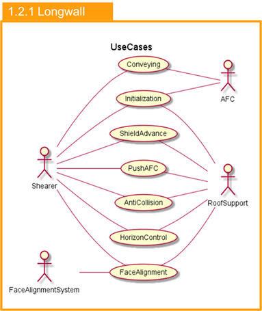
Figure 1 – Use Case Diagram for the Application Case Longwall Operation
The Initialization UC is utilized for the initial exchange of system dimensions or non-mutable data between the communication partners. It is mandatory and needs to be run every time the connection to one of the partners is (re-)established. Figure 2 shows the sequence diagram of the Initialization use case.
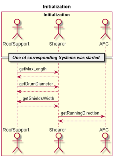
Figure 2 – Sequence diagram of the Initialization Use Case
The Shield Advance UC describes the process of moving shields towards the coal face depending on the Shearer’s position.
The Roof Support System cyclically reads the position and the running direction of the Shearer. By taking the Shearer’s position and dimensions and the actual position of the shields into account, the Roof Support System calculates which shields shall be pulled. The Roof Support System advances the corresponding shields, if necessary. This state is reflected by setting the ShieldadvanceStatus-Variable to ONGOING. Once the shield advance action is finished, i.e. all shields are in the desired position, ShieldadvanceStatus is set to FINISHED.
If necessary and applicable, the Shearer can use the Roof Support System’s ShieldadvanceStatus in its automation states.
For advanced operation, the Shearer’s drum heights can be used by the Roof Support System to determine the desired shield positions, if shield advance above the machine body is allowed. Figure 3 contains the sequence diagram of this UC.
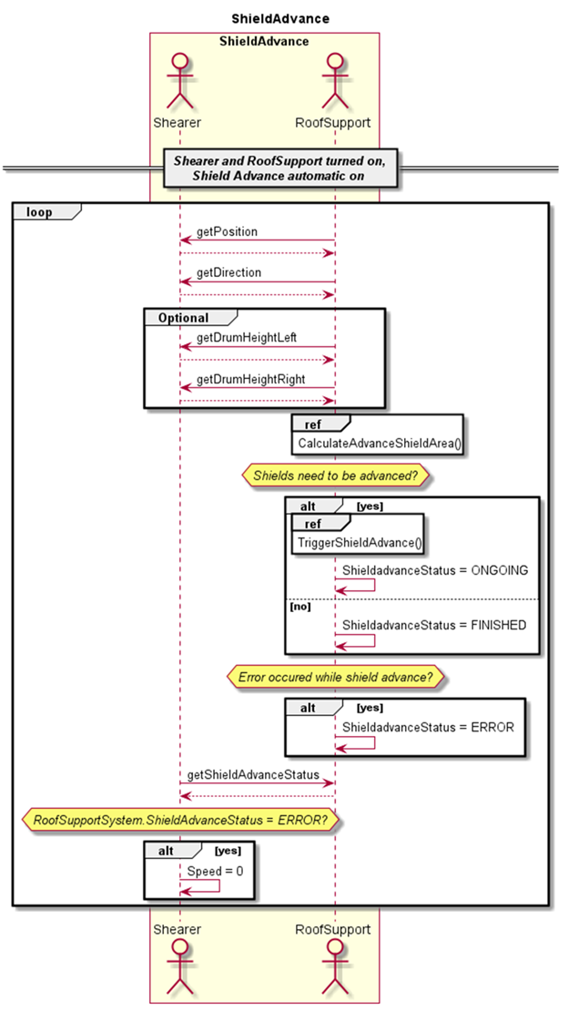
Figure 3 – Sequence diagram of the Shield Advance Use Case
This Push AFC UC describes the process of pushing the AFC towards the coal face depending on the Shearer’s position.
The Roof Support System cyclically reads the position and the running direction of the Shearer. By taking the Shearer’s position and dimensions and the actual position of the AFC sections into account, the Roof Support System calculates which sections shall be pushed. The Roof Support System advances the corresponding sections, if necessary. This state is reflected by setting the AFCPushStatus to ONGOING. If the AFC has successfully advanced all sections (i.e. all sections are in the desired position), the AFCPushStatus is set to FINISHED. The Shearer can use the AFC’s AFCPushStatus in its automation states if necessary. Figure 4 illustrates the sequence diagram of this UC.
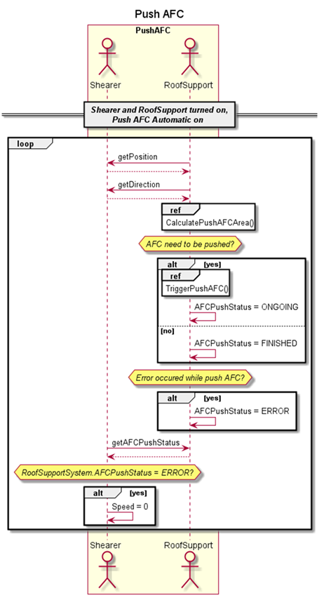
Figure 4 – Sequence diagram of the Push AFC Use Case
The Conveying UC describes the automatic adaption of the Shearer’s speed depending on the AFC’s load.
The Shearer cyclically reads the State of the AFC. If the AFC’s State is RUNNING, the Shearer reads the Load-Variable from the AFC. If the AFC’s Load exceeds a parameterizable threshold, the Shearer’s speed is limited to a certain value. For advanced operation, the AFC’s Load can be used for a linear increase of the Shearer’s maximum speed. Figure 5 displays the sequence diagram of this UC.
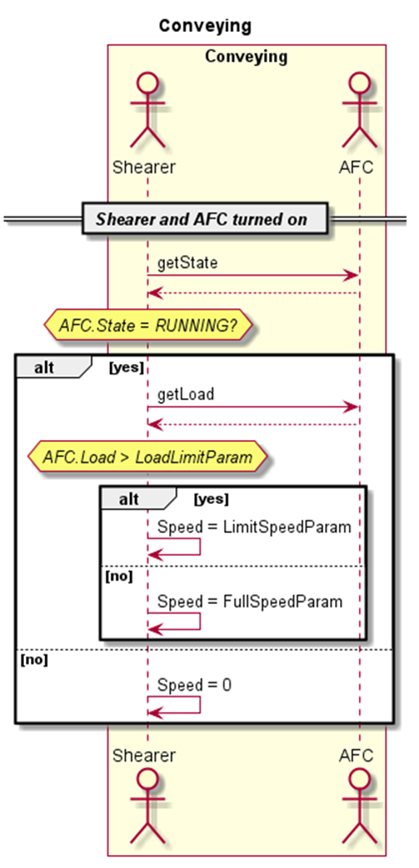
Figure 5 – Sequence diagram of the Conveying Use Case
The Anti-Collision UC describes the automated process of preventing collisions between the Shearer cutting drums and the Roof Support Shields. The Shearer receives information about the clear area and is responsible for decreasing speed or stopping before a collision would occur.
The Roof Support System cyclically reads the Shearer’s position. By taking the Shearer’s position, dimensions and the actual position of the shields into account, the Roof Support System calculates clearance values for each side of the machine (ClearanceLeft and ClearanceRight). These values reflect the area, in which it is safe for the shearer to move. The values are based on the Shearer’s center of machine.
Depending on the current project/mine, the clearance values will be determined in different ways and will include different factors. Depending on the application, the Roof Support System can check sensor values of flipper, forepole canopy, setting pressure and advance ram.
The Shearer cyclically reads the clearance value for the current movement direction (ClearanceLeft or ClearanceRight) and reduces its maximum speed, if the clearance is below a warning threshold, or even stops, if it is lower than a halt threshold.
For advanced operation, the Roof Support System’s clearance can be used for a linear increase of the Shearer’s maximum speed. Figure 6 displays the sequence diagram of this UC.
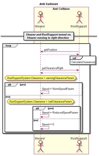
Figure 6 – Sequence diagram of the Anti-Collision Use Case
The Face Alignment UC describes the automated process for straightening the conveyor line respective to an aerial view.
The Face Alignment System cyclically reads the Shearer’s position for determining the completion of a full shear. If a full shear was detected, the Face Alignment System uses its measurements to calculate offset values for each shield. After the calculation is finished, the Face Alignment System increases its SequenceNumber.
The Roof Support System cyclically reads the SequenceNumber of the Face Alignment System. If a new SequenceNumber was detected, the Roof Support System reads the new calculated offsets from the Face Alignment System and applies these offsets for the next shear. Figure 7 contains the sequence diagram of this UC.
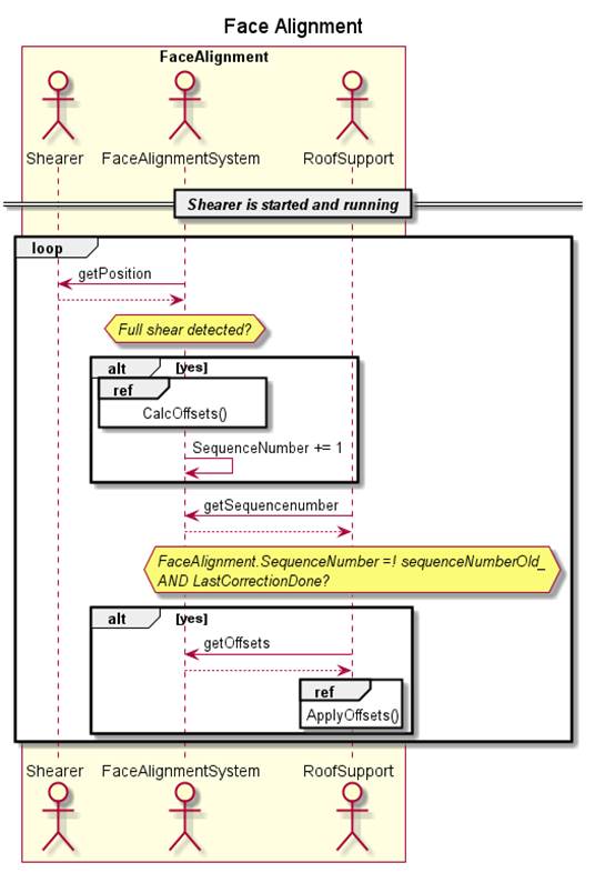
Figure 7 – Sequence diagram of the Face Alignment Use Case
The Horizon Control UC describes the process of manually correcting the cutting heights to optimize coal extraction and reduce rock cutting in specific areas. The operator uses the Roof Support System’s control panel to send correction data to the shearer.
If a new user input for either the roof or the floor offset is done, the Roof Support System sends the offset for the corresponding area (identified by StartShield and EndShield) to the Shearer.
The Shearer uses these offsets for controlling the arm heights in the next shear. Optionally, the Roof Support System can read the present FloorOffset and RoofOffset of all shields from the Shearer to allow the user to see the currently applied values. Figure 8 contains the sequence diagram of this UC.
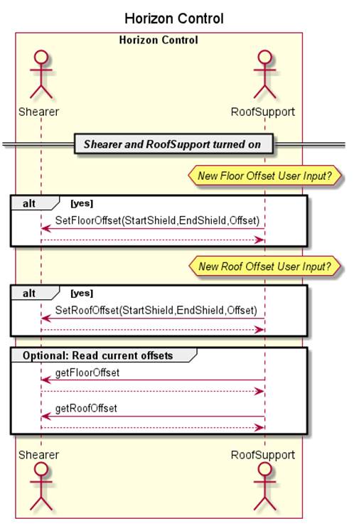
Figure 8 – Sequence diagram of the Horizon Control Use Case
___________