The SystemState is a subtype of BaseVariableType. It is used to denote a single level with one or multiple SEMI E10 states that might be active in an item. It is formally defined in Table 68.
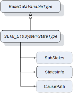
Figure 47 – SEMI_E10SystemStateType
Table 68 – SEMI_E10SystemStateType Definition
|
Attribute |
Value |
||||
|
BrowseName |
SEMI_E10SystemStateType |
||||
|
IsAbstract |
False |
||||
|
ValueRank |
-3 (-3 = ScalarOrOneDimension) |
||||
|
DataType |
SEMI_E10SystemStateDataType |
||||
|
References |
Node Class |
BrowseName |
DataType |
TypeDefinition |
Other |
|
Subtype of the 0:BaseDataVariableType defined in OPC 10000-5, i.e. inheriting the InstanceDeclarations of that Node |
|||||
|
|
|
|
|
|
|
|
0:HasComponent |
Variable |
SubStates |
SEMI_E10SystemStateDataType{ ScalarOrOneDimension} |
SEMI_E10SystemStateType |
O |
|
0:HasProperty |
Variable |
StatesInfo |
SEMI_E10SystemStateInfoDataType[] |
0:PropertyType |
M |
|
0:HasProperty |
Variable |
CausePath |
0:String |
0:PropertyType |
O |
The SubStates optional component is a recursive SEMI_E10SystemStateType to specify the next level of the sub states of the state store on the variable. It is possible to provide any number of levels to completely map all the SEMI E10 states of an item.
The StatesInfo is a mandatory property of all the states that can be assigned to the level of variable.
The CausePath optional property is a path information string based on the SEMI E10 scheme. Instantiated SEMI_E10SystemStateTypes using the SubStates component do not need to provide this property. If needed it should be instantiated only once at level one or zero of the system state.
More information about the usage of SEMI E10 in a vision system can be found in Section 11.6 of the OPC 40100-1 - UA Companion Specification Part 1 for Machine Vision.
Table 69 – SEMI E10 information for the SEMI_E10SystemStateInfoDataType
|
Id |
Name |
Parent state |
Level |
Description |
|
0 |
TotalTime |
0 |
0 |
The item total time of operation. |
|
1 |
OperationsTime |
0 |
1 |
The item is working. |
|
2 |
NonscheduledTime |
0 |
1 |
The item is not working because no production was scheduled. |
|
3 |
Uptime |
1 |
2 |
The item is in a condition to perform its intended function. |
|
4 |
Downtime |
1 |
2 |
The item is not in a condition to perform its intended function. |
|
5 |
ManufacturingTime |
3 |
3 |
The item is either working on a job or is idle and ready to accept a new job. |
|
6 |
Engineering |
3 |
3 |
The item is not working and not ready to accept a command because a user is currently working on the system |
|
7 |
ScheduledDowntime |
4 |
3 |
The item is not available for production and this was planned in advance. |
|
8 |
UnscheduledDowntime |
4 |
3 |
The item is not available for production due to failure and repair. |
|
9 |
Production |
5 |
4 |
The item is currently working on a job. |
|
10 |
Standby |
5 |
4 |
The item is ready to accept a command but is currently not executing a job. |
The different states defined in SEMI E10 can be organized in different levels depending on their position in the state hierarchy. The initial level (0) is always the TotalTime state that encapsulates the total time that the machine has been in existence, in the next level increasing the level of detail, the sub-states OperationsTime and NonscheduledTime are specified as the level 1 of the SEMI E10 states, from there OperationsTime specifies two sub-states Uptime and Downtime which become level 2 and so on. Each state has a relationship with its parent state that must be specified in the ParentStateId property of the SEMI_E10SystemStateInfoDataType with the exception of TotalTime which is the initial state and it shall refer itself as its parent state. When first instantiating a variable of the SEMI_E10SystemStateType, it shall be done starting with level 1 and then as many SEMI_E10SystemStateType variables can be instantiated as the required number of state levels, using the SubStates component. Each level must provide the corresponding information about the states on that level using the StatesInfo property. When a change of state happens on the Item it might be that a particular level must be deactivated. This is done by setting the BadStateNotActive status code on the value of the variable on the level that must be deactivated. For example, if the NonscheduledTime state becomes active all the additional sub-states below level 1 become deactivated.
Each Item (Machine or Component) can have their own individual SEMI E10 state variable. At the system level or if an Item is the master of other components the information of the SEMI E10 state of that object can take into account all the relevant information of the related Items. In addition, this companion specification defines the usage of parallel states with the usage of priority in each of the active SEMI E10 state. If parallel states are needed the value of the variable of the SEMI_E10SystemStateType will be an array and the priority value must be set in each of the elements of SEMI_E10SystemStateDataType.
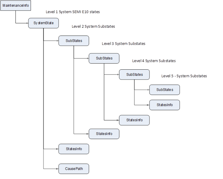
Figure 48 – SEMI E10 States and Substates example