4 Terms, abbreviated terms and conventions
It is assumed that basic concepts of OPC UA information modelling are understood in this document. This document will use these concepts to describe the MDIS Information Model.
4.1 MDIS definitions
Table 1 lists OPC UA definitions which are used in this document, they are included here as a reference. Additional information can be found in the reference documents listed in section 3.
| Term | Definition |
| AddressSpace | The collection of information that an OPC UA Server makes visible to its Clients. See OPC 10000-3 for a description of the contents and structure of the Server AddressSpace. |
| Attribute | A primitive characteristic of a Node. All Attributes are defined by OPC UA and may not be defined by Clients or Servers. Attributes are the only elements in the AddressSpace permitted to have data values. See OPC 10000-3 for additional details. |
| ConformanceUnit | As defined by the OPC Foundation: a specific set of OPC UA features that can be tested as a single entity. As it applies to MDIS a ConformanceUnit may describe a specific Object or part of a specific Object. It may also describe general functionality such as redundancy or performance. For each ConformanceUnit one or more test cases will exist to ensure that the defined functionality is provided. The test cases may be automatically executed in a Compliance Test Tool (CTT) or they may require some level of manual interaction. See OPC 10000-7 for additional details. |
| Facet | A Profile that describes a subset of functionality. This functionality must be paired with other Facets or Profiles to provide an operating Server or Client. See OPC 10000-7 for additional details. |
| InformationModel | An organisational framework that defines, characterises and relates information resources of a given system or set of systems. The core address space model supports the representation of InformationModels in the AddressSpace. See OPC 10000-5 for a description of the base OPC UA Information Model. |
| Method | A callable software function that is a component of an Object. See OPC 10000-4 for a basic definition. |
| Node | The fundamental component of an AddressSpace. See OPC 10000-3 for additional details. |
| NodeClass | The class of a Node in an AddressSpace. NodeClasses define the metadata for the components of the OPC UA Object Model. They also define constructs, such as Views, that are used to organise the AddressSpace. See OPC 10000-3 for additional details. |
| Object | Objects from an object-oriented technology point of view would have the following definition. Objects share two characteristics: They have state (Attribute) and behaviour (Method). A bicycle has states (current gear, current pedal cadence, current speed) and behaviour (changing gear, changing pedal cadence, applying brakes). An object stores its state in fields (Variables) and exposes its behaviour through functions (Methods). Functions operate on an object's internal state and serve as the primary mechanism for object-to-object communication. Hiding internal state and requiring all interaction to be performed through an object's functions is known as data encapsulation, a fundamental principle of object-oriented programming. In programming languages this object will have a third characteristic: The identity, which will help to find and use the object. From an OPC UA point of view the following definition is used: A Node that represents a physical or abstract element of a system. Objects are modelled using the OPC UA Object Model. Systems, subsystems and devices are examples of Objects. An Object is defined as an instance of an ObjectType. See OPC 10000-3 for additional details. |
| Object Instance | A synonym for Object. See OPC 10000-3 and OPC 10000-5 for additional details. |
| ObjectType | A Node that represents the TypeDefinition for an Object. See OPC 10000-3 and OPC 10000-5 for additional details. |
| Profile | A specific set of capabilities, to which a Server or Client may claim conformance. The capabilities are defined by a set of ConformanceUnits. Each Server or Client may claim conformance to more than one Profile. The OPC Foundation provides a base list of Server and Client Profiles and Facets in an online database which is also documented in an OPC UA specification, OPC 10000-7. The online database can be found here: |
| Property | A Variable that is a leaf and cannot have any children. See OPC 10000-3 and OPC 10000-5 for additional details. |
| Reference | An explicit relationship (a named pointer) from one Node to another. The Node that contains the Reference is the source Node and the referenced Node is the target Node. All References are defined by ReferenceTypes. See OPC 10000-3 and OPC 10000-5 for additional details. |
| ReferenceType | A Node that represents the TypeDefinition of a Reference. The ReferenceType specifies the semantics of a Reference. The name of a ReferenceType identifies how source Nodes are related to TargetNodes and generally reflects an operation between the two, such as "A contains B". See OPC 10000-3 and OPC 10000-5 for additional details. |
| UANodeSet | The root of the AddressSpace defined in an XML document. It defines a set of Nodes, their Attributes and References. See OPC 10000-5 for additional details. |
| Variable | Variable is a Node that contains a value and can have children. See OPC 10000-3 and OPC 10000-5 for additional details. |
| VariableType | A Node that represents the TypeDefinition for a Variable. See OPC 10000-3 and OPC 10000-5 for additional details. |
4.2 Abbreviated terms
The abbreviations, acronyms and definitions listed in Table 2 are typical and primarily focused on Subsea projects although some Topsides specific terms are also included.
| Abbreviations, Acronyms & Definitions | |
| API | American Petroleum Institute |
| CIMV | Chemical Injection Metering Valves |
| CSV | Comma Separated Values |
| DCS | Distributed Control System |
| EPU | Electrical Power Unit (Part of PCU) |
| ERP | Enterprise Resource Planning |
| EU | Engineering Units |
| FEED | Front End Engineering Design |
| HMI | Human Machine Interface |
| HTTP | Hypertext Transfer Protocol |
| IEC | International Electrotechnical Commission |
| JIP | Joint Industry Project |
| LVDT | Linear Variable Displacement (Differential) Transmitter |
| MCS | Master Control Station (Subsea Process Control System) |
| MDIS | MCS-DCS Interface Standardisation (Industry JIP) |
| MPFM | Multiphase Flow Meters |
| NTP | Network Time Protocol |
| OLE | Object Linking & Embedding |
| OPC | Open Process Control (original Classic was OLE for Process Control) |
| OPC UA | OPC Unified Architecture |
| ROV | Remotely Operated Vehicle |
| SCADA | Supervisory Control And Data Acquisition |
| SCV | Subsea Controls Vendor |
| SEM | Subsea Electronics Module |
| SIS | Safety Instrumented System |
| SPCS | Subsea Production Control System |
| TCP/IP | Transmission Control Protocol / Internet Protocol |
| UML | Unified Modelling Language |
| URL | Uniform Resource Locator |
| XML | Extensible Mark-up Language |
The OPC UA Specifications are also available from the IEC as IEC 62541
4.3 OPC UA Overview
4.3.1 Introduction
For the MDIS user who may not be familiar with OPC UA, the following section provides a brief overview of key features. It does not describe how MDIS makes use of these features it only describes the features available in OPC UA. MDIS specific functionality is specified in other sections of this document.
4.3.2 What is OPC UA?
OPC UA is an open and royalty free standard designed as a universal communications protocol. It is also available as IEC 62541.
OPC UA has a broad scope which delivers economies of scale for application developers. When combined with powerful semantic models, OPC UA makes it easier for end users to access data via generic commercial application. It provides an information modelling framework that allows application developers to represent their data in a way that makes sense to them.
The OPC UA model is scalable from small devices to Enterprise Resource Planning (ERP) systems. OPC UA devices process information locally and then provides that data in a consistent format to any application requesting data. For a more complete overview see OPC 10000-1.
4.3.3 Basics of OPC UA
As an Open Standard, OPC UA is based on standard Internet technologies, such as TCP/IP, HTTP, Ethernet and XML. OPC UA provides a set of services (see OPC 10000-4) and a basic information model framework.
As an Extensible Standard, OPC UA provides an information model framework which can expose vendor defined information in a standard way. More importantly all OPC UA Clients are expected to be able to discover and use vendor defined information. This means OPC UA users can benefit from the economies of scale that come with generic visualisation and interface applications. This specification is an example of an OPC UA InformationModel designed to meet the needs of developers and users in the offshore oil and gas industry.
OPC UA Clients can be any consumer of data, from devices / controllers on the network; browser based thin clients and higher level ERP systems. OPC UA applications are platform and development language dependant. The full scope of OPC UA applications are illustrated in Figure 1. For this companion specification the typical communication would be device to device or device to SCADA type communications.

OPC UA provides a robust and reliable communication infrastructure having mechanisms for handling lost messages, recovering from network interruptions, etc. With its binary encoded data it offers a high-performance data exchange solution. Security is built into OPC UA, security requirements are becoming more and more important as, increasingly, environments are connected to the office network or the internet and attackers are starting to focus on automation systems
4.3.4 Information Modelling in OPC UA
4.3.4.1 Concepts
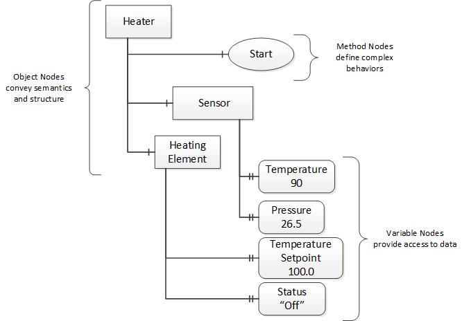
OPC UA provides a framework that can be used to represent complex information as Objects in an AddressSpace which can be accessed with standard web services. These consist of Nodes connected by References. Different classes of Nodes convey different semantics. For example, a Variable Node represents a value that can be read or written. The Variable Node has an associated DataType that can define the actual value, such as a string, float, structure etc. It can also describe the Variable value as a variant. A Method Node represents a function that can be called. Every Node has a number of Attributes including a unique identifier called a NodeId and non-localised name called a BrowseName. An Object representing a Heater is shown in Figure 2.
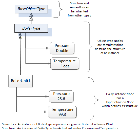
Object and Variable Nodes are called Instance Nodes and they always reference a TypeDefinition (ObjectType or VariableType) Node which describes their semantics and structure. Figure 3 illustrates the relationship between an instance and its TypeDefinition.
Type Nodes are templates that define all of the children that can be present in an instance of the type. In the example in Figure 3 the BoilerType ObjectType defines two sensors: Pressure and Temperature. All instances of BoilerType are expected to have the same children with the same BrowseNames. Within a type the BrowseNames uniquely identify the child. This means Client applications can be designed to search for children based on the BrowseNames from the type instead of NodeIds. This eliminates the need for manual reconfiguration of systems if a Client uses types that multiple devices implement.
OPC UA also supports the concept of subtyping. This allows a modeller to take an existing type and extend it. There are rules regarding subtyping defined in OPC 10000-3, but in general they allow the extension of a given type or the restriction of a DataType. For example, the modeller may decide that the existing ObjectType in some cases needs an additional Variable. The modeller can create a subtype of the Object and add the Variable. A Client that is expecting the parent type can treat the new type as if it was of the parent type. With regard to DataTypes, if a Variable is defined to have a numeric value, a subtype could restrict the value to a float. This standard adds additional rules for extensions.
References allow Nodes to be connected together in ways that describe their relationships. All References have a ReferenceType that specifies the semantics of the relationship. References can be hierarchical or non-hierarchical. Hierarchical References are used to create the structure of Objects and Variables. Non-hierarchical References are used to create arbitrary associations. Applications can define their own ReferenceType by creating subtypes of the existing ReferenceType. Subtypes inherit the semantics of the parent but may add additional restrictions. Figure 4 depicts several References connecting different Objects.

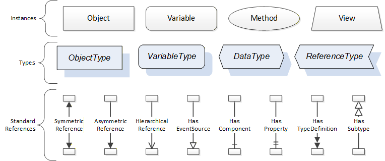
The figures above use a notation that was developed for the OPC UA specification. The notation is summarised in Figure 5. UML representations can also be used; however, the OPC UA notation is less ambiguous because there is a direct mapping from the elements in the figures to Nodes in the AddressSpace of an OPC UA Server.
A complete description of the different types of Nodes and References can be found in OPC 10000-3 and the base OPC UA AddressSpace is described in OPC 10000-5.
The OPC UA specification defines a very wide range of functionality in its basic information model. It is not expected that all Clients or Servers support all functionality in the OPC UA specifications. OPC UA includes the concept of Profiles, which segment the functionality into testable certifiable units. This allows the development of companion specifications (such as OPC UA MDIS) that can describe the subset of functionality that is expected to be implemented. The Profiles do not restrict functionality but generate requirements for a minimum set of functionality (see OPC 10000-7).
The OPC Foundation also defines a set of InformationModels that provide a basic set of functionalities. The Data Access specification (see OPC 10000-8) provides a basic InformationModel for typical process or measured data. The Alarm and Condition specification (see OPC 10000-9) defines a standard InformationModel for Alarms and Conditions. The Programs specification (see OPC 10000-10) defines a standard InformationModel for extending the functionality available via Method calls and state machines. The Historical Access specification (see OPC 10000-11) defines the InformationModel associated with Historical Data and Historical Events. The aggregates specification (see OPC 10000-13) defines a series of standard aggregate functions that allow a Client to request summary data. Examples of aggregates include averages, minimums, time in state, standard deviation, etc.
4.3.4.2 Namespaces
OPC UA allows information from many different sources to be combined into a single coherent AddressSpace. Namespaces are used to make this possible by eliminating naming and id conflicts between information from different sources. Namespaces in OPC UA have a globally unique string called a NamespaceUri and a locally unique integer called a NamespaceIndex. The NamespaceIndex is only unique within the context of a Session between an OPC UA Client and an OPC UA Server. All of the web services defined for OPC UA use the NamespaceIndex to specify the Namespace for qualified values.
There are two types of values in OPC UA that are qualified with Namespaces: NodeIds and QualifiedNames. NodeIds are globally unique identifiers for Nodes. This means the same Node with the same NodeId can appear in many Servers. This, in turn, means Clients can have built in knowledge of some Nodes. OPC UA InformationModels generally define globally unique NodeIds for the TypeDefinitions defined by the InformationModel.
QualifiedNames are non-localised names qualified with a Namespace. They are used for the BrowseNames of Nodes and allow the same names to be used by different InformationModels without conflict. The BrowseName is used to identify the children within a TypeDefinition. Instances of a TypeDefinition are expected to have children with the same BrowseNames. TypeDefinitions are not allowed to have children with duplicate BrowseNames; however, instances do not have that restriction.
4.3.4.3 Companion Specifications
An OPC UA companion specification for an industry specific vertical market describes an InformationModel by defining ObjectTypes, VariableTypes, DataTypes and ReferenceTypes that represent the concepts used in the vertical market. Table 3 contains an example of an ObjectType definition.
| Attribute | Value | |||||
| BrowseName | BoilerType | |||||
| IsAbstract | False | |||||
| Reference | NodeClass | BrowseName | DataType | TypeDefinition | ModellingRule | |
|---|---|---|---|---|---|---|
| Subtype of the BaseObjectType from OPC 10000-3. | ||||||
| 0:HasProperty | Variable | Pressure | Double | 0:PropertyType | Mandatory | |
| 0:HasProperty | Variable | Temperature | Float | 0:PropertyType | Mandatory | |
| 0:HasProperty | Variable | Flow | Double | 0:PropertyType | Optional | |
The BrowseName is a non-localised name for an ObjectType.
IsAbstract is a flag indicating whether instances of the ObjectType can be created. If IsAbstract is FALSE then instances of this ObjectType may be created. If IsAbstract is TRUE then instances of the ObjectType cannot be created, the ObjectType must be subtyped.
The bottom of the table lists the child Nodes for the type. The Reference column is the type of Reference between the Object instance and the child Node. The NodeClass is the class of Node. The BrowseName is the non-localised name for the child. The DataType is the structure of the Value accessible via the Node (only used for Variable NodeClass Nodes) and the TypeDefinition is the ObjectType or VariableType for the child.
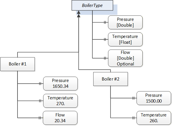
The ModellingRule indicates whether a child is Mandatory or Optional. It can also indicate cardinality. Note that the BrowseName is not defined if the cardinality is greater than 1. visually depicts the ObjectType defined in Table 3 along with two instances of the ObjectType. The first instance includes the Optional Property while the second does not.