IO-Link is the first standardized IO technology worldwide (IEC 61131-9) for the communication with sensors and actuators. The powerful point-to-point communication is based on the long established 3-wire sensor and actuator connection without additional requirements regarding the cable material. So, IO-Link is no fieldbus but the further development of the existing, tried-and-tested connection technology for sensors and actuators.
An IO-Link system consists of an IO-Link Master, IO-Link Devices and the cables that connect the IO-Link Devices to the IO-Link Master’s ports. The IO-Link Master establishes the connection between the IO-Link Devices and the automation system and maintains point-to-point connections to the IO-Link Devices. Figure 1 gives an example of a system architecture with IO-Link.
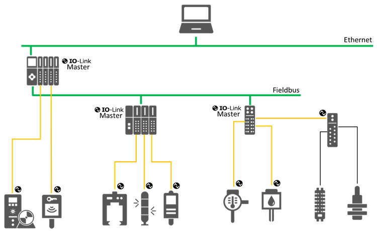
Figure 1 – System Architecture with IO-Link (Example)
Figure 1 uses the following colour code: Green for Ethernet and Fieldbus connections, orange for IO-Link connections and black for non-IO-Link sensor/actuator connections. Note that IOLink Masters can be implemented at different levels of the hierarchy and be combined with different kinds of devices such as fieldbus masters, gateways, etc.
Each IO-Link Device has an IODD (IO Device Description). This is a device description file which contains information about the manufacturer, article number, functionality etc. This information can be easily read and processed by the user. Each device can be unambiguously identified via the IODD as well as via an internal device ID.