This enumeration specifies the different options in placing the machine processing coordinate systems. The eight different options are shown in Figure 16, as well as some examples in Figure 17 and Figure 18.
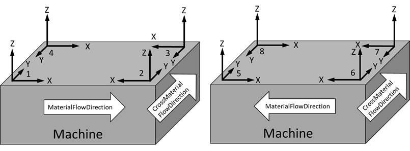
Figure 16 – Machine processing coordinate systems
The enumeration is defined in Table 79.
Table 79 – CoordinateSystemEnumeration Items
|
Name |
Value |
Description |
|
Unknown |
0 |
The CoordinateSystem is unknown. |
|
System1 |
1 |
Lefthanded system, X-axis along material flow, Y-axis along cross material flow |
|
System2 |
2 |
Righthanded system, X-axis against material flow, Y-axis along cross material flow |
|
System3 |
3 |
Lefthanded system, X-axis against material flow, Y-axis against cross material flow |
|
System4 |
4 |
Righthanded system, X-axis along material flow, Y-axis against cross material flow |
|
System5 |
5 |
Lefthanded system, X-axis against material flow, Y-axis along cross material flow |
|
System6 |
6 |
Righthanded system, X-axis along material flow, Y-axis along cross material flow |
|
System7 |
7 |
Lefthanded system, X-axis along material flow, Y-axis against cross material flow |
|
System8 |
8 |
Righthanded system, X-axis against material flow, Y-axis against cross material flow |
Its representation in the AddressSpace is defined in Table 80.
Table 80 – CoordinateSystemEnumeration Definition
|
Attribute |
Value |
|||||
|
BrowseName |
CoordinateSystemEnumeration |
|||||
|
IsAbstract |
False |
|||||
|
References |
NodeClass |
BrowseName |
DataType |
TypeDefinition |
Other |
|
|
Subtype of the Enumeration type defined in OPC 10000-5 |
||||||
|
0:HasProperty |
Variable |
0:EnumStrings |
0:LocalizedText[] |
0:PropertyType |
|
|
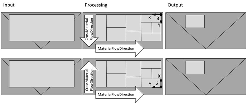
Figure 17 – Example of glass processing machines for flat lying processing (top view)
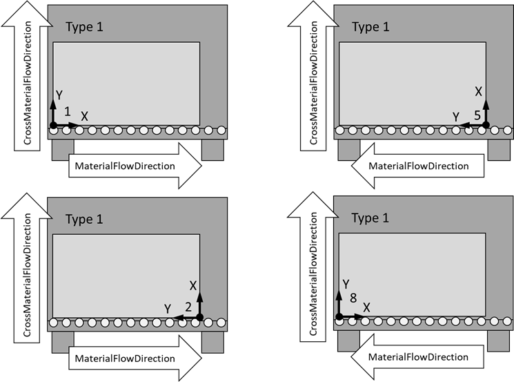
Figure 18 – Example of glass processing machines with standing processing (front view)